1
Operator Manual
Digital Communication
and
Measurement Receiver / Transceiver
RDR54 / 50
Version:
English V 4.07
First posted: 31.10.2012
Last change: 18.11.2013
Konstruktion & Musterbau
Burkhard Reuter
Ziegelstrasse 54
www.Reuter-Elektronik.de
06862 Dessau-Rosslau
Germany
Content
1. Overview
Page 6
2. Specifications
Page 7
3. Safety precautions
Page 9
4. Device description
Page 10
4.1 Mechanics
Page 10
4.2 Electronics
Page 10
4.3 Firmware
Page 11
5. Operation
Page 12
5.1 Controls and connectors
Page 12
5.2 Receiving frequency
Page 15
5.3 Tuning
Page 15
Special function of the key "0"
Page 16
5.4 Bandwidth
Page 17
5.5 Demodulators
Page 19
5.6 Notchfilter
Page 21
5.7 Level scaling and gain adjustment
Page 22
5.8 Noise reduction DNR
Page 23
5.9 Noise blanker NB
Page 24
5.10 Videofilter
Page 25
5.11 Surround sound
Page 25
5.12 S-Meter
Page 26
6. Dialogues
Page 27
6.1 Setup dialog
Page 27
Handwheel Automatic
Page 28
Deadtime Handwheel Switch (ms)
Page 29
Display Diagram
Page 29
VERSION
DATUM
NAME
English 1.1
13/11/13
B.Reuter / R.Menn
K & M Burkhard Reuter
RDR54_BA_V300.PDF
Page
2
Contents (continued)
Loudspeaker
Page 33
Display Brightness
Page 33
Level Units
Page 34
Vertical and horizontal grid lines
Page 34
RF Gain Control
Page 34
Holdtime (s)
Page 34
Attackrate (dB / s)
Page 34
ANT1 Highpass (kHz)
Page 34
Preamplifier 0-54 MHz (db)
Page 34
Attenuator 0-30 MHz (dB)
Page 34
Impedance 0-30 MHz (ohms)
Page 34
Filter Highpass / Lowpass
Page 34
Audio Highpass
Page 35
6.2 Memory dialog
Page 36
Calibration Oscillator
Page 36
Level (dB)
Page 36
Undo back to level
Page 36
Setting save to No.
Page 37
Setting load from No.
Page 37
AF-Level (%)
Page 37
FM Dev (kHz)
Page 37
Freq L
Page 37
Freq R
Page 37
7. Special features
Page 38
7.1 Undo Function
Page 38
7.2 Defaults
Page 39
7.3 Software Update
Page 39
Bootloader
Page 39
Software Download
Page 40
VERSION
DATE
NAME
English 1.1
13/11/13
B. Reuter / R. Menn
K
RDR54 BA_V300.PDF
Page
3
7.4 Data Upload / Copy Display
Page 42
7.5 Test Generator
Page 43
8. First steps
Page 48
8.1 Unpacking and first-time operation
Page 48
8.2 Getting Started
Page 48
Setting DCF77
Page 49
8.3 Common settings for radio reception
Page 50
AM radio reception
Page 50
SSB reception
Page 51
CW reception
Page 51
9. Troubleshooting
Page 53
I don’t see anything (on the spectrum display)!
Page 53
I can’t hear anything!
Page 53
This button does not what I want!
Page 53
Closing a dialogue RDR54 falls into an unexpected state!
Page 53
I cannot change this value!
Page 54
The frequency cannot be shifted!
Page 54
The notch filter cannot be shifted!
Page 54
A marker cannot be moved!
Page 54
10. FM module RFM32
Page 55
10.1 Hardware
Page 55
10.2 Software
Page 55
10.3 Technical data RFM32
Page 56
11. Transmitter module RPA5
Page 57
11.1 Overview
Page 57
11.2 Technical data
Page 59
VERSION
DATUM
NAME
English 1.1
13/11/13
B.Reuter / R.Menn
K & M Burkhard Reuter
RDR54_BA_V300.PDF
Page
4
11.3 Operation
Page 60
11.4 Using the test generator
Page 67
Mode "SBCW"
Page 67
11.5 Connection of microphone, PTT and CW key to the transmitter module
Page 68
11.6 Additional Information
Page 71
12. Installation instructions for modules
Page 72
13. Current extensions
Page 75
13.1 Software version 301
Page 75
13.2 Replacement / Expansion Modules
Pege 78
14. RDR50A
Page 83
14.1 Differences to the RDR54
Page 83
14.2 Operation
Page 84
14.3 Firmware update
Page 86
14.4 Revision B
Page 88
14.5 Software enhancements
Page 90
VERSION
DATE
NAME
English 1.1
13/11/13
B. Reuter / R. Menn
K
RDR54 BA_V300.PDF
Page
5
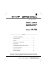
1. Overview
The RDR54 receiver covers a frequency range from 1 kHz to 30 MHz, with signal processing of AM and FM
signals detecting frequencies down to 0 Hz. An option is available to cover 50 - 54 MHz, 87.5 - 108 MHz and
144-148 MHz.
The received and demodulated signals from two independent audio channels are available via a stereo headset
and / or the built-in speaker (function “communications receiver”). Signals with double sideband modulation,
single sideband, with or without a carrier, keyed signals (CW, Morse radio) as well as FM signals can be
received. The receiver bandwidth is adjustable within a wide range, either with a manual gain or via the
configurable automatic gain control.
The RDR54 receiver is based on digital signal processing representing an enhanced Software Defined Radio
(SDR) approach. The digitization of the received signal is performed without prior frequency conversion directly
to the digital domain using a total bandwidth of about 150 MHz. A second conversion is done from the time
domain into the frequency domain using fast proprietary algorithms (no FFT). The result is a spectrum of
approximately 164 kHz width, "cut out" with a selectable frequency resolution. Additional signal processing is
performed then in the frequency domain, except for FM.
The received signals are represented as a spectrum with high resolution and accuracy in an amplitudefrequency diagram (function “measurements receiver”). The resolution can be set manually as low as 2.5 Hz per
column (roughly corresponding to the parameter "Residual Bandwidth RBW" in conventional spectrum
analyzers). A dynamic range of approximately 140 dB between the noise floor of the unit and the maximum
input voltage can be achieved. The spectrum can also be shown as a "waterfall diagram" with selectable speed.
The unit is equipped with its own power supply and is designed as a tabletop unit for indoor use. Size and
weight allow easy portability. A USB 2.0 interface is provided for remote device control and data acquisition
The receiver architecture consists of a base mainframe unit with plug-in modules which are easily replaceable.
All major software components are upgradeable via the USB interface, as well as all the hardware
configurations used in the programmable circuits (FPGA). Connection to an Ethernet network is possible using
an optional module.
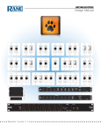
RDR54 Main display window
VERSION
DATUM
NAME
English 1.1
13/11/13
B.Reuter / R.Menn
K & M Burkhard Reuter
RDR54_BA_V300.PDF
Page
6
2. Specifications
Frequency range (antenna input):
1 kHz to 30 MHz
Optional 50 to 54 MHz, 87.5 to 108 MHz, 144 to 148 MHz
Tuning:
step increment 0.5 Hz to 999,999.5 Hz, direct input from the
keyboard for almost all values
Frequency deviation (internal oscillator):
<± 1 ppm min after 10 min., internal manual calibration
External synchronization:
about ± 100 ppm at 0 dBm external oscillator level
Input impedance:
50 ohms, 22 µF blocking capacitor internal / 25 V-
Max. input level:
0 dBm, +20 dBm with attenuator (not for 6m)
Preamplifier (switchable):
Inverting type with 1k ohms feedback resistance and 0 ohm
input resistance (idealized)
Level of accuracy:
<± 1 dB without filter, <+1 -2 dB with automatic RF-Filter
Low-pass filter (1 dB limit):
AUTOmatically tuned, MANUally selectable, 50M, 87M and
144M or OFF
High-pass filter (1 dB limit):
AUTOmatically tuned, MANUally selectable, 54M, 108M, 148M
or OFF
Gain control range (manual and automatic):
140 dB in 0.5 dB steps
Hold time control:
0 ... 99.5 s in 0.5 s steps
AGC speed control:
0.1 ... 99.5 dB/s in 0.1 … 0.5 dB/s increments
Dynamic range ADC:
17 bit, at least 105 dB, intermodulation and aliasing dependent
Dynamic range of signal processing:
at least 36 bit linear, audio and dB-converted signals 18-32 bit
Resolution time-frequency conversion:
2.5 Hz ... 320 Hz in 8 steps (each doubling)
Frequency band time-frequency conversion:
Receive channels:
163.84 kHz, 4-times over sampling
2 channel audio, 1 video channel (spectrum for measurement
purposes and waterfall diagram), independently adjustable
frequency bands within the t / f conversion range
Demodulation audio channels:
SYNC (A3E, H3E carrier synchronous), DSB (A3E, H3E
without carrier), LSB and USB (J3E), CW (A1A), narrow-band
FM max. ± 5 kHz deviation, wide-band FM (see module
RFM32), AM-E (AM envelope detector)
Demodulator bandwidth (= audio bandwidth):
2.5 Hz ... 20.0 kHz (5 Hz steps minimum), fixed at 5, 7, 10 or
14 kHz for FM-N and AM-E
DNR Noise reduction system:
2 algorithms: IQ process: Stage 1 - 9 (19), magnitude method:
Level 10 (20) - 19 (39). Values in brackets for double-sideband
demodulators.
NB Noise Blanker:
Adjustable response threshold (16 levels) and blanking time (0
- 99 ms)
VERSION
DATE
NAME
English 1.1
13/11/13
B. Reuter / R. Menn
K
RDR54 BA_V300.PDF
Page
7
Speaker channel:
PWM ("Class D"), 10 Vpp level Ri = 0.2 ohms, 13 - 18 bit
resolution, internal filter, maximum power 2 W
Headphone channels:
2 independent, stereo, 24-bit DAC, max. 13 mW at 16 ohms
Spectral resolution x-axis (frequency):
640 columns / 20 scale units, resolution of 2.5 Hz ... 320 Hz /
col in 8 steps (each doubling)
Spectral resolution y-axis (level):
320 lines / 8 scale units, 0.05 ... 0.5 dB / line (2 ... 20 dB / scale
unit) in 4 steps, dBµV or dBm scale, 2 markers, S-level display
with 0.1 S resolution, y-position adjustable max. 240 dB
Video spectral filters:
Off, arithmetic average, quasi-peak, maximum hold at 0 ... 9.9
s or infinite measurement time (automatic reset to 0 at the end
of the manually set measurement time)
Frame rate (spectra / s):
4 times the frequency resolution, max. 57.14 frames per
second
Waterfall speed:
8.75 / 17.5 / 35 ms / line (0.35 / 0.7 / 1.4 s / scale unit)
Color levels for level scaling waterfall:
16 (2 colors per scale unit of y-axis of the spectrum)
Memories:
63 for Undo, 63 free programmable, memory position “0”
reserved for the factory setting / bootloader
Display (WVGA):
TFT 5.0 inch (12.7 cm) diagonal, 800 x 480 pixels, 256 colors,
max brightness 350 cd / m², viewing angle (horizontal /
vertical) 90 ° / 70 °, contrast (black / white) 250, reaction time
35 ms
SMB connectors (male):
ANT1 (1 kHz ... 30 MHz), ANT2 (50 ... 54 MHz), IN1 (0.1 kHz...
150 MHz -3 dB without aliasing filter), CLK (external oscillator
83.88608 MHz with 0 dBm)
Other connections:
3.5 mm stereo headphone jack,
3.5 mm jack S / PDIF (digital audio, only special versions),
Mini-USB 2.0 Type B, high-speed 480 Mbps
Power supply:
110 / 230 V Class I, <25 VA, <1 VA standby
Size (width / height / depth):
290 mm / 125 mm (folded up feet) / 245 mm
Weight:
max. about 5 kg, depending on the version / equipment
Environmental conditions:
0 ... +50 ° C or 32 ... 125F ambient temperature <= 90% rel.
humidity non-condensing, indoor use pollution class 2
Compliance:
CE according to DIN EN 55013, EN 55020, EN 60065
(Consumer electronics and related equipment),
RoHS / WEEE Directive, ear-Reg. 27676700
VERSION
DATUM
NAME
English 1.1
13/11/13
B.Reuter / R.Menn
K & M Burkhard Reuter
RDR54_BA_V300.PDF
Page
8
3. Safety precautions
Please always note the following safety precautions!
The device is intended for use at 110 V or 230 V AC mains voltage. Make the connection using the
provided or an equivalent AC cable with ground pin to a properly grounded socket! Damaged cables
must be replaced immediately, damaged sockets should not be used!
Carefully check the voltages of the power supply! Connect the equipment into an outlet only with fuse
protection of 16 amps or less! Voltage, frequency and power consumption of the device are labelled on
the back near the power connector.
Disconnect (pull plug) electric power, in case you want to remove screws or would like to open the
receiver! The unit contains no user-serviceable components for replacement (eg. bulbs or fuses).
The device is intended for indoor use. Avoid excessive moisture, never put liquid filled containers on
top of the unit! If you accidentally put moisture (such as spilled beverages) into the device, pull the
power plug from the socket immediately and send the unit back to check on the supplier!
Check the recommended temperature range before using the equipment! Don’t switch the unit “on”
when temperature is above or below the recommended range! The device has a fan on the back near
the power connector for dissipating heat. Do never obstruct the fan opening (for example, by using the
device on towels or newspapers) and set it always so that there are at least 10 cm (4 inches) between
the rear panel and other items! Do not place open flames such as candles right next to the device!
Always provide a safe placement on a flat, straight and solid base of sufficient carrying capacity!
Transport the device only in either solid boxes or crates (for example the shipping container), or
transport it by firmly grasping the sides with both hands! The unit can cause an injury in case of a drop
under its own weight!
Do not expose this equipment to mechanical stress caused by impact, pressure, vibration or shock
which exceed that commonly used in the home with the use of electronic devices! The control elements
and specifically the front window of the display are very sensitive to pressure or impact. Never press a
control with a force beyond the extent necessary and do not press on the display (except display with
touch screen)!
If you notice any damage to the device, disconnect it (pull the AC plug) and stop the operation
immediately! Send it in for repair to the supplier if necessary.
Would you like to dispose the device due to damage or no more usability, send it back to the supplier or
return it to your local waste collection center. Dispose of the appliance elsewhere, such as households,
pollutes our environment!
Use for cleaning of the equipment only soft, lint-free and dry cloth! Be especially carefully in cleaning
the front screen of the display, because this is easily scratched. Do not use aggressive solvents, but at
most a slight moistening swab with distilled water or a damp piece of cloth or microfiber! Make sure
that no moisture goes into the device!
VERSION
DATE
NAME
English 1.1
13/11/13
B. Reuter / R. Menn
K
RDR54 BA_V300.PDF
Page
9
4. Device description
4.1 Mechanics
The RDR54 consists of a system enclosure and discrete modules. The RDR54 uses a main frame masterboard
with slots for the function modules. All components are electrically connected through the backplane.
The enclosure itself is made of two machined aluminium side walls and a bottom and lid made of extruded
aluminium. These four parts are held together by a total of 16 M3 Torx-head screws. The backplane is inserted
into corresponding slots milled out of the side walls and receptacles in the floor / cover profile.
The modules (also called plug-in cards) are inserted either from the front or the rear of the enclosure. The
RDR54 uses modules in two different lengths: short modules for the front panel and longer ones for the rear
back panel. The modules’ connectors are inserted into corresponding sockets of the backplane. They are
secured by screwing them into the base plate of the housing. For that purpose the bottom plate has inserted
threaded hole strips on front and rear. The modules are not screwed to the lid , but simply inserted into a
corresponding groove of the top.
After loosing the side screws the top plate may be lifted so that access to the modules is possible: Modules can
be removed after loosening the bottom plate screws.
The RDR54 contains no user serviceable parts. Changing modules is not planned as such. The device contains
a self-resetting fuse which in case of an eventual failure must not be exchanged by the user.
The built-in RDR54 modules are described in the section "Operation". Unused slots are covered with a blank
plate. The rear panel shows the vendor and device labels, please do not remove the labels.
4.2 Electronics
The modules are interconnected by the serial bus system. Here, the data exchange takes place under the
direction of a proprietary operating system (RMF22). It recognizes the existing modules and organizes the data
exchange in such a way that each module can communicate correctly, no matter to which slot on the backplane
it is plugged in. The operating system provides the functionality of the modules on a higher command level to all
other modules (eg. keyboard functionality or graphic commands). The RDR25 module (or software task
installed on the module) is responsible for the basic functionality of the equipment (as “master”). In the RDR54
this is the signal processing card RDR25 from firmware version “C” on.
Three bus systems connect the modules to handle the data exchange:
- JTAG bus for test purposes and for the basic programming of the device (only at the manufacturer)
- LVDS bus for distribution of the ADC data to all slots
- UART bus for exchange of operating system commands.
The LVDS bus system is used (in addition to the signal-generating ADC module RAD17) in the RDR54 only by
the signal processing board RDR25.
There is a special connection between the signal processing board RDR25 to the graphics card FGC1 and the
speaker module FDA20. Through this connection (LVDS level, proprietary protocol), high-speed data is
transferred (about 84 MBit / s), which enables a high frame rate on the screen and a high possible audio
frequency for the output signal.
VERSION
DATUM
NAME
English 1.1
13/11/13
B.Reuter / R.Menn
K & M Burkhard Reuter
RDR54_BA_V300.PDF
Page
10
4.3 Firmware
With the exception of the signal processing board RDR25, all modules are running standard software which
provides the functionality of the plug-in modules as slave units. These modules have nothing to do with the
basic device functionality, they only carry out commands or generate / process the same data sets (eg. graphics
commands for the generation of characters for text or graphics on the display). The modules can provide their
functionality for various types of equipment and utilities, for example in a measuring application as an
oscilloscope or signal generator.
The actual device function as well as the entire user interface is provided by the software of the signal
processing board RDR25. It also processes the data from the ADC module RAD17, the processed data is then
sent to the video card FGC1 and audio card FDA20.
To perform these functions on the card, a highly integrated FPGA (field programmable gate array) is provided
which is programmed as a SOC "system on a chip". Here all the necessary components are modelled in
software (as so-called "soft cores" or "IPs" = Intellectual Properties). The following modules are installed in the
FPGA RDR25 card:
- 32 bit CPU with program and data storage and data interfaces
- Digital Down-Converter to cut out the main reception area of the ADC data stream
- Time-frequency converter to generate the spectrograms
- Data acquisition board of the video channel for the selection of spectral lines to be displayed and the
calculation of the logarithmic magnitude (dB scale)
- Data acquisition module of the audio channels to choose the audible content and to make spectral
and level scaling (gain adjustment or automatic gain control)
- Quad-data rate memory interface for controlling a QDR-SRAM with two 36-bit data buses
- High-speed serial LVDS interfaces for data transmission to graphics card and speaker module.
The functionality of the FPGA and thus the entire device is stored as a “configuration". Several such
configurations can be transferred from the PC via a boot loader program and can be activated later. A
configuration remains active (even after turning off and on again) until selection of another one or an error
occurs.
The following description applies to configurations from firmware version 300 on. For older versions (V1xx or
V2xx) please refer to the appropriate manuals.
VERSION
DATE
NAME
English 1.1
13/11/13
B. Reuter / R. Menn
K
RDR54 BA_V300.PDF
Page
11
5. Operation
5.1 Controls and connectors
The RDR54 receiver has the following operating and connection options (pictures can vary slightly).
230V ~ 50 Hz mains voltage
Connect the AC cable here.
PC-connection
Connect the RDR54 to the PC / Laptop using a USB cable (mini-USB Type B).
RF terminals
-
Connect antennae or test leads according to the frequency range.
VERSION
DATUM
NAME
English 1.1
13/11/13
B.Reuter / R.Menn
K & M Burkhard Reuter
RDR54_BA_V300.PDF
Page
12
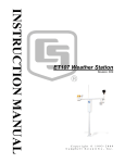
Keyboard
The operator controls the receiver by pressing the buttons and press / turning
the main knob. The buttons are illuminated with LEDs.
The button "ON / OFF" is used to turn the device on and off. As soon as the power supply is connected, the
status LED on the button ON/OFF turns red, indicating that the device is in standby mode. When switched ON
the LED turns to yellow. In case of an internal fault, the device switches off automatically, but the status LED will
still be yellow. To restore power, first switch to stand by (status LED “red”) then try to switch ON again. In case
the device turns itself off several times, pull the mains plug and send it in for repair.
In case you would like to avoid the low power consumption of the device in standby mode, connect the
power cord into an electrical outlet that can be switched off (eg. power strip). All settings are buffered
and protected against power loss.
The number buttons are used to enter decimal values, e.g. frequencies. Pressing a button other than "0" starts
the input mode. During a decimal input, the LEDs of the number keys are lit. Close the input mode with "F1"
(escape = discard the input) or “F4” / "F5" (OK = confirm entry) button. F4 allows the direct entry of a kHz value,
F5 allows a direct input of a MHz value. Example: “1422” and “F4” will set the receiver directly to 1422 kHz. “15”
and F5 will set the receiver to 15MHz or 15000kHz respectively.
The "F1" to "F5" function keys have different functions ("soft keys"), depending of the operating mode of the
RDR54. Their momentary function is shown in the display. There is a basic function and a special function. The
special functions are indicated by the corresponding LEDs being lit. In case a function requires a specific key
operation to be completed, the required key is lit by LED, e.g. in order to tune in to a specific frequency, the
confirm key “F5” is mandatory to complete the operation.
The main knob is used for continuous indexing of values. It features an audible and tactile feedback (the special
version with a magnetic encoder clicks inaudible). Each detent leads to an increase (clockwise) or decrease
(anti-clockwise) of the current adjustment which will be displayed on the screen. The adjustment knob can also
be pressed and then be rotated while being pressed. We will refer to this operation from now on as
PRESS&SELECT. With the knob being pressed you can shift from input tag to input tag, say from demodulator
to bandwidth choice. In order to change a value, let the knob go and now change the setting at will.
The setting of the active entry point can also be done by turning the main knob in the unpressed state: short
press / release à value will flash à turn à stop at the desired location à quick press / release.
The active input marker consists of a color-inverted representation of the value. In the main screen while
selected the text or numeric value is shown in its window in a dark color on a light background, in contrast to the
usual representation of the non-selected values with light colored lettering on a dark background.
Example:
The entry window for "Bandwidth" is now selected, the entry window for "Modulation" is inactive.Speakers and
VERSION
DATE
NAME
English 1.1
13/11/13
B. Reuter / R. Menn
K
RDR54 BA_V300.PDF
Page
13
Headphones
Built-in speaker and connections for stereo headphones and microphone
By turning the knob, the speaker volume is increased (clockwise) or decreased (anti-clockwise). The button has
a detent and no stop. The volume cannot be reduced below zero or increased above the maximum value even
with further rotation of the knob. The knob can be pressed and rotated, in this case only volume of the
headphones will change.
The socket for the headphones (KH) is a 3.5mm or 1/8 inch jack for stereo headphones with standard wiring. All
standard headphones with 16 ohms impedance or above can be connected.
The loudspeaker (LS) can be completely disabled by a software setting (see dialog "Setup"). In this case, the
volume control of the headphones is controlled directly with a rotation of the knob. Pressing the knob is not
needed in this case.
For the use of the RDR54 as a transceiver (“transmit mode”), a microphone socket (MIK, RJ-45, 8-pin) is
provided. Their circuitry and use are described in the section "transmitter module RPA5".
Display
The display is used to display values, the spectrum of
signals and the device status.
The display has WVGA resolution of 800 x 480 pixels. It can display 256 colors and has a non-reflective screen.
The brightness can be adjusted in the Setup dialog.
All operations of the RDR54 (with the exception of the volume setting) are controlled through the selection and
modification of the displayed graphic and numeric values. A screenshot is shown on page 4 of the Chapter
“introduction”. What follow is the explanation of all settings and indicators.
VERSION
DATUM
NAME
English 1.1
13/11/13
B.Reuter / R.Menn
K & M Burkhard Reuter
RDR54_BA_V300.PDF
Page
14
5.2 Receiving frequency
All frequencies are displayed in the SI unit Hz (Hertz), kHz etc. and are separated with the usual colon and dot
for the decimal point. The image shows 11,785,000 Hz or 11,785kHz.
Press and rotate the knob until the color of the frequency window is displayed in reverse color (as shown
above). With the frequency window selected this way each increment of the rotary knob changes the frequency
by the value of the set step size. A direct input via the numeric keypad is also possible (always begin with digit
different from "0"!). Special functions are available using the function keys: the decimal dot and the deletion of
the last digit and the acceptance or rejection of the input.
The display of the frequency itself has a special function: in case your signal exceeds the maximum input level
of the ADC, color of the window (not selected as input set) or the number itself (selected) will turn RED. In this
case, you have to turn on then the attenuator (see dialog "Setup") and / or decrease the input voltage to the
device input!
Settings can be made with an accuracy of 0.5 Hz. There are different setting limits, depending on the selected
filters (see description in "Setup dialog"). Direct entries are rounded to the possible maximum or minimum
value. Rotation of the knob at the region boundaries has no effect.
5.3 Tuning
The step-size for the receiving frequency can be adjusted, can be changed by pressing the "F1" key. Then the
step size display shown below is active as an input window. This is also indicated with the LED of the “F1”
button being lit.
Step-size selection
Now you can change the step size by rotating the knob. The value changes only from a “lowest” digit upwards. It
is characterized by two horizontal bars above and below the selected digit. These bars (and thus the least
significant input digit) can be moved sideways by pressing and rotating the knob. In our example, 5000 Hz is the
selected step increment.
Return to the frequency as the active setting by press "F1" (or "ESC" = Escape). From now on, the frequency
increment when turning the tuning knob is the selected value of the step size (here: 5000 Hz or 5 kHz).
A fast adjustment of the step size is possible if the value contains only one digit (eg. 1,000.0 = 1 kHz): at the
desired position of the bars (in this example the thousands digit) press the desired number button (in the
example "1"). The full value including all zeros will be used immediately and finishes the steps adjustment, a
confirmation with "F1" is not necessary. This way you can quickly switch between standard increments eg. 1
kHz, 5 kHz and 9kHz by simply pressing “F1” followed by the desired number. In short: the key sequence “F1”,
“5” will set the step size to 5 kHz (if the cursor was positioned at the thousands digit).
Special function of the key "0"
VERSION
DATE
NAME
English 1.1
13/11/13
B. Reuter / R. Menn
K
RDR54 BA_V300.PDF
Page
15
The adjustment of frequencies and the corresponding steps can cause slightly offset settings. In this case an
improvement can be reached by pressing the "0" to remove the offset as follows:
•
Frequency values are always set to the nearest lower integer multiples of the corresponding step size,
unless a range limitation is set or a hold function is active.
•
When adjusting the step size, all digits right from the selection bar are set to zero or it will be set to the
lowest or highest possible value of the increment.
This feature allows you to easily correct frequency values after changing the step size or automatically adjust to
the field boundaries.
Example (the "Hz" is not displayed):
Current frequency setting 1,124,550.0 (Hz), the corresponding current step size is set to 10.0 (Hz).
à Adjustment of the step size (by pressing "F1") to 1,000.0 (Hz). If you now change the frequency using the
tuning knob it will be adjusted in 1000 Hz steps, say with clockwise rotation: 1,125,550.0 ... 1,126,550.0 ...
1,127,550.0 and so on.
Your intention in choosing the new step size was probably the desire for tuning the frequency to exact multiples
of the "kHz frequencies". Normally, you had to set such a "straight" frequency by direct input or by choosing a
new step size which is already set. Alternatively you would have to change the step size first back to 10 Hz (50
Hz, 150 Hz or 450 Hz would be more effective) to adjust and "smooth" the frequency and then switch back
again to the 1,000.0 step size.
This effort can be avoided by simply pressing "0" after the adjustment of the step size to 1,000.0 (Hz). The
frequency is now automatically set to the next lower multiple of 1000 Hz, eg. 1,124,000.0 (Hz).
Similarly, the selection of a given step size can be simplified (“F1” is lit). Press and turn the tuning knob shifts
the bars to the left until on or before the first digit > 0 and then turn the knob for a plurality of detent steps to the
left without pressing the tuning knob.
The increment is quickly adjusted to its smallest value "0.5". Now you can re-approach the point that
corresponds to the desired value (keep the tuning button pressed!), for example to the thousands digit. After
choosing the step size (but before finishing the setting using “F1”), Press the "0" key. This also sets the 0.5 Hz
digit to 0.
VERSION
DATUM
NAME
English 1.1
13/11/13
B.Reuter / R.Menn
K & M Burkhard Reuter
RDR54_BA_V300.PDF
Page
16
5.4 Bandwidth
The main display on the screen is the representation of the spectrum ("Spectrogram") of the received signals
within a user selectable frequency range. The RDR54 transfers a 163.84 kHz wide frequency band from the
time domain into the frequency domain thus generating the spectra.
The adjustment of the displayed width of the spectrum is done by selecting the width of the horizontal display
unit, in the example above the value of 10,240 (Hz). On the left the width of a spectral line (1 pixel on the
screen) will be displayed, 320 in our case. The width of spectral lines corresponds to the distance from another
and is equal to the frequency resolution.
On the WVGA display 20 sub-units of each 32 lines (pixels) are available. Accordingly, this represents the
overall width of the display. The frequencies of the first and last line are shown on the top left and right of the
spectrogram. Please note that the counting starts at 0 (the first line to the left) and goes up to 639 (last line on
the right). The receiving frequency is always at the center of the spectrogram (except with demodulator
“EUSB”).
The maximum visible width can be zoomed to the width of the main reception area (see picture above). In this
case the frequencies represent the left and the right side of the spectrum (only 512 lines wide). Any reduction in
the width range is done by bisecting the current width. The minimum width is given by the minimum possible
width of the spectral lines (= highest possible resolution) of 2.5 Hz (RDR50 only 5 Hz).
Within a spectral line, the amplitude attenuation is less than 0.2 dB. The line width of -0.2 dB corresponds to the
distance between the vertical display lines. If a signal is exactly “between” 2 lines, it is shown as two lines of
equal size and with a maximum of 0.2 dB attenuation. There is virtually no "picket fence effect" or similar
artefacts commonly found at spectra generated by Fourier transforms.
Outside of a spectral line, the attenuation increases rapidly and reaches 130 dB at the third line left and right
from the selected frequency. This attenuation is maintained across all lines, there are no spurious resonances
("leakage") or similar artefacts of the Fourier transform.
VERSION
DATE
NAME
English 1.1
13/11/13
B. Reuter / R. Menn
K
RDR54 BA_V300.PDF
Page
17
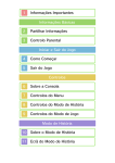
Bin
0
1
2
3
4
dB
Hz
Filter curve of a spectral line width of 2.5 Hz
The lines of the graph of the spectrogram are always drawn so that its visible height exactly equals the value of
the corresponding spectral component. There are no oblique lines drawn (intermediate values with undefined
"interpolated" level).
The frame rate of the spectrogram is directly dependent of the selected resolution. The RDR54 calculates the
spectra using a time sequence corresponding to 4 times the frequency resolution (4x over sampling). There is
no frame rate limitation related to the resolution by principle (as Fourier transform has), just hardware speed
and memory size limits the achievable over sampling factor.
Example:
Resolution 5 (Hz) = 160 Hz / sub-unit à spectrum display frame rate = 20 Hz (images / s = framerate). When
switching to 2.5 Hz “only” 10 frames / s are displayed, when switching to 20 Hz it is 40 frames / s. The maximum
possible frame rate is equal to the frame rate of the display (58 frames / s). Higher transformation rates of the
spectrum are not limited internally (up to 1280 spectra / s) but used for further processing (audio generation or
retention of maximum values) for example.
The maximum spectral width of 163.84 kHz is the constant time-frequency transformed bandwidth of the
RDR54 receiver. All further signal processing (except for FM and AM-wideband envelope demodulation) is done
within this range. The width of the audible bandwidth inside this spectrum is determined by setting the
demodulation filter bandwidth.
Audio bandwidth window
In the spectrogram two small vertical lines indicate the limits of the audible range. Signals within this section are
shown in light yellow, inaudible signals outside the selected range are shown in light red.
VERSION
DATUM
NAME
English 1.1
13/11/13
B.Reuter / R.Menn
K & M Burkhard Reuter
RDR54_BA_V300.PDF
Page
18
The position of the bandwidth can be shifted from the symmetrical position to the receiving frequency by the
setting value "PBT / Shift" (also known as “Passband Tuning”).
Value of the passband shift
Bandwidth and Shift can be adjusted in increments which are dependent on the respective demodulator. In the
demodulators "Auto" to "CW" step size can be set from 20 Hz up to a bandwidth of 10 kHz, with larger
bandwidths 40 Hz. Note, in double-sideband demodulators the increments are applied to both sides. Bandwidth
can be adjusted down to almost twice the minimum possible spectral line (5 Hz at RDR50) and up to about 20
kHz (double-sideband AM).
The "filter edge" of the audible range and the attenuation of the non-audible range correspond to the values of
the spectral lines used. They can be read from the diagram above by multiplying the values by 8 (20 Hz audible
resolution) and 16 (40 Hz). At bandwidths below 40 Hz in each case the values of the next lower level, ie at 5 Hz
bandwidth (absolute minimum) the audible filter response is the original 2.5 Hz line shown above.
In the other demodulators, there are fixed bandwidths (generally 4 selections: 5 kHz, 7 kHz, 10 kHz and 14
kHz). In these demodulators frequency shift is not possible (value is always set to 0). Slope and attenuation of
the filters are generally lower than the spectrum-based demodulators.
For FM-W selectivity-optimized versions exist with a steep edge filter and distortion-optimized versions by
Bessel functions, ie, with relatively flat and "round" filter curve. The filters with a steep edge are referred to as
"S", they should be used mainly for mono reception. The filters for high-quality stereo are our "HQ" versions.
The following filters exist in software version 300 (may vary in further versions, "k" in the name stands for
"kHz"):
•
•
•
•
•
•
•
•
50k S
50k HQ
80k S
80k HQ
120k S
120k HQ
240k S
240k HQ
The effect of various filters on the signal quality can be determined by using the test generator (see "Special
Features" with sample diagrams).
5.5 Demodulators
The type of acoustic playback of the received signal ("mode") is determined by the demodulators. They produce
sound from the spectra of the received signal ("Auto" to "CW"), or from the signal itself (all other demodulators).
The audible signal corresponds to the desired modulation type.
The demodulators can be chosen by toggling in the Modulation window.
•
SYNC: Automatic detection of an amplitude-modulated double-sideband signal with carrier (A3E, AM radio
stations).
The demodulator continuously determines the spectral line with the highest level within the audible range
and interprets it as a carrier. The associated frequency is defined as the carrier frequency of the entire
signal within the passband display; all other signals are viewed as sidebands and processed accordingly.
Once a carrier is detected it is approximately 1 second "held", even if other signals reach temporarily higher
values. Carrier frequency changes will be immediately "rejected" and resynchronized.
•
DSB: Double sideband signal with no carrier evaluation (A3E).
The channel processes all signals such as the carrier would be exactly on the center line of the
spectrogram and generates the audio signals corresponding to the distance and level of the spectral lines
VERSION
DATE
NAME
English 1.1
13/11/13
B. Reuter / R. Menn
K
RDR54 BA_V300.PDF
Page
19
from the center line.
•
LSB: "Lower Side Band", lower sideband of a SSB signal (J3E):
The demodulator generates audio signals corresponding to the distance and level of the spectral lines from
the center of the spectrogram to the left boundary line of the bandwidth.
•
USB: "Upper Side Band", upper sideband of a SSB signal (J3E):
The demodulator generates audio signals corresponding to the distance and level of the spectral lines from
the center of the spectrogram to the right boundary line of the bandwidth.
•
EUSB: "Enhanced Upper Side Band", true image or upper sideband of a very low frequency signal:
The demodulator generates audio signals corresponding to the distance and level of the spectral lines from
the most left line (may be 0 Hz) of the spectrogram to the right boundary line of the bandwidth.
•
SBCW: "Single Side Band + CW", automatic selection of the sidebands at 10 MHz:
The demodulator generates audio signals corresponding to the distance and level of the spectral lines from
the center of the spectrogram to the left (receive frequency below 10 MHz) or to the right (receive frequency
greater than or equal to 10 MHz) boundary line of the bandwidth. At the same time when operating as a
SSB-transmitter (with expansion module) the emission of a keyed CW signal within the sideband is
possible.
•
CW: "Continuous Wave" Morse (A1A):
The demodulator produces an audio tone with the level of the spectral line directly on the
center line of the spectrogram and an adjustable value of the "Shift" ("CW-Pitch") frequency.
For CW, the window changes from "PBT / Shift" to "CW-Pitch."
Note: Depending of the modulation type "SYNC" to "CW", only bandwidth and shift can be changed, as the
selected sideband position allows. For example at LSB, no adjustment is possible so that signals could be
heard right from the center line of the spectrogram.
•
FM-N: Narrow Frequency Modulation (F3E):
The audio is generated directly from the signal of the ADC with a maximum bandwidth of 14 kHz.
Suitable for FM signals with a deviation up to ±5 kHz.
•
FM-W: Wide Frequency Modulation, with optional stereo multiplex decoder (F3H):
The audio is generated directly from the signal of the ADC with a maximum bandwidth of 300 kHz.
Suitable for FM signals with a deviation up to ±75 kHz. In this demodulator a stereo decoder for FM radio
signals can be activated by pressing “F5”.
Note: The stereo decoder generates the left and right audio channel from the spectrum of the demodulated FM
(MPX) signal. Therefore, in stereo no view of the RF signal in the spectrogram is possible. Instead, the MPX
signal is presented in the spectrogram. In order to view the FM modulated RF signal, switch off stereo.
•
IFIQ: Direct output of the received signal to an intermediate frequency:
The signal from the ADC is frequency-shifted and output as a complex signal (I and Q channel) on the
headphone jack. The bandwidth is approximately ±14 kHz around a 10.24 kHz intermediate frequency.
•
BAlQ: Direct output of the received signal in baseband:
The signal from the ADC is down converted and output as a complex signal (I and Q channel) on the
headphone output. The bandwidth is approximately ±14 kHz with 0 Hz intermediate frequency (baseband).
Note: These two demodulators allow the output of a signal for further processing, eg by means of sound card /
PC. The two stereo channels are used to represent the in-phase and quadrature signal of the complex signal
output. The purpose is to enable further demodulation, such as DRM.
•
AM-E: Double-sideband AM with carrier (A3E), envelope detection:
The demodulator generates audio directly from the signal from the ADC whose amplitude response is
the shape of the envelope (peak amplitude, magnitude). It does not work spectrum-based on
discrete frequencies (such as "SYNC") and allows for a good reception and excellent sound with low
distortion in the case of strong and stable signals. Please note that the selectivity is much reduced
VERSION
DATUM
NAME
English 1.1
13/11/13
B.Reuter / R.Menn
K & M Burkhard Reuter
RDR54_BA_V300.PDF
Page
20
compared to the other AM-demodulators.
Depending on the selected demodulator various other settings such as bandwidth and shift are saved and
restored when switching the demodulator. In order to change the demodulator every time other values have to
be adjusted.
Example: SYNC bandwidth shall be 6 kHz, DSB, LSB and USB only 3 kHz. Without the storage of this settings
related to the demodulator the same value is present every time. One would have to adjust the bandwidth at
every switch from SYNC to SSB and back again.
The automatic settings storage is not for each demodulator, but in 4 groups of demodulators:
1A.: SYNC
2.: DSB, LSB, USB, EUSB, SBCW, CW
3.: FM-N, IFIQ, BAlQ, AM-E
4.: FM-W
For the notch filter (see below) there is a demodulator-dependent storage as follows:
1A. SYNC, DSB, CW
2.: LSB, SBCW when frequency <10 MHz
3.: USB, EUSB, SBCW if frequency >= 10 MHz
All other demodulators do not support a notch filter.
5.6 Notchfilter
The notch filter is used to filter-out one narrow band signal within the passband for the suppression of interfering
signals. The width of the filter and its position can be adjusted relative to the receive frequency. The notched-out
frequency range is shown as blue color column in the spectrum.
Settings and display of the notch filter.
The relative position is converted into the absolute frequency in the passband and then stored. It remains when
adjusting the receiver frequency, even if the filter area (relative position) falls outside the passband. In this case
the setting of the position is limited to the maximum positive or negative value corresponding to the bandwidth.
Due to storage of the absolute frequency, the setting can be automatically restored if the receiver is tuned so
that the notch filter falls in the audible range again ("semi automatic" filter, tracking of relative position).
VERSION
DATE
NAME
English 1.1
13/11/13
B. Reuter / R. Menn
K
RDR54 BA_V300.PDF
Page
21
Only when the position is changed manually, the absolute frequency is newly calculated and stored.
The filter has the same damping characteristics as the bandwidth: within three 20(40)-Hz spectral lines it
reaches an attenuation of more than 130 dB. At a setting of the filter width of 120 (240) Hz or wider a signal is
almost completely suppressed in the middle of the notch filter.
5.7 Level scaling and gain adjustment
The level scaling of the spectrum is displayed on the right side of the spectrum diagram.
Display / set the value for the upper limit of the spectrum (in dBm, here +20dBm).
Display / set the scale per sub-unit, resolution is always 40 lines (pixel) per sub-unit.
Display of the lower limit of the spectrum and the level measurement unit.
The vertical position of the spectrum can be changed by selecting and changing the value for the upper limit and
the value of the resolution for the scaling per sub-unit. The unit of measurements can be switched in the Setup
dialog between dBm and dBµV.
In the spectrogram two horizontal marker windows are displayed. Their content refers the values of the "RF
Gain" (manual gain control) or "AGC Limit" (automatic gain control), and "RF Threshold".
Setting and display of the lowest and highest audible level.
The lower marker (blue) indicates the signal threshold above which a signal is audible. All signals whose level is
less are inaudible.
The upper marker (purple) indicates the signal level that produces the maximum level of the audio signal.
Signals above this marker are limited (or distorted). Internally, the RDR54 works with a 6 dB safety margin
("headroom"), so that in case of low clipping distortion does not occur immediately.
VERSION
DATUM
NAME
English 1.1
13/11/13
B.Reuter / R.Menn
K & M Burkhard Reuter
RDR54_BA_V300.PDF
Page
22
The marker can be moved by selecting its value. Direct input using the numeric keypad is also possible.
Since the upper marker can be seen as the RF gain of the receiver (compared to analog receivers), it can be
adjusted by manual operation, or as an Automatic Gain Control threshold. The mode is selectable in the Setup
dialog. In automatic mode, the hold time used to set the marker position lower and the speed of the marker
shifting downwards after the holding time (compares to "Decay" in an analog receiver) can be varied within
wide limits. The movement upwards (= "Attack" / "Desensitization") always happens immediately upon detection
of a higher level and the associated signals are processed only after the shift. The automatic mode thus
prevents clipping.
Attention! The automatic control responds only to signals which are inside the passband (yellow lines in the
spectrum)! Signals shown in red, (that is outside the passband or within the notch filter) will not affect the
marker position. However, since these signals are not processed, they can not cause clipping.
When manual control is selected the top marker describes how by many dBs a received signal on the marker
line has to be amplified to reach 0 dB (full scale) of the audio signal. This "0 dB" audio level relation to the 0
dBm RF level, is not an absolute value in dBm or dBµV because the audio signal is not generated in a welldefined impedance environment and is far more than 1 mW (0 dB audio = about 5 Vpp at headphone and 10
Vpp at speaker output). The gain value of the upper marker is to be considered a relative value.
In automatic mode, this marker is moved by the RDR54 itself. It automates the process of gain regulation. As a
result, the AGC level is closely monitored and provides usable adjustments of the control parameters. The
setting for the upper marker is a control limit (maximum gain) to prevent excessive gain. This limit can be set
directly in dBm / dBµV as it relates to the received signal. It is a useful control to limit excessive gain chasing a
signal into noise which results in listener audio noise fatigue.
When using the FM demodulators, the markers work differently:
•
FM-N: The signal for the narrow FM demodulator is used under the following scheme:
The lower marker receives the sum of all the audible signal spectral lines. It must be positioned above the
visible signal spectra lines for its function. The upper marker determines gain / control limit. However, since FM
is an amplitude suppression modulation scheme, the gain is not critical to the demodulation process. Only when
there is too little gain (near the top marker, signal is very small) will the demodulation be aborted. The top
marker can thus be used as a "noise gate" or "squelch". Set it so that unmodulated noise is not demodulated
and the demodulation starts only at useful signals.
•
FM-W: The signal for the wide FM demodulator is used prior to gain regulation.
The FM-W demodulator has a special algorithm for very high amplitude suppression and therefore requires no
gain regulation. The lower marker can be used for a "mute" function.
In stereo mode, the MPX signal is used for spectrum generation. Now the upper marker has again the function
of the gain control / regulation. But only for the decoded left and right audio channels, not for the RF or the MPX
signal. For more information look on the description of the extended FM advertisements.
5.8 Noise reduction DNR
"DNR" stands for "Dynamic Noise Reduction", the noise reduction system of the RDR54.
A setting other than zero sets various algorithms with different levels of efficiency in operation. Basically, the
effect of the DNR setting is programmed so that each decade (10-place of the setting) calls a different algorithm
or a combination of multiple algorithms; within each decade the effect is 10 – 100% adjustable. For the type and
number (max. 10) of the programmed algorithms, refer to the technical data.
Attention! The setting of the noise reduction system has a major impact on audio quality! In addition to the
planned reduction of noise the quality of usable signals is also affected. Set the noise reduction system only
VERSION
DATE
NAME
English 1.1
13/11/13
B. Reuter / R. Menn
K
RDR54 BA_V300.PDF
Page
23
when needed to values greater than 0 and find an experimental setting that comes closest to your needs.
5.9 Noise blanker NB
In addition to the dynamic noise reduction system "DNR" the "NB" (Noise Blanker) is available for impulse noise
reduction. This system recognizes signal glitches (eg, discharge, ignition interferences, voltage spikes caused
by switching, ...) by their typical fast signal rise and their broadband frequency spectra respond.
The noise blanker benefits from the spectrum-based operation of RDR54. The signal processing is performed in
the entire spectral range of around 164 kHz width, which is separately examined in eight broad areas of about
20 kHz slices. The recognition is always in the region with the lowest signal level to avoid being influenced and
overlapped by strong useful signals.
If a glitch is detected, instead of the desired data signal, a special identification signal is forwarded to the audio
module (FDA20). This adds a replacement signal instead of the glitch in the generation of audio for speakers
and headphones. There is no processing to decrease or mute the original (faulty) signals.
A replacement signal which is inserted in place of the faulty original signal can be calculated, because at the
time of interference occurrence the complete spectrum of the useful signal is known. The last undisturbed
spectrum contains all the signal components to continue the production of the currently active audio signal,
including all frequencies and amplitudes. After the end of the interference pulse the signal generating proceeds
with the calculation of the audio frequencies from the first click-free available spectrum again.
The substitute signal does contain all signal frequencies and their amplitudes at the beginning of the
disturbance. This spectrum is put out statically for the duration of the disturbance. On the other hand a "normal"
signal is a dynamic ever-changing spectrum. The replacement bridges the glitch thus; although this signal is a
signal similar to the wanted signal, this similarity is reduced with the increased backup time. It is therefore all the
more (annoying) audible, the longer the glitch. A particularly good replacement coverage results for in spectra
with few, slowly changing signals (ideally sinusoidal tones such as CW, less dynamic music), and is not as so
good for at speech or noise.
The noise blanker has two settings:
•
Level: This value with a variable 0 to 15 defines the threshold level and the signal slew rate at which a signal
is to be classified as a glitch.
•
ms: Duration of inserting a substitute signal in place of the original signal.
The level value is a level setting of the noise blanker sensitivity. It displays in red during blanking. The higher the
score, the more sensitive the blanker classifies signals as a nuisance. "0" is no blanking and at "15" already
increased noise or a weak signal with a wideband modulation is defined as a disturbance.
The "ms" value specifies the duration in milliseconds, during which a replacement signal is inserted in place of a
detected fault. It is limited to 99. At the latest, after 99 ms a spectrum from the received signal will be generated
before re-inserting a replacement signal is possible ("not re-triggerable" noise blanker).
Follow these steps to set the best functionality as follows:
-
Place a temporary blanking setting: Common problems require about 50 ms for double sideband
modulation and CW reception ("SYNC" or "DSB" and "CW") and 70 ms at single sideband ("LSB", "USB",
“EUSB” and "SBCW").
-
Increase the level value from 0 to such an extent that the instantaneous received signal triggers the noise
blanker. You can see this on the flashing red digits of the level value and the audible signals from
substituting the original signal ("machine noise" from fast following blankings).
VERSION
DATUM
NAME
English 1.1
13/11/13
B.Reuter / R.Menn
K & M Burkhard Reuter
RDR54_BA_V300.PDF
Page
24
-
Now reduce the level value by a few steps, so that an undisturbed useful signal no longer triggers blanking.
Depending on the type and strength of impulse noise the duration may be adjusted. It should be as short as
possible to just bypass the glitch. The level value may need to be changed slightly depending on the received
signal, because of the many simultaneous signals in the total range of 164 kHz (eg, tuning the receiver to the
middle of a heavily occupied broadcast band) can cause unwanted triggering of the blanker.
The noise blanker also protects the system from interference signals. If the blanking time is set correctly, after
the glitch the full receiver sensitivity is immediately available again .
The AM-E and the FM demodulators can not produce substitute signals. Disturbances in the FM mode, of
course, has less effect on the signal quality. By using the system as an FM squelch unwanted noise can cause
an increase in the squelch sensitivity. In this case use the AGC manual control or the lower marker ("threshold")
for reducing audio noise.
5.10 Videofilter
Function key "F2" allows (except for direct frequency entry) the insertion of a filter function in the image
processing of the spectrum display. This can be changed by repeatedly pressing the button between no
filtering, average filtering and maximum hold function.
•
No: In case a high temporal resolution of the display is needed, the video filter should be switched off. The
display will show a very highly dynamic image, with every change in the level (noise) displayed exactly as
recorded.
•
AVG: Average of the spectral curves of multiple images. The displayed noise will be reduced as short-term
maximum and minimum values do not appear in the display.
•
MaxHld: The spectrum shows the highest value recorded since the last reset of the display. Here all the
detected values are recorded at full processing speed, even if this is above the frame rate (vertical period)
of the display, so the actual maximum value might normally not be seen in the display. Adjustment of the
maximum hold time can be adjusted for measuring and monitoring purposes.
If you select this filter, the reset rate can be changed via a setting below the caption for key "F2". It can range
from 0 (= reset for each new line) up to 9.8 s and then can be set to "infinite". When the reset time elapses all
spectral lines will be reset to a zero value. Immediately after this the spectrum starts collecting the new
maximum values and will “grow up” until the next reset occurs.
Defines the maximum hold time for an unlimited measurement.
The unlimited measurement time allows the detection of transient signals (monitoring function), which are then
displayed as long as desired.
Attention! Any change in the measurement period or the filter function leads immediately to a reset the display!
5.11 Surround sound
The RDR54 has 2 audio channels that can operate independently within the 164 kHz receiver bandwidth. From
the user interface 2xx version on, the second channel is phase shifted receiving the same signal as the first
VERSION
DATE
NAME
English 1.1
13/11/13
B. Reuter / R. Menn
K
RDR54 BA_V300.PDF
Page
25
channel (which is always audible).
Channel 2 can be set via softkey "Surround" (pressing the "F5") on the right headphone channel, channel 1 is
then only heard left or through the loudspeaker. This increases the audible signal level, but not the noise. The
signal intelligibility is improved by the stereo-like sound even further.
The effect of the "surround sound" feature is strongly dependent on other settings. In certain settings, a good
effect can be achieved. In addition to bandwidth and shift the exact tuning is primarily of importance. Even a
small change in the reception frequency can change the effect, just as the change in the frequency position of
the calibration (see the "Memory” dialog). Try different settings if necessary.
When the demodulator is "FM-W" the key is labelled “Stereo” and activates the stereo decoder for a FM radio.
5.12 S-Meter
In the upper panel of the display there is a S-Meter, which is similar to those in analog receivers.
The instrument shows on two scales (above S values with decimals, and S9 +xdB or S0 -xdB, down scaling in
dBm or dBµV) the current level inside the audible frequency range with a fast "pointer". To the right there are
the smoothed averages (0.8 s) displayed as a digital value. The purple number value indicates the current
position of the control / gain setting (upper horizontal line marker). The current unit of the numerical values is
also displayed; they can be selected in the "Setup" dialog.
The measured values for the S-Meter can be derived directly from the spectrum. Here the video filtering has to
be taken into account, so the unfiltered value, average, or the currently accumulated maximum value is
displayed.
When selecting a CW or SSB demodulator, however, it is always a "quasi-peak” reading. Each detected peak
value is displayed for a short time, then the value slowly fades down to the current signal level.
VERSION
DATUM
NAME
English 1.1
13/11/13
B.Reuter / R.Menn
K & M Burkhard Reuter
RDR54_BA_V300.PDF
Page
26
6. Dialogues
In addition to the permanently displayed user interface, different "windows" or "menus" are available, in which
further additional options can be chosen. Those temporary views are called "dialogues".
If a dialogue is opened it changes the function of the control knob from the currently active setting function on
the main display to the chosen setting function within the dialogue. The navigation and selection process is the
same as with the normal user interface: a selection can be made with the main tuning knob being pressed to
skip from option to option. Once you have chosen your option, you can change the value / setting within the
option windows by simply turning the main tuning knob.
In contrast to the normal display window color scheme, colors in dialogues are inverted once they have been
chosen. Color highlighted values allow a change in the auto-encoder mode (see description in "Setup dialog").
6.1 Setup dialog
Pressing "F3", the dialogue "Set Up" will appear, the spectrum display will be stopped and the dialogue box is
shown in the display like this:
In the Setup dialog most basic settings of the device's functionality can be set, their adjustment during normal
operation is rarely necessary.
The current status of these values is always visible in the user interface on a panel at the bottom of the screen.
The individual values are as follows:
VERSION
DATE
NAME
English 1.1
13/11/13
B. Reuter / R. Menn
K
RDR54 BA_V300.PDF
Page
27
•
Handwheel Automatic
A value from 0 (“Off”) to 14 sets the rotational speed of the tuning knob and automatically forces the adjustment
without the need of user intervention. 0 is OFF, “1” is the lowest speed (very slow rotation) and 14 the highest
speed required to trigger the automatic mode.
The system monitors the movement of the tuning knob and takes over its function, once a certain minimum
number of pulses per second detected. If this detection threshold is exceeded, the automatic system inserts
virtual encoder pulses as sent by the keyboards operating system. These pulses cause exactly the same
function (change a setting) as the operator would do using the control knob then tuning a frequency for
example, it will have a flywheel effect.
The purpose of the process is to continue a running adjustment, even if the operator has stopped turning the
knob. It tries to detect automatically the rate of adjustment in accordance to the measured rotational speed of
the knob which is turned by the operator. Once the rotation of the knob is started, the adjustment of the selected
value is automatically triggered.
Once the automatic adjustment has taken over the knob function, it clearly indicates this by flashing a red icon
in the lower panel of the display:
The automatic encoder is active.
The arrows to the left and a minus sign indicate the direction of the ongoing adjustment towards lower values
(knob was turned anti-clockwise), and the ">" character and "+" symbol accordingly to higher values (knob was
turned clockwise).
At low values of the auto setting (activation already at low rotational speeds), first a small increment is set, at
higher values of the automatic accordingly higher increment (values will change faster).
During the automatic adjustment, the operator can always increase the adjustment velocity by further rotation of
the tuning knob in the current direction. The automatic mode detects these pulses and correspondingly
increases the speed up to a maximum specified by the device (depending on the set about 10 - 100 pulses per
second).
If the operator moves the rotary knob in the opposite direction, the automatic is immediately interrupted and the
adjustment by the user in the opposite direction is executed. Effectively, therefore, the last automatic pulse is
reversed.
The automatic mode is also stopped under the following circumstances:
•
Any key or the tuning knob is pressed.
•
In case it will reach a final value of a setting (sometimes not fully visible)
•
The upper horizontal marker (manual gain control or automatic gain control) is moved at least one position
up or the received signal exceeds the marker within the audible area. This is especially helpful when tuning
a frequency, as it is immediately turned off in case a strong signal comes into the audible reception area.
•
Request for a display scan through the USB interface.
The hand wheel automatic mode is not available for all adjustments, but only for those with more than about 20
possible values. In dialogues, these values are highlighted in light colors.
VERSION
DATUM
NAME
English 1.1
13/11/13
B.Reuter / R.Menn
K & M Burkhard Reuter
RDR54_BA_V300.PDF
Page
28
•
Deadtime Handwheel Switch (ms)
When pressing and releasing the adjusting knob (pressing the internal mechanical switch), an occasional
accidental click step is sometimes carried out. This happens especially with magnetic latching rotary encoders,
since they have a very "soft" cogging and no audible snap sound.
For the rotary encoder button, a "dead time" needs to be set. If the knob is pressed or released, the rest steps
are then only allowed after the time lag. Those steps that happen during the dead time are ignored.
The time delay also acts "backwards", ie for rotations before pressing / releasing the main knob. If this press /
release occurs within the dead time since the last rotary motion, then the last executed steps (which occurred
due to the rotation) will be undone.
Select a value for the dead time to remove accidental steps that occur in setting procedures when you press
and release the knob. This value is depending on personal feeling and skill, the built-in encoders and practice in
the device operation.
Note: A high value requires a long wait for rotations or press / release, before you can continue to operate!
Otherwise, the final intended use is always made undone, which is also undesirable.
•
Display Diagram
-
Curve Spectrum: The spectrum is shown as a connecting line between the level values in each spectral line.
The usual representation of a spectrum.
-
Line Spectrum: Each spectral line is drawn from the lower boundary up to its level value (equivalent to "fill"
the display below the curve spectrum).
-
Waterfall: The spectrum is shown as a waterfall diagram.
So-called "waterfall plots" are an important tool for recording and documenting signal changes over time. Thus,
each recorded two-dimensional spectrograph will not be displayed with the frequency on the x-axis (horizontal)
and the signal level on the y-axis (vertical), each new plot overwrites the old one immediately and irrevocably.
Rather, the level meter will now be scaled to almost the depth level (z-direction). Since this third dimension in a
graph is not possible or representable, the level is now coded in colors and the spectrum is written as a onedimensional line in the diagram.
Imagine you would take the usual spectrum display into your hands, turn it by 90° around the horizontal axis with
its “tips” directed to you. Now look down to the edge of a thin "spectrum-slice" where the parts closer to you are
bright and the tips further away from you (valleys) are in darker color.
This slices are now continuously drawn in the display, older slices moving downwards, while newer slices
appear at the top of the display. The newest one is always drawn on top, the oldest slice disappears below the
diagram.
VERSION
DATE
NAME
English 1.1
13/11/13
B. Reuter / R. Menn
K
RDR54 BA_V300.PDF
Page
29
The effect corresponds to a visual impression of a waterfall, hence the name of this display.
The "fall velocity" can be selected in three steps.
The diagram is moved at a speed of 0.7 sec / unit = 17.5 ms / line (spectrum).
Note: The calculation speed of the spectra is independent of the selected running speed and always equal to 4
times that of the selected spectral line width, in the example shown, ie 1280 spectra / s = 0.78125 ms /
spectrum. To prevent data loss, select the mean or at very high data rates (for example) the maximum value for
the video filter. Set the refresh rate to somewhat higher values than the line speed of the waterfall's one. If
necessary, increase the line speed to the maximum value (0.35 s / unit = 8.75 ms / line).
Conversely, at high resolution and correspondingly lower spectra rate per second, possibly less calculated
spectra are plotted as lines are drawn. That causes no data loss, but the plot is less informative, as more and
more lines are drawn with the same content in succession until a new spectrum is available. In this case, reduce
the speed of the Waterfall chart and / or turn off the video filter.
The view of the waterfall is heavily dependent on the "viewing depth" of the underlying level position in the
diagram. The indication of the level takes place as color coding. Which colors are used for each level is shown
in the color chart.
The color chart shows the representation of the signal level in color steps.
The colors displayed correspond exactly to the magnitude of the normal spectrum display and can be altered as
well. The colors themselves can not be changed.
VERSION
DATUM
NAME
English 1.1
13/11/13
B.Reuter / R.Menn
K & M Burkhard Reuter
RDR54_BA_V300.PDF
Page
30
Note: Select the level position of the spectra (selecting the upper setting value) for the highest possible contrast
so that the area of your level of interest is displayed in large color differences. For example, the noise threshold
should be adjusted so that already little peaks of a signal are coded as a next color step. This way even low
signal levels result in a clearly visibility trace above the noise floor.
-
Oscillogram (FM-W only): shows the diagram of the timeline (not of the frequency domain as spectrograms)
of the output signal of the stereo decoder.
The oscillogram records the time line of the amplitude of the LF signal. On the left side to the center the left
channel is shown, on the right side the right channel. The horizontal scale is now in units of time (rather than
frequency), the vertical scale corresponds to the amplitude represented by the deviation of the original FMmodulated signal.
The adjustable time scale lets you select various sampling rates and thus the "stretching" or "compression" of
the diagram in the horizontal direction.
The unit "kHz" for the amplitude results from their direct proportion to the deviation of the FM signal. Here, a
signal represented by "0 kHz" (vertical center of the diagram) is the demodulated value at exactly the carrier
frequency, amplitude values are indicate exactly above or below the current modulation of the FM signal. The
oscillogram can therefore be used for the modulation measurement.
The oscillogram is "DC-coupled”, any deviation of the RF signal from the exact carrier frequency causes a
vertical displacement. It can thus be used as "tuning aid" for FM signals.
Note: The oscillogram, in conjunction with the stereo test generator (see section "Special Features"), can be
used for the measurement of channel-crosstalk.
-
Goniogram Line (only FM-W): Phase diagram of the output signal of the stereo decoder.
VERSION
DATE
NAME
English 1.1
13/11/13
B. Reuter / R. Menn
K
RDR54 BA_V300.PDF
Page
31
The Goniogram draws a diagram of the time-dependent spatial (two dimensional) amplitude and phase
distribution of left and right channels. This gives the deflection in the horizontal (x-) direction, the amplitude inphase signals (sum or mono signal), the deflection in the vertical (y-) direction, the amplitude of unequal phase
signals (differential or stereo signal).
The scaling of the x-axis shown here is incorrect, it is just like the y-axis the amplitude represented by the
modulated signals deviation. The x-axis settings were left for the sake of clarity, as in the oscillogram. Even
here they are again setting the sampling rate (time between two samples).
The Goniogram always consists of 512 samples of left and right channels. The coordinates of the continuous
samples are shown as a line from the last to the current sample. After 512 samples, the resulting line is deleted
and the drawing of the next starts.
Note: When using the maximum-hold video filter (as shown above), older lines are not deleted immediately, but
during the measurement period of the filter shown in blue. The current drawn is always shown in yellow (or
green). As the drawing process is very rapid, with the maximum-hold a longer storage and visualization of the
obtained amplitude values is possible. The same applies to the oscillogram and the histogram.
Note: The Goniogram, in conjunction with the stereo test generator (see section "Special Features"), is useful
for a variety of measurements and signal representations ("Lissajous figures"). In particular, the filtering
properties of the receiving channel from the ADC output to the stereo decoder can be assessed in terms of
amplitude and phase distortion well.
-
Goniogram Dot (FM-W): Phase diagram of the output signal of the stereo decoder.
As above "Goniogram Line", the coordinates of the samples are shown but only as individual dots and not
continuously connected with a line.
VERSION
DATUM
NAME
English 1.1
13/11/13
B.Reuter / R.Menn
K & M Burkhard Reuter
RDR54_BA_V300.PDF
Page
32
-
Histogram (FM-W): Time / amplitude diagram of the output signal of the stereo decoder.
The histogram is a "waterfall graph" that runs from the right (present) to the left (past). It shows the timedependent amplitude of the modulation level for the resulting audio (L and R are added).
The vertical scale in dB is the audio level at the time. "0 dB" means a nominal modulation at 75 kHz deviation,
taking into account the (stereo) Pilot and RDS signal (standard signals of an FM broadcast station).
The speed of the histogram can be selected with the horizontal scale. There is also a possible stop (value is
shown as "STOP!"). The absolute times (orange numbers) are then represented in negative times (as past).
When restarting, the time on the left side is immediately scaled proportionally to the present and is false as long
as all the old lines (from the downtime) are overwritten.
Note: The histogram can be used to judge the quality of the modulation when using dynamic compressors and
exceeding the permissible modulation swing.
Note: In the histogram the current position of the top horizontal marker appears. When using this diagram, the
marker acts contrary to the common RF level adjustment. That is, levels less than 0 dB will be reduced the
farther away they are from the 0 dB mark (decompression). The effect depends on the setting of the diagram
and can generally be varied by changing the "DNR" setting of the user interface (at FM-W this setting is labelled
"DCM" for "decompression mode"). Setting to zero prevents any signal degradation.
•
Loudspeaker
The internal speaker can be permanently muted ("Off", useful for pure headphone use). If the speaker is muted,
the volume knob to change the headphone volume does not need to be pressed.
•
Display Brightness
Adjust the brightness of the display and the keyboard-LEDs in steps from 0 – 100. Settings below step 5 at
“power on” or “accessing a memory” will be set to 5.
VERSION
DATE
NAME
English 1.1
13/11/13
B. Reuter / R. Menn
K
RDR54 BA_V300.PDF
Page
33
•
Level Units
Scaling (y-axis) of the spectrum or waterfall chart and the S-Meter in dBm or dBµV.
•
Vertical and horizontal grid lines
Dotted lines in the spectrum graph to better view the sub-units.
•
RF Gain Control
-
Auto: The gain of the received signals (and thus the volume of the audio signals) will be adjusted
automatically.
-
Manu: The gain can be adjusted manually by moving the upper horizontal marker.
•
Holdtime (s)
The time between detection of a reduced signal level in the spectrum up to automatically increase of gain in
automatic control.
•
Attackrate (dB / s)
Speed at which the upper marker in order to increase the gain is adjusted automatically.
•
ANT1 Highpass (kHz)
Into the signal path of "ANT1", a coupling capacitor to increase the lower limit frequency is activated. By default,
a capacitor for a lower cutoff frequency of about 1 kHz is available. In addition, a capacitor of about 75 kHz cutoff frequency can be switched on (loss of audio signals and especially mains hum).
•
Preamplifier 0 – 54 MHz (dB)
Into the signal path of "ANT1" and “ANT2”, an about 15 dB amplifier for decreasing the noise levels can be
switched on. Available only for RDR54 version “D”.
•
Attenuator 0 – 30 MHz (dB)
Into the signal path of "ANT1", a -20 dB attenuator for increasing the clipping free RF-level can be activated.
•
Impedance 0 – 30 MHz (ohms)
Into the signal path of "ANT1" a (idealized 0 ohms) amplifier with very low input impedance can be switched on
("Current sensitive input"). Available only for RDR54 version “C”.
•
Filter Highpass / Lowpass (Switching of the high-frequency filter)
-
Auto: Automatically set according to the actual receiving frequency.
Fixed values below 50 MHz: Fixed turning on the appropriate filter.
Fixed value of 50 or 54 MHz (no matter which filter): Fixed filter and use of antenna input ANT2 in the range
50 MHz to 54 MHz.
Fixed value of 87 or 108 MHz (any filter): Fixed filter and use of antenna input ANT3 (only for existing FM
module).
Fixed value of 144 or 148 MHz (no matter which filter): Fixed filter and use of antenna input ANT4 (only for
existing FM module).
-
VERSION
DATUM
NAME
English 1.1
13/11/13
B.Reuter / R.Menn
K & M Burkhard Reuter
RDR54_BA_V300.PDF
Page
34
-
No high-frequency filter connected, except fixed-aliasing filter 31 MHz and input coupling capacitor 1 kHz or
75 kHz.
Note: The RDR54 digitizes a frequency range from 0 Hz to 150 MHz. With only one built-in signal processing
board RDR25 merely an area of 163.84 kHz is used effectively. To avoid interference due to frequency signals
located far away and to increase headroom, various high-frequency filters in the signal path from the antenna to
the A / D Converter are available. In addition to fixed switched filters for the respective frequencies of the
antenna inputs, in the range up to 30 MHz a series of high- and low-pass filters are switched (see technical
data). RDR54 version “D” even includes a tuneable preselector.
The current signal path is displayed by the following graphic.
The left value indicates the current high pass filter, the right value the low-pass filter. In the range of 500 kHz to
18 MHz version “D” shows only one frequency (resonance frequency of preselector). In this case the value can
be altered manually or automatically.
Attention! The range of 50 MHz to 54 MHz can be selected only in the filter-automatic mode by tuning the
frequency into this range (overflow of 30 MHz directly to 50 MHz), or a filter (whatever) is placed on this area (no
overflow of frequency permitted). The same applies to the areas of the FM module.
Attention! Using the filters reduces the measuring accuracy of RDR54! Use it for measurement proposes only
for the 6m (FM) area or in high noisy environments in the range up to 30 MHz.
Attention! When switching the fixed filters on, the accuracy of RDR54 at a frequency setting outside of the filter
area is completely undefined! Likewise, when selecting the high-pass filter 75 kHz in the range below about 100
kHz. The same applies when manually tuning the preselector different to the receiving frequency.
Attention! When selecting the input impedance preamp with 0 ohms, the level of scaling is totally undefined!
•
Audio Highpass (Hz)
Highpass filter for all audio processing. Can be set between 20 Hz and 200 Hz to suppress unwanted low
frequency audio signals (hum and so on).
•
Audio Lowpass (kHz)
Lowpass filter for all audio processing. Can be set between 0,5 kHz and 15 kHz to suppress unwanted high
frequency audio signals (noise etc.).
The Setup dialog must always be closed by pressing the "F3" (key LED flashes with this dialog opened). All
settings in the dialog are stored permanently and their values are now used for the further functioning of the
equipment.
VERSION
DATE
NAME
English 1.1
13/11/13
B. Reuter / R. Menn
K
RDR54 BA_V300.PDF
Page
35
6.2 Memory dialog
The soft key F4 labelled "Memory” brings up a dialogue in which additional device functions can be user
defined. In this dialog the settings for the calibration of the RDR54, parameter storage as well as other device
settings are available. Further, the operation of a test generator for various purposes is possible. With the
Memory dialog open the spectrum display will continue to run.
The following settings are possible:
•
Calibration Oscillator
The main oscillator of the RDR54 can be adjusted. The indicated set corresponds to a dimensionless value that
is used by the adjustment system for calibration of the oscillator. Ask for precise calibration of a well-known
signal (or reasonably accurate frequency standard radio station) with high spectral resolution (optimum 2.5 Hz /
line) so that the frequency corresponds to the center of the spectrum display.
Precise calibration.
Adjust the oscillator calibration in such a way, that the carrier appears as pictured above with exactly the same
level in line 319 and 320 (center line of the diagram). Turn on at least one vertical grid line for identification.
Attention! The setting of the calibration has great impact on the quality of audio production, and the accuracy of
RDR54!
Attention! When selecting the calibration stage "999", a test generator is activated, which sends its signal
instead of the ADC data to the signal processing! For further information see section "Special Features" - "Test
Generator".
-
Level (dB)
An adjustment of this value causes a vertical shift of the display in all spectrograms by the set value and
therefore a change of level readings. Use it when you need to make an accurate level setting using an external
reference.
-
Undo back to level
The device stores the last 63 continuously operating steps you have made. You can always call one of these
settings again (see description of special functions "Undo"). Setting "0" always contains a factory defined default
setting.
-
Save Settings to No.
VERSION
DATUM
NAME
English 1.1
13/11/13
B.Reuter / R.Menn
K & M Burkhard Reuter
RDR54_BA_V300.PDF
Page
36
The current device settings can be saved to one of 63 memory locations permanently. Select a location for the
backup. Any information in former storage in this place appears before anything is saved, or whether it is still
empty. The red marking is used to signal that something might be overwritten! Backups of the complete current
device status are always created without further warning if the dialogue is closed with this setting selected
and pressing the "OK" button (F5)!
-
Load Setting from No.
You can load a saved setting from this memory location. Any information in the stored setting (demodulator +
frequency) appears, if there is a valid setting on the selected location. Otherwise the location is declared empty
or used by other software. Location 0 leads to load a very special setting, the "Boot loader" (see
description of special features: Software Update).
-
AF-Level (%)
If the test generator is activated by choosing setting “999” for oscillator calibration, here the amplitude of the test
signals can be adjusted. If both selected frequencies are greater than zero, the level of both signals is
automatically halved to avoid clipping. For further information see section Special Features "Test Generator".
-
FM Dev (kHz)
If the test generator is activated by choosing setting “999” for oscillator calibration, here the deviation of the
frequency modulation can be adjusted. For further information see section Special Features "Test Generator".
-
Freq L
If the test generator is activated by choosing setting “999” for oscillator calibration, here the frequency of the first
audio signal can be adjusted (usually used for the left stereo channel). For further information see section
Special Features "Test Generator".
-
Freq R
If the test generator is activated by choosing setting “999” for oscillator calibration, here the frequency of the
second audio signal can be adjusted (usually used for the right stereo channel). For further information see
section Special Features "Test Generator".
The Memory dialog has to be closed with either the F1 key (Function "Escape" = Discard the settings) or F5
("OK" = Activate of the settings). To indicate the necessary usage of one of these 2 buttons both key LED
flashes.
Pressing F1 will conduct no further changes in the device setting. However, calibration of the oscillator and level
or frequency settings are always executed immediately after a change of setting inside the opened dialog and
stored permanently. If you press F5 and have select a memory location or an undo level, the function is always
executed: the current instrument setting is saved or restored completely (if applicable!).
VERSION
DATE
NAME
English 1.1
13/11/13
B. Reuter / R. Menn
K
RDR54 BA_V300.PDF
Page
37
7. Special Features
All previously described instrument settings and functions are the appropriate to the use of the RDR54 and will
be required more or less often. Some features are rarely or perhaps never necessary, but must still be
implemented and documented.
The variety of possible settings and operations of the RDR54 can possibly lead to undefined or obscure
settings. Switch-off and restarting the device brings no help in this case: All device settings are always stored
non-volatile, the RDR54 starts again in exactly the same operating state it was on shut-down, even after a long
time with an unplugged power cord.
To set the device to a known operating state, you have several options:
-
The "Undo" function.
The initialisation of a start-up status, called the "factory setting".
The complete deletion of almost all software in the device and (re-) load the old or new software ("Software
Update").
7.1 Undo Function
Use this feature if you ran only a few operating steps that have led to an unsatisfactory or confusing setting state
of the device. You can get back the setting state of the device to one of the last 63 operating conditions. Note
the instantaneous state "Undo Level", which is always displayed in the panel below the spectrum diagram:
The device is currently in state "49".
Now try to define a certain number of operating steps from where you want to undo the settings and subtract
this number from the current state. You have to calculate a possible “underflow” to negative values as the
countdown to the highest possible value of 63:
Example: Current state 8, desired return of the instrument setting of 10 Steps:
8-10 = -2 à (0 corresponds to 63) à 63-2 = 61
Open the Memory dialog. Select the setting "Undo back to level:" and set it to the desired undo state (as per
example "61"). Close the dialog by pressing F5 = "OK". The device is set to the state that existed when the last
time "61" stood in the display.
Note: The Undo value is always incremented by actuation of keys (ie the state of the equipment is stored). This
includes pressing the knob (more precisely, just when releasing it). You can always trigger a complete storage
of the device setting by briefly pressing and releasing the adjusting knob. Remember or write down the
displayed undo state if you think you possibly will reverse the next device setting.
Note: At switch-on the setting of the device is restored to the level displayed when switching it off. If you make a
note of the displayed value immediately after switching on, you can return to this power-on state up to the undosystem overflow (ie the automatic reuse of this space).
The readout of the current undo level has a secondary function: After switching on the device the field is shown
in red for a few seconds. In this time the RDR54 checks all internal components, software and hardware. When
the red marking disappears it signalises the end of this check to be successful.
When you switch off the RDR54 during the check it will remember this as a not successful power cycle. More
then 3 times of such incomplete power cycles causes the start of the Bootloader instead of loading and starting
the common display again. This gives the chance to upload new software in the situation of former falsely
loaded files or any corrupted functionality that denies starting the Bootloader in the normal way (“Memory”
dialog).
VERSION
DATUM
NAME
English 1.1
13/11/13
B.Reuter / R.Menn
K & M Burkhard Reuter
RDR54_BA_V300.PDF
Page
38
7.2 Defaults
Number “0” of the undo function cannot be overwritten and is always containing a clearly defined factory setting.
You can load this setting if you can not find any useful or desirable setting in the undo buffer system.
Note: You can also use manually allocated memories (if used) in order to load custom settings saved by
yourself on a certain place. These memories will not be changed or overwritten by the Undo function.
The factory default sets all the parameters either to its smallest (eg frequencies) value or for a useful operating
condition (eg brightness).
7.3 Software Update
The RDR54 allows extensive customization of functionalities implemented by the programmed firmware which
can always be restored by connecting it to a personal computer (PC). The software creates not only in the
usual sense the "software", say specified programs of microprocessors, but also the configuration files used in
programmable logic devices ("FPGA" = Field Programmable Logic Array à free matrix of programmable Logic
units), thus the existence of complete units such as processors and interfaces within the device (so-called "soft
cores"). Only a few units are designed in “true”" hardware, such as the A/D and D/A converter, power supply or
keyboard controller. Even the WVGA graphics chip is an FPGA, and thus can be software defined from scratch.
-
Bootloader
Upgrading the software uses functions of the device's internal operating system. This is realized by an
interface program, called "Bootloader" (loader for software).
VERSION
DATE
NAME
English 1.1
13/11/13
B. Reuter / R. Menn
K
RDR54 BA_V300.PDF
Page
39
The Bootloader is non-volatile firmware programmed into the signal processing board RDR25 and can be
started by choosing the value 0 of the setting “Load Settings from No.” in the Memory dialog. All currently
running tasks in the device (sub-programs of the various modules) with their identification numbers will be listed,
as well as the stored main programs on the RDR25 card, so-called “Configurations”.
Normally, the card includes one or more configurations for the realization of the device function "RDR54CVxxx",
where "xxx" is a number that describes the version of the user interface. Such a configuration can be removed
by pressing "F3" key, or started by pressing "F5". By pressing "F1" the unit can be restarted without changes,
"F4" transfers functionality of the device to an external program (such as other signal processing boards, which
also contain configurations).
Attention! Never delete all configurations of the device, without being sure to be capable of reprogramming a
new configuration! Should the device (more precisely, the RDR25 module) contain no configuration at all, the
only device function still possible will be to start the Bootloader!
Warning! When you delete a configuration, all subsequent configurations are deleted from the list too! Previous
configurations will remain.
Note: Starting a configuration with "F5" can sometimes lead to incorrect functioning of the equipment (the user
interface RDR54 does not appear in the display). The reason is that some modules (plug-in cards used) require
a power shutdown. Switch-off and turn the device on again after a few seconds in this case.
If even after the power cycle and pressing F5 again no device function (RDR54) can be obtained, the
Bootloader appears again. In this case one / several tasks (a plug-in card) is defective, does not exist or has no
software stored (identification “EType” contains BDxx). Load in the latter case new software as described below.
If this doesn’t help, the device is defective and must be taken out of service. Send it in for repair if necessary to
the supplier / manufacturer.
Software Download
A download (storing) of a new software requires connecting the device to a PC via a USB interface (version
2.0 "high speed" required) and the correct installation of the so-called "device drivers" for recognizing the
RDR54 as a connected USB device. You will need a PC running Windows XP SP2 or Windows 7 32 / 64 Bit!
You should proceed as follows:
-
Insert the included CD-ROM into the CD drive of your PC.
Connect the RDR54 using the supplied cable to a USB port.
Turn on the power.
On your PC an installer (or "wizard") will be started, which asks for the device driver for the RDR54. This
driver is called "CYUSB.SYS", the related information file for Windows "RDR54USB.INF" and is on the CD.
Lead the installation wizard to this file and follow further instructions.
Attention! Driver and PC software for use with the operating systems Windows XP SP2 to Windows 7 are
provided. They assume the correct operation of the PC and the operating system. Depending on the version of
the system, the installation program is different for loading device drivers. Refer to the instruction manual for
problems or help function of your computer / operating system!
Attention! The operating system Windows 7 64 bit needs to be started with disabled driver signature
enforcement to activate the CYUSB.SYS driver!
After installing the driver your PC detects a device "RDR54 (RDR54)". Perhaps a repeated switching on and off
or disconnecting and reconnecting the USB cable is necessary. For uploading and downloading of software
there is a program "RDR25A.EXE” on the CD in the folder "RDR54". Copy this folder with all the files in any
folder of your PC. Start ("Open") the file RDR25A.EXE from this folder. The user interface of the program
appears on your monitor.
VERSION
DATUM
NAME
English 1.1
13/11/13
B.Reuter / R.Menn
K & M Burkhard Reuter
RDR54_BA_V300.PDF
Page
40
In the text box "Device" RDR54 must be displayed. If necessary, you can search through the menu item "USB"
for existing equipment. If there is no entry in the "Device" box, then the USB driver is not installed correctly or
the RDR54 is not connected / switched on. Make sure the receiver is connected properly and check the
installation in the device manager of PC and install the driver manually if necessary!
The firmware to program into the RDR54 always has the extension ". RPD", eg "RDR54CV300.RPD". The CD
contains some of these files. The file whose name always starts with "RDR54" is a configuration file for the
device. In order to load them in the RDR54, proceed as follows:
-
Start the Bootloader (dialog "Memory" à Load Settings from No.: à 0).
Click on the button "Synchronize", a check mark must then appear in the check box "Bootloader active."
Select via the menu item "File" and select "Open" and open the desired file. The file name must appear in
the box "File".
Click in the "Transfer to" box on "RDR25 (Configuration)" if this point is not already selected.
Click in the "Download" box on button "Start". The "Bytes sent" now displays the number of bytes
transferred consecutively.
At the end of the transmission, a window appears indicating the successful transmission.
For errors, a message window appears with a note on the error (eg "Device not responding"). Then turn the
unit off and back on, start the software interface and repeat the entire procedure.
Attention! Do not turn off the device or the PC during the download and never disconnect the USB connection!
Note: If the message "Software can not be saved!" appears, the memory is full, no more configurations can be
loaded. Delete stored configurations in this case (key "F3").
In the Bootloader of the RDR54 the newly loaded configuration is displayed (possibly reset required). The
transferred configurations are stored sequentially. One of them can be selected using the knob and can be
started by pressing the "F5" (possibly turning off and on the equipment is needed).
In addition to the configurations for the definition of device functionality, also all auxiliary functions ("tasks") of
the various modules can be reprogrammed if the hardware allows it. Such tasks can be selected for update by
VERSION
DATE
NAME
English 1.1
13/11/13
B. Reuter / R. Menn
K
RDR54 BA_V300.PDF
Page
41
checking the item "External (Update Task)" in the "Transfer to" box. Proceed as follows (the correct
synchronization with the Bootloader as described above is provided):
-
Click in the "External Tasks" box on the "Search" button. It will generate a list which lists all the tasks in the
unit available for updating their firmware. The first entry appears in the box above the "Search" button.
Select the desired Task.
Open the file ("File" menu à "Open"), which contains the software for the selected task.
Click on the "Download" box the "Start" button. The "Bytes sent" label displays "Clearing memory ..." and
the positions of the erased memory chips (usually only one chip with the "0") for a few seconds.
After clearing the memory it returns to the counting of transferred bytes and the note at the end of the
transfer.
Attention! Make absolutely sure that you transfer the correct file for the selected task! Wrong software causes
no function or even results in damage to the device!
Note: Tasks can only store one "configuration", so the memory will be automatically erased before
reprogramming. In case of a possibly occurring transmission error, the critical part of the software remains in
the task memory and will not be erased. This way, the task can still run and remains accessible. After a reset, or
a power off / on cycle, the task returns to the list and can be reprogrammed. The task has now a new
identification number, the associated parameter "EType" always begins with the value "BD" (reference to the
protected function "boot-device"). Please inform yourself in the info-file of the download files, which reference
number the tasks in your receiver have in the normal functionality and which ones as a protected “boot-device”.
Note: Running configurations in case of active boot devices is not possible. You must always store useful
software into all external tasks (“EType” must not contain “BD” in the first two letters).
Note: Even if programmed successfully, boot devices will run always until the power is switched off. The new
software starts up only at the next turning on the device.
7.4 Upload of Data / Display Copy
The RDR54 permits reading data from the device via the USB connection. This refers to the output of the
display content ("Scan" function) and the raw data output from the signal processing including remote control of
the RDR54 from the PC. The latter application is a special case and is independent of the actual functioning of
the equipment provided / documented.
Saving and printing of display content is often necessary to document reception conditions and measurement
results. This function is also available in the RDR54 interface program. Simply click on the tab "Display Copy".
VERSION
DATUM
NAME
English 1.1
13/11/13
B.Reuter / R.Menn
K & M Burkhard Reuter
RDR54_BA_V300.PDF
Page
42
You can select any section of the screen to be copied and transferred to the PC. Select it using the pixel
coordinates of the upper left corner of the area (X and Y, starting with 0 from top left). Set the desired width (W)
and height (H) of the section to copy one. If useful select a suitable preset setting and the color of the
background (click on the color box behind "Frame"). The visible blank image is adjusted according to your
choice in size and color.
Start the copy process by clicking the button "Scan". The screen content of the unit's display is now transmitted
column by column from the left and appears in the picture. In this case, a frame around the transferred image is
maintained by each 5 pixels after the final scan on all sides. During the operation of the transmission it is not
possible to control the RDR54 and no screen updates occurs. In the readout "Column" the current progress of
the transmission can be seen. It ends with a success message or aborts with an error message. Restart after
cancelling the scan if necessary. Wait for it until the RDR54 reacts to input again!
Attention! You should use a PC with enough processing power and configure it (active programs) that no
application software or operating system is blocking the data transfer. If the PC is not in a condition to edit the
received data immediately the scan aborts.
The image can be used for further processing via the menu "File" à "Save" in the BMP format, or taken over by
clicking the button "To Clipboard" directly into the Windows clipboard.
7.5 Test Generator
In the Memory dialog, a test generator can be activated by setting the calibration frequency to the value "999".
The generator is fully digital and feeds its data instead of data from the ADC into the signal processing chain.
The received data from the antenna will be ignored in this case.
The test generator generates a digital high-frequency signal with exactly the frequency which was set when it is
activated as a receiving frequency. It remains intact even if the memory dialog is closed. Frequency of the
receiver changes have no effect until the dialog will be opened again. At that moment, the generator takes over
the current receive frequency.
The output level of the test generator can be varied over the setting "AF level" from 0 to 100%. All values
greater than 1% of the generator operates as a stereo coder and also help generate the necessary auxiliary
VERSION
DATE
NAME
English 1.1
13/11/13
B. Reuter / R. Menn
K
RDR54 BA_V300.PDF
Page
43
signals (subcarriers, pilot tone, differential signal). When set to 1% no stereo signal is generated.
When set to "FM deviation", the test generator can be frequency modulated. The two test signals, and in the
case of the stereo operation, the auxiliary signals are modulated onto the RF carrier. When set to "75 kHz", the
generator produces a standard FM stereo signal like a radio transmitter. It creates no RDS signal.
For the modulation two test signals are used: "Freq L" and "Freq R". Once they are set to a frequency greater
than zero, they modulate the carrier. Up to 1 kHz a setting in 10 Hz steps is possible, beyond (up to max. 15
kHz) in 100 Hz steps. There is no pre-emphasis executed.
Note: If both signals are set to the same frequency, the test generator then generates a phase shift of exactly
90° between the two signals. In a Goniogram this appears an exact circle.
The level of the test signals is automatically always set so that the correct values are achieved for the deviation
of the whole carrier according to the deviation setting. In Stereo the deviation is set to 22,5% for each test
signal, in mono 50%. In stereo mode, the pilot tone is set to 10% deviation, each sideband of the difference
signal with a 22.5% deviation, which is obtained for all components of a modulation of 100%.
The two test signals are pure sine waves with very low distortion (<0.001%), as well as the auxiliary signals of
the stereo coder. All modulators work with min. 18-bit resolution and achieve a very high quality of the
modulated FM signal.
Here are some examples of different measurements with the test generator, here to illustrate the influence of
various FM-W filter on the quality of the demodulated signal.
Goniogram with the same frequency for left and right channel for filter "80k S".
VERSION
DATUM
NAME
English 1.1
13/11/13
B.Reuter / R.Menn
K & M Burkhard Reuter
RDR54_BA_V300.PDF
Page
44
Goniogram with the same frequency for left and right channel for filter "80k HQ".
Spectrogram with the same frequency for left and right channel for filter "80k S".
VERSION
DATE
NAME
English 1.1
13/11/13
B. Reuter / R. Menn
K
RDR54 BA_V300.PDF
Page
45
Spectrogram with the same frequency for left and right channel for filter "80k HQ".
Oscillogram of a1.2 kHz signal in the left and no signal in right channels for filter "80k S".
VERSION
DATUM
NAME
English 1.1
13/11/13
B.Reuter / R.Menn
K & M Burkhard Reuter
RDR54_BA_V300.PDF
Page
46
Oscillogram of a 1.2 kHz signal in the left and no signal in the right channel for filter "80k HQ".
VERSION
DATE
NAME
English 1.1
13/11/13
B. Reuter / R. Menn
K
RDR54 BA_V300.PDF
Page
47
8.) First steps
After unpacking the receiver and carefully reading the Operating instructions, you can now take it into
operation (note especially the Safety note!).
8.1 Unpacking and first-time operation
Please unpack the unit and set it on a hard, flat surface. The front feet are hinged to achieve a pleasant angle of
operation. In case just moved the unit from a cooler in a warmer environment, let it sit for a while to avoid
internal condensation. By placing a hand on the top cover or side panel, you may decide whether the unit has
reached approximately ambient temperature. Remove the protective film on the display’s front plate.
Check scope of delivery, as specified on the invoice and / or delivery. At least one power cable is included with
the RDR54. You can use a different power cord with DIN IEC connector on one side and safety plug on the
other side (eg as used in computers).
Connect (see Safety note!) the power cord. In order to receive any signal with the RDR54, you need an external
antenna. Should you already have an antenna, connect it to the appropriate input jack (1 kHz - 30 MHz or 50-54
MHz etc.). Usually, you can connect your antenna using one of the supplied adapter cables from SMB to the
widely used BNC standard connector. Avoid mechanical stress to the sockets! Note the maximum input level of
the RDR54!
Alternatively you can use an auxiliary antenna. The easiest type of such an antenna would consist in an adapter
from BNC to 4mm sockets and two lab cables/test leads with the appropriate connectors. Using them you can
create an auxiliary antenna in two different configurations:
•
Electrical auxiliary antenna: Plug one end of the test lead into the socket of the adapter which leads to the
signal input (colored red), then the other one to the ground connection (colored black). Connect this cable
to a good ground in the house, say a water or heating pipe. The other cable should be oriented straight
away from the receiver, either upward or sideways. Make sure that it doesn’t touch any conductive surface.
You can add length using your own wiring.
•
Magnetic auxiliary antenna: Plug one end of a test lead into the signal connector, the other end into the
ground socket (creating a short). Hang this loop diagonally above or behind the machine on, for example on
a table lamp or place it on a pile of books or the like.
Now switch on the device. The display shows the graphical interface of RDR54. In the spectrum display,
signals and / or noise is shown as a continuous sequence of new spectrograms. Now you can set your machine
to your liking.
8.2 Getting Started
If you already have experience in dealing with similar measurement devices or radios, operation of the device
won’t pose any problems. If there is anything not clear to you, refer to the corresponding chapters of this
manual.
As a newcomer to the radio and / or measurement technique, we want to give you a brief introduction to the
possibilities of the device that allows you to get quick results. We require the connection of the previously
described auxiliary antenna or a "real" antenna.
Setting example: DCF77
DCF77 is the station identification of the time signal transmitter that controls the commercial radio clocks. Its
signal has good coverage in Europe. You should be able to receive this signal with the RDR54 if you are not
exactly in a very poor signal area. The connection of an auxiliary antenna as described in "Getting Started" is
not sufficient in this case and you should use a good external antenna.
VERSION
DATUM
NAME
English 1.1
13/11/13
B.Reuter / R.Menn
K & M Burkhard Reuter
RDR54_BA_V300.PDF
Page
48
Start receiving DCF77 as follows:
•
Tune to the frequency by selecting the reception frequency window (upper left, large bright green frequency
read-out) in case it is not already active (indicated by black color on light green background). Press the
main tuning knob all the way down and rotate it in the depressed state. You can see how a bright mark on
the display "jumps" from window for window. Stop the rotation and release the button when the marker
arrives at the main frequency window. You may need to let go the button in between and press again to
continue the operation due to the rotating angle. Please note that you cannot change the input windows if
you don’t press the main tuning knob without pressing it at the same time! Therefore be somewhat cautious
with the operation of the knob and move it slowly.
•
Once the main frequency window is selected, you can change the receiving frequency by turning the knob
without pushing it down. The increment of change is always displayed in F1 "grid" and can be changed by
pressing F1. Turn the knob until the frequency is set to 77500.0. Alternatively, you can press "7" and start
the direct frequency input of the frequency. Enter all the necessary digits one by one (the colon dot isn’t
necessary). End the input by pressing "F5". Pressing F1 rejects the input, pressing F2 will delete incorrectly
entered numbers.
•
Push the knob and move the input position to the window "modulation" (one step to the right). Change the
setting after you release the button to display the "CW".
•
Check to see if the parameter "notch filter / size" is set to 0. If not, move the input location to the center and
set the value to 0. Do the same with the parameters "control limit" (set to 80 dB) and "RF threshold" (-140
dBm).
•
When using an auxiliary antenna, you must now turn on the preamplifier. In order to do this, press "F3" and
the Setup dialog appears. Select the parameter "0-30MHz Impedance (Ohm):" and set it to 0. Make sure
that the parameter "Input high-pass (kHz):" is set to 1. Select it and set it also to “1”. The parameter
"Attenuator (dB)" should be set to 0. Close the dialog by pressing "F3". Note that on the bottom of the
screen most of the parameters of the dialogue will be displayed. Check to see if the settings are correct.
•
The display should now show a significantly increased signal spectrum. You can try to improve the
presentation of the spectrum by pressing “F2” and set the video averaging to “Medium”.
•
To make the DCF77 signal better visible, the resolution of the video channel can be increased. Select the
appropriate set of parameters (horizontal display width etc.) and reduce it gradually. Note that this
decreases the noise level and the display speed.
•
From resolutions of 20 Hz / line on the DCF77 signal can be seen in the display. It appears every second,
as a "hopping" spectral line (or "line bundle" of several adjacent lines) in the middle of the spectrum. You
can further optimize the representation possibly by changing the vertical (level) resolution and location by
selecting the appropriate settings on the right side of the diagram. Please take note that adjustments are
possible, which will cause, that nothing can be seen anymore on the screen! In this case, use the undo
function according to the operator’s manual instruction, or set the unit back to factory defaults.
Note: Turn on a trial basis once the waterfall display (F3 à Dialogue, "Set Up" option "Display Graphics"). Set
the level position in the color table so that the precise second dots of the DCF77 signal appear clearly in a
different color. Try to find a section in the "signal tracking", which clearly lacks this second pulse. This is the socalled minute pulse, once per minute indicating the expiration of the full minute.
If you do not hear the signal, reception is weak (noise must be audible, if not turn volume control to the right),
you can optimize the reception as following:
•
Select the value "bandwidth" and reduce it. The audible range is indicated by bright yellow coloring of the
spectrum and two limiting vertical lines. The smaller the bandwidth, the less the noise and the signal has
been obtained.
•
Select the value "CW-tone" and set the tone frequency of the signal (always applies to the center line of the
spectrum) to a value that contrasts well with the noise and the ambient noise.
VERSION
DATE
NAME
English 1.1
13/11/13
B. Reuter / R. Menn
K
RDR54 BA_V300.PDF
Page
49
•
Try if a better intelligibility of the signal can be achieved by by increasing the value of "DNR" (noise
reduction system). It is usually set to “0”.
•
Vary the control limit in such a way that is up regulated in low signal far enough (automatic) and the gain is
high enough (for manual control). The upper, horizontal purple line on the display always shows the current
gain and headroom. Signals should reach but not exceed this line.
•
Vary the threshold so that noise and unwanted signals are below the blue line. For CW signals, a noise-free
reception is achieved when the desired signal exceeds the threshold and just not all the others.
After you have successfully carried out the above settings, you can now go to "wave hunting"! Simply select the
desired demodulation (bandwidth and PBT-Shift will be pre-set with every change) and be careful to chose an
optimal setting for the AGC control. At high span rate of the spectrum (160 or 320 Hz / line), you can look at all
receivable signals while "cranking" the frequency. Stations within the yellow lines can be heard.
Please check in each section of the manual about other settings such as step width adjustment, special function
key 0 storage system and undo ... to increase operating efficiency and to avoid prolonged rotation movements
of the knob.
8.3 Common settings for radio reception
After you have learned the basic operation and control philosophy of RDR54 know, you can use specific
features to exploit the maximum capability of the device. Here are some tips and setting examples.
AM radio reception
For the reception of broadcast channels in the Long, Medium and Shortwave bands set the parameters of the
level control to "Automatic" (dialog "Setup" by pressing the "F3") and the demodulator to “SYNC”. In this mode,
the two-sideband amplitude modulation of the common radio station is always at the correct frequency, no
matter where you find the signal in the spectrum display. The detection is done by the so-called carrier signal,
which is shown in the display as a permanent narrow line, which is of more or less surrounded by the strongly
varying information content (voice or music) (see illustration in "Introduction").
To search for a broadcaster is it best to use the maximum display width of the spectrogram (10.28 kHz / DIV).
Useful is the maximum value filtering of the video signal with a very short refresh time, ie about 0 - 50 ms. Thus,
the striking "silhouette" of the radio stations with their carrier peak and the surrounding modulation is easily
recognizable. Adjust the vertical position of the chart so that the noise line is a few ticks above the lower limit,
and the vertical resolution is set to 10 - 20 dB / division.
You can now set the frequency to the lower frequency of a known radio band, for example, 500 kHz for
Medium wave band. Select in the step size window (by pressing "F1") a value slightly below the width of
span, such as 100 kHz. You can now easily scan the entire band by indexing the receiving frequency with
main tuning knob. The high display speed of the spectrum display allows the immediate interpretation of
signal spectrum in real time.
the
the
the
the
Optimize now the reception of the station that you want to hear. Change the grid step to smaller values (eg 1
kHz) and tune the receiver so that the station is located in the center of the spectrogram. Use the bandwidth
and the shift-adjustment so that no signals of adjacent channels are audible. Hets can be eliminated with the
Notch filter. Initially set it to a width of appr. 200 (Hz) and shift it to the position in the spectrum that shows the
Het line. Vary the size and position so that only the Het gets suppressed and as little as possible from the
transmitter signal is cut out.
Often you can not eliminate all the problems or the transmitter is very weak and you will also hear loud noise.
Here are some tips to receive further optimization:
•
Try optimizing the setting of the gain control (AGC rise and hold time).
•
With sufficient signal strength, you can use the lower marker to block out some noise. Here, the broadband
noise starts first clanking and ringing (similar to bird chirping) then disappears when it is no longer able to
pass through the marker line. Of course some signal components of the transmitter modulation will be
VERSION
DATUM
NAME
English 1.1
13/11/13
B.Reuter / R.Menn
K & M Burkhard Reuter
RDR54_BA_V300.PDF
Page
50
suppressed, the ones which do not extend beyond this line. In some cases, however, an improvement in
speech intelligibility can be achieved.
•
Use the noise reduction system, by switching the setting "DNR" tentatively above 0. The effect depends
strongly on the signal. Set "DNR" depending on taste and try of a specific setting leads to a better reception.
The steps 10-19 and 30-39 contain an algorithm for detecting the side bands, they only generate audio
frequencies for which there are signals in both sidebands (suppression of adjacent stations or discrete
interference signals in one side band).
•
Use the high-frequency filter, the pre-amplifier or attenuator and the input high pass. Should strong
interfering signals exist at the antenna input you can possibly compensate this by selecting an RF filter. You
can reduce noise by choosing a filter that attenuates the frequency more than your listening frequency.
Imagine the direction in which the interferer is located ("down" or "up") and if a high-pass (interferer is at a
lower frequency) or lowpass filter (interferer is at a higher frequency) will attenuate the interference better.
Accept in this case an attenuation of the wanted signal, as long as it is not deteriorated by the fundamental
instrument noise (at 20 Hz / line around -120 dBm).
•
Use the demodulator setting "DSB" and set the carrier of the signal exactly (maybe choose very fine step
size) to the center line of the spectrum one. In this setting the carrier fluctuations have no effect on the
demodulation. But you need to turn off or configure the system fundamentally different (see "SSB
reception"). You can also use the USB or LSB demodulator, if you want to receive only one sideband.
•
Use the special setting "Surround sound" and a stereo headphone or amplifier.
•
In case of a very good reception, the "AM-H" demodulator with its much lower level of distortion can be
used. It sounds “tube-like”.
SSB reception
For reception of SSB (= single side band) signals set the demodulator to "LSB" (= lower side band) or "USB" (=
upper side band). If you use the demodulator "SBCW" the RDR54 will switch from LSB to USB automatically as
soon as the 10 MHz limit is reached.
Proceed in principle as in the reception of broadcast stations. SSB transmitters emit no continuous carrier
signal, thus their identification is difficult. However, in main activity areas (such as ham radio bands) they are
determined very accurately. Adjust the reception range accordingly - possibly increase the resolution of the
spectrogram to represent only the region of interest. Increase the sampling rate of the maximum value filter to
the point that short-term signals are displayed for a short while. In extreme cases, you can use the setting
"infinite” which will freeze in the display image until the frequency will be changed.
If you want to use the automatic control choose a long delay time, roughly corresponding to the longest
expected interval modulation. The speed control can be adjusted to the reception conditions (fading).
CW reception
The reception of Morse code is possible in the demodulator setting "CW" (= continuous wave). Choose a
resolution that fits the keyer’s speed and shift the signal into the audible range (a little away from the “carrier”,
say 500Hz). Limit the listening area with the bandwidth control so that in extreme cases only 2 or 3 spectral lines
"bandwidth" are for the left signal. This will improve intelligibility dramatically.
Note: The line width can not be compared directly with usual analog equipment giving a filter bandwidth. For a
rough comparison calculate the "receive bandwidth" of the RDR54 as width of line times the number of
"audible" lines plus 2 times the line width.
Example:
Resolution 10 Hz / line x 2 (yellow lines) + 2 x 10 Hz = 40 Hz
Essential for the detectability of the signal time are the internal delays ("transient") of the RDR54. A signal jump
is accurately represented by a time duration corresponding to the reciprocal value of a quarter of the line width.
VERSION
DATE
NAME
English 1.1
13/11/13
B. Reuter / R. Menn
K
RDR54 BA_V300.PDF
Page
51
Example:
Line width 10 Hz / 4 = 2.5 Hz à 400 ms maximum settling time.
In practical terms, this value is about half as large because the signal processing operates strictly linear phase
without any overshoot.
Note the possibility of "noise-free" reception keyed modulation, as described in Example DCF77 reception.
The pitch of the generated NF-tone for a CW signal can be set directly on the center line of the spectrum using
the set value "CW-tone”.
VERSION
DATUM
NAME
English 1.1
13/11/13
B.Reuter / R.Menn
K & M Burkhard Reuter
RDR54_BA_V300.PDF
Page
52
9. Troubleshooting
The variety of device capabilities, some multi-function key assignments and the possibility / necessity of the
limitation of setting procedures could lead - at least during the training period – to difficult to understand
operating conditions. Below you will find some information to the most common questions.
I don’t see anything (on the spectrum display)!
Normally, in the spectrum graph a "moving" trace is shown, without a connected signal source at least the
intrinsic noise of the device. In case a curve cannot be seen (in fact, the curve is a straight line directly to the
upper or lower limit of the diagram), the settings for the level scaling at large distances do not correspond to the
actually existing levels on all inputs. If only the average noise curve can be seen although you expect a signal,
there is something wrong with the input circuit or the RF filters. Check the device setting as follows:
•
•
•
•
•
Is anything connected to the antenna input, which is suited for the momentarily selected main reception
area (Ant1: 0 - 30 MHz, Ant2: 50 - 54 MHz, Ant3 88-108 MHz)?
Are the RF filters turned on manually (not on "Auto" or "Off") and limit the reception area?
Did you activate the attenuator or the input high pass filter, even though you want to receive very weak
signals or signals in the range below 75 kHz?
Is the resolution level set to very small values (eg 2 or 4 dB / DIV)?
Is the level location set to extreme values (eg> 20 or <-60 dBm for the upper range limit)?
I can’t hear anything!
At least the intrinsic device noise can always be heard via the built-in loudspeaker. In case this is not the case
check the following settings:
•
•
•
•
•
•
•
•
Turn the volume control several steps to the right (clockwise) without pressing to adjust the speaker volume
and then while pressing to increase the headphone volume.
Is the speaker activated in the setup dialog?
Is the top line marker too far from the highest level of the spectrum curve (gain set too low)?
Are both vertical markers set too close to another (audible range set to practically zero)?
Does the notch filter cover the entire area between the vertical markers thus blending out the audible
range?
Did you select the Auto-Demodulator (“SYNC”) but want to make a CW signal audible (this results in 0 Hz
audio frequency)?
Is an external speaker connected correctly?
Are headphones connected correctly?
This button does not do what they want!
The buttons have multiple functions and sometimes react differently depending on the operating condition of the
equipment, sometimes they are simply locked completely. Check the device status as follows:
•
•
•
•
•
•
Did you start the direct input with a value which was not allowed (e.g., frequency scaling of the graph)?
Did you start the direct input with the digit 0 (impossible)?
Did you start the direct command with a colon or a minus sign, although the specific value doesn’t allow or
support this?
Did you happen to press "F1" (= discard), although you wanted to press “F5” (=okay)?
Did you enter a value directly and it was not accepted by the receiver? Did the receiver limit the value to the
appropriate one?
A function key does not respond in the expected way. Check the actual inscription of the function key . You
can shift the current entry mark to the desired function and then change the function key.
Closing a dialogue RDR54 falls into an unexpected state!
•
Did you select a memory call or a memory setting in the Undo dialog and closed the dialog with "F5"? In this
VERSION
DATE
NAME
English 1.1
13/11/13
B. Reuter / R. Menn
K
RDR54 BA_V300.PDF
Page
53
case the device settings are updated completely with the stored values. If this is not what you wanted, open
the dialog again, select the parameter "Undo operation No.:" and select one value lower (previous) than the
currently indicated one. If “1” is displayed chose “63”. Close the dialogue with “F5” and your receiver is back
in the exact stage it was before you made changes that led to the unexpected condition.
•
Did you chose in the setup dialog an extreme or impossible value ( for example, a very low brightness)? In
this case, open the dialog with "F3" again and check the values. If the brightness is set to "0" you will see
nothing on the display. In order to correct this, turn the power off and back on ("ON / OFF"), which brings
back the display with a minimum brightness. Adjust accordingly.
I can not change this value!
For all values certain lower and upper limits exist. You cannot enter extreme values, either directly (limited
automatically when pressing "F5"), nor change the limit beyond reach by turning the main knob. But even within
the rather wide range of possible values, there are limitations due to mutual dependencies. Note the current
instrument setting and your wanted values as follows:
The frequency cannot be shifted.
•
•
Is the increment of the frequency (synonymous with "grid" for the labelling key "F1") set so wide that an
adjustment would exceed the range limits?
Is the RF filter off or not set to automatic operation? An exchange between the range 0 - 30 MHz and 50 54 MHz is not possible. Turn to the first filter before you want to move the reception area to the desired
frequency range.
The notch filter cannot be shifted.
•
•
Does the notch filter fill already the entire audible range? Is its width equal to or greater than the difference
between the two vertical markers?
Does the wanted position of the notch filter exceed a vertical line marker?
A marker can not be moved.
•
•
•
The lower marker can never be positioned on or above the upper marker and vice versa.
The lower marker is in automatic control never equal to or higher than the control limit (upper set point
markers).
In case the upper marker is turned on in the automatic control, it can never be manually positioned below
the highest value of the audible spectrum curve. In this case, the value of the marker specifies how far
down the automatic can position the marker maximally.
VERSION
DATUM
NAME
English 1.1
13/11/13
B.Reuter / R.Menn
K & M Burkhard Reuter
RDR54_BA_V300.PDF
Page
54
10.) FM module RFM32
For the reception of the frequency range 87.5 MHz - 108 MHz (FM radio) and 144 MHz - 148 MHz (2 m amateur
radio band), the module "RFM32 ' is needed.
10.1 Hardware
The module can be installed on the rear panel of the RDR54. In order to do this, remove the blank small panel
and insert the module into an available slot. The positioning right next to the ADC module is optimal. The input
IN1 of the ADC module and the I/O1 output must be connected with a short SMB cable. To close the enclosure,
a new blank front panel of appropriate width should be used.
RFM32 module connected to the ADC module RAD17
On the antenna inputs ANT3 ANT4 antennas for 2m and FM can be connected. The maximum allowable input
level of +13dBm must not be exceeded!
The antenna inputs are protected to some extent against electrostatic charges, but are not suited as lightning
protection. Professional devices are required for that.
The outputs I/O1 and I/O2 are directly connected in parallel. Here either the amplified reception signal of the
RFM32 can be tapped via the high impedance output or a low frequency measurement signal (audio) can be
looped into the ADC. The internal circuitry of the module RFM32 is coupled via an 80 MHz highpass filter to I/O1
and I/O2.
10.2 Software
The module RFM32 contains the necessary software for controlling the internal units, the tracking filter for ANT
3 and switching of ANT3 / ANT4 depending on the frequency range. The software works with the operating
system and is updateable at any time with the RDR54’s boot loader.
In both frequency ranges all FM modulation modes and other settings such as in the short wave band or 6 m
are available. Thus, for example, in the 2 m band in addition to narrow-band FM ("FMs"), SSB or CW can be
received if wanted.
Note: Left and right channel of the demodulated stereo signal can be fed via the head-phone jack in 16 bit
quality into a HighEnd audio amplifier.
VERSION
DATE
NAME
English 1.1
13/11/13
B. Reuter / R. Menn
K
RDR54 BA_V300.PDF
Page
55
10.3 Technical data RFM32
Frequency range (ANT3):
87.5000 ... 108.0000 MHz (± 3 dB)
Frequency range (ANT4):
144.0000 ... 148.0000 MHz (+1 -2 dB)
Passage gain:
nominally 27 dB
Noise factor:
<= 2 dB
Intermodulation IP3 intersection:
about +10 dBm
Maximum input level:
+13 dBm
Input impedance:
50 ohms
Input return loss:
> = 6 dB (in the frequency domain)
Output return loss:
> = 30 dB (above 87.5 MHz)
1 dB compression point:
about -6 dB
" in conjunction with RAD17C:
approximately -26 dBm (ADC clipping)
Alias Attenuation 87.5 MHz - 108 MHz:
> = 60 dB, falling from 91 MHz to 87.5 MHz at 35 dB
Alias attenuation 144 MHz - 148 MHz:
> = 80 dB
The RFM32 module contains "only" filter and amplifier for each frequency range. It doesn’t use ANY frequency
conversion (oscillator + mixer or similar). The amplified signal is directly converted by the ADC and digitally
processed. This is possible despite the low CLK frequency of 83.886 MHz by taking advantage of the aliasing
effect.
All amplifier stages are equipped with modern e-pHEMT GaAs transistors. The band-pass filtering is performed
in each range with 3-stage intermediate amplifier / impedance matching devices. In the 2 m band all the filters
are tuned small-band, in the 3 m broadcast band two filters are tuned and the matching filter are designed as
broadband types. The tuning is done by switching high quality capacitors (microwave ceramic types) using optoisolated GaAs power switches. Only that way, the low amplifier distortion can be guaranteed and a significant
reduction of the IP3 value can be avoided.
A continuous 100 dB attenuation of spurious signals of the RDR54 can not be achieved in the FM band.
Especially at the beginning of the FM broadcast band, the attenuation of alias frequencies is decreased (image
frequency in relation to the clock frequency = 2 * 83.886 MHz - receive frequency) due to the close proximity of
the reception frequency to the clock frequency. If a strong jamming station appears at the aliasing frequency to
the reception frequency (in the range 76 - 80 MHz), external filters (traps / notch filters ...) must be provided.
VERSION
DATUM
NAME
English 1.1
13/11/13
B.Reuter / R.Menn
K & M Burkhard Reuter
RDR54_BA_V300.PDF
Page
56
11.) Transmitter module RPA5
The measuring and communications receiver RDR54 can be upgraded with the RPA5C module to be used as a
transceiver. This module contains a complete channel for the 9 amateur bands ranging from 160 m to 10 m,
including a power amplifier with a maximum output power (PEP) of 5 W. The module only works in the RDR54 if
the audio module FDA20E is also installed.
11.1 Overview
The transmitter module in RPA5 works as well as the receiver module RDR25 fully digitally using fundamentally
new operating principles. While these provide the recipient with a newly developed time-frequency
transformation without FFT for outstanding reception in the receiver, the principle of the polar coordinate
modulation is used in the transmitter.
Seen just for the power amplifier (PA), this corresponds to the familiar "envelope" method. Here, a Class C or
E / F amplifier is operating (not linear) with a modulated power supply, where the current peak corresponds to
the envelope of the generated signal. The amplifier must be phase modulated. An output filter suppresses the
harmonics of the nonlinear amplifier. The necessary signals for the modulation of the supply voltage and the
phase modulation of the amplifier are extracted in other devices from an analog signal (SDR conventional
transmitter or transmitter with digital to analog converter).
In the RPA5C module the generation and modulation of all signals is done in principle at the level of the phase
and magnitude information (polar coordinates). Therefore, all the signals required for the power amplifiers are
available from the beginning, thus no D / A converter is necessary. The signals have a high accuracy, thus
allowing very good properties of modulation and signal quality of the high-frequency transmission signal.
Block diagram of polar transmitter
The statement that "no D / A converter" is used is not entirely accurate. Ultimately, however, a sinusoidal,
analog transmit signal with the respective modulation is generated. The transformation of the rectangular, digital
control signals into the analog transmission signal is done at polar transmitter but not by a semiconductor
device with subsequent amplification. Rather, the powerful high-frequency oscillation occurs directly inside the
reactance of the output filter. Here a relatively high reactive power oscillates, controlled by phase and magnitude
switches whose filtered-out real part (with some reactive component, depending on the alignment) creates the
analog transmission signal.
The magnitude switch for the modulation of the envelope is present only once, while there are separate phase
switches and output filters for each band. However, 17 m and 15 m band, and 12 m and 10 m band share one
waveform with another. The band switching or release of the modulation is done electronically at the sender
VERSION
DATE
NAME
English 1.1
13/11/13
B. Reuter / R. Menn
K
RDR54 BA_V300.PDF
Page
57
without the use of a relay.
The exception is a static relay switching for the bands above 10 MHz (always when they are reached in the
tuning), because the lower and upper bands are arranged on two different boards.
For the achievable signal quality the properties of the switch and filter components and the accuracy of the
control signals are of crucial importance. Here are some examples of the resolution obtained with regard to bitwidth and frequency / time resolution:
•
•
•
•
•
Magnitude and phase: 18-bit with kSps 81.92
PWM Clock: 334 MHz + DDR (=double data rate) -> 13 bit resolution, 1.5 ns accuracy of the control signals
of the magnitude switch
Square wave generator frequency setting: 0.625 Hz resolution, 6 ns time resolution of the flanks
Pulse shaper: increasing the time resolution for both flanks to 10 ps accuracy of the control signal for the
phase switch
Phase switch: ZVS switch (=zero voltage switching) for up to 100 VA reactive power.
The highly accurate and jitter-free adjustment of both flanks of the control pulse of the phase switch is essential
for the CW quality of the generated signal. The achieved 10 ps correspond at a 40ns signal period
approximately a resolution of 12 bits. The quality of the output signal resembles the one coming from a DDS
generators with similar DAC resolution, their spurious and noise spectrum are quite similar.
The characteristics of analog components, including the switches and the accurate reproduction of the envelope
are critical factors for the resulting intermodulation products in AM, SSB and DSB.
Another great advantage of the "polar method" is the high efficiency (active elements are only needed during
switching). Thus, the very compact module requires no additional cooling and heats up only slowly. It reaches
somewhat higher temperatures only at and continuous CW use.
The complete transmitter module RPA5C.
VERSION
DATUM
NAME
English 1.1
13/11/13
B.Reuter / R.Menn
K & M Burkhard Reuter
RDR54_BA_V300.PDF
Page
58
11.2 Technical data
Frequency ranges:
160 m-band:
80 m-band:
40 m-band:
30 m-band:
20 m-band:
17 m-band:
15 m-band:
12 m band:
10 m-band:
1.81 ... 2.0 MHz
3.5 ... 3.8 MHz
7.0 ... 7.2 MHz
10.1 ... 10.15 MHz
14.0 ... 14.35 MHz
18.068 ... 18.168 MHz
21.0 ... 21.45 MHz
24,89 ... 24.99 MHz
28.0 ... 29.7 MHz
Power output (into 50 ohms, PEP):
30 ... 37 dBm ± 1.5 db
Efficiency:
VSWR (into 50 ohms real):
Upper / secondary wave attenuation to 50 MHz:
Upper / secondary wave attenuation from 50 MHz:
> 0.6
<= 1.5
> 50 dB
> 60 dB
Intermodulation third and higher order:
(fmod 1.0 kHz + 1.5 kHz)
Modulation types:
Modulation bandwidth
Rise / fall time of RF signal (CW / FM):
Delay PTT / Button à RF Out:
OFF PTT / Button à RF Out:
PTT muting delay / off button à RX:
Shift TX / RX frequency:
VOX holding time:
> 40 dB (5 W PEP)
AM, DSB, SSB, CW, FM-N, FM-W
0.07 ... 9.6 kHz, depending on the mode
0.1 ... 9.9 ms selectable
2 ... 255 ms adjustable
<2ms
0 ... 630 ms adjustable
0 ... ± 9,999,999 Hz adjustable (1 Hz)
OFF, 10 ms, 250 ms, 500 ms ... 2500 ms
adjustable
From -82, ... -34 dB adjustable
0 (off) ... 100% action set
1.5 ± 1 dB
max. 6 dB
> 60 dB
Squelch / Anti-VOX:
ALC:
Damping ANT5 à Ant1 (for RX, within the bands):
Damping ANT5 à Ant1 (at RX, outside the bands):
Damping ANT5 à Ant1 (at TX):
Special features:
•
•
•
•
•
•
•
•
•
•
•
•
Adjustment option for maximum SFDR (Spurious Free Dynamic Range)
Adjustment option for minimal IM
CW keying possible with VOX (setting 10 ms)
Combined SSB / CW (SBCW) with the possibility of sending CW in SSB sideband
Adjustable Frequency Deviation for FM-N separately and FM-W
Two-tone test generator with adjustable frequency and level
Modulation / power / SWR and temperature measurement
Transmit / receive switch on the TX output
Internal (up to max. 34 dB PEP) or external (+13.8 V, ± 5%) power supply
Protection circuits against over current, over temperature (> 70 ° C), PEP > 7 W, SWV > 10
Switching output 5V logic for band (BCD) and TX-ON
Phantom power, EQ and adjustable side-tone for microphone channel
VERSION
DATE
NAME
English 1.1
13/11/13
B. Reuter / R. Menn
K
RDR54 BA_V300.PDF
Page
59
11.3 Operation
For the controlling of the transmitter an extended user interface is necessary. It includes the setting and display
functions for the transmit mode. These are the configuration of the microphone input and the temporal
sequences of the transmit-receive switch, and the indicating transmitter-relevant parameters such as power,
SWV, modulation or temperature of the output stage. Furthermore, a detailed analysis of the microphone signal
and the transmitted signal and the adjustment of the transmitter for the best possible signal quality is possible.
The transmit operation is only possible with the user interface "radio" from version 210 on. As soon the module
is installed, the RPA5 control window appears to the right of the panel of the instrument setting (upper part of
the display) as a small panel with the status LEDs of the transmitter.
Display panel of the transmitter
The right side of the transmitter panel turns red when the transmitter is activated, in case of errors the entire
panel turns red. The controls have the following functions:
•
"Mod": modulation level in %. This indicator shows the momentary modulation voltage from the microphone
input of the module FDA20E. It is always active, regardless of whether the transmitter is working or not.
Thus a permanent control of the microphone setting and its operation is possible. The bar turns from green
to red when the modulation level reaches 100% (limit of the signal).
•
"PEP": peak power output in watts. Measured over a period of 0.8 s it shows the maximum amplitude of the
RF output power. The bar indicator turns yellow when the permissible performance without external power
(+34 dBm = 2.5 W) is exceeded. It will turn red if the nominal output power of +37 dBm is exceeded (5 W).
In case the indicator exceeds the value of 6.5 W, the transmitter will be shut-down in emergency mode. The
display always shows the current status with a 0.8 s delay.
•
"SWV" standing wave ratio. This bar chart shows permanently the last measurement of the value of
standing wave ratio. A measurement and updating of the display is triggered each time the output power
reaches of > 0 dBm (0.6 s is the measuring rate in case the output power > 0 dBm). If the SWR is larger
than 2, the display will turn to yellow. From a SWR of 10 on the bar turns red and the receiver performs an
emergency shutdown.
•
"T ° C": temperature of the RPA5 module. Shown is the highest temperature of the module’s board. All
power elements are surface mounted (SMD), the board temperature is therefore a relatively accurate
measurement of the temperature of the components. From 55 ° C (130F) on, the display will turn yellow and
red at 64 ° C (147F). In case the temperature exceeds 70 ° C (158F), the transmitter will perform an
emergency shutdown.
The transmitter can be switched on only by PTT / KEY button,VOX or TUNE, in case its frequency lies within the
specified frequency bands. The signals from the PTT, KEY and VOX are generated by the connected switches
or the VOX function of the FDA20 module. The signal TUNE can be generated by pressing F2 in case the
active user interface setting function is “frequency” (double occupancy):
VERSION
DATUM
NAME
English 1.1
13/11/13
B.Reuter / R.Menn
K & M Burkhard Reuter
RDR54_BA_V300.PDF
Page
60
•
F2 (normal = Video filters), here for active frequency tuning Function = "Tune".
By pressing “F2“ the tuning function is activated. The transmitter will be switched on with 0% modulation and
minimum power. It generates a CW carrier at the set frequency.
Attention! If the test generator is activated, a carrier with 25% of the transmitter set power will be
created in the AM mode immediately. In modes without generating a carrier, a signal will be created
with the test frequencies as modulating frequencies.
The active function changes from the frequency to the bar graph of the modulation (inversion of the colors). This
indicator is now used to adjust the transmit power or modulation level when the test generator is active. The
transmit power can be varied; the modulation display shows the set value from 0% (minimum possible power) to
100% (according to power setting in the transmitter dialog). As long as the tuning function is active, no other
setting can be chosen, other than the dialogue window. “F2” closes the tuning function again and the unit
returns to normal operation.
Activated "Tune" function
VERSION
DATE
NAME
English 1.1
13/11/13
B. Reuter / R. Menn
K
RDR54 BA_V300.PDF
Page
61
In addition to the double occupancy of the F2 key to enable the function “Tune!”, the F1 and F5 keys also have
a dual function.
•
F1: Step width setting of the frequency at active frequency tuning, opens dialogue "Transmitter" at all
other active settings.
•
F5: Surround sound switch at active frequency tuning, opens dialogue "Microphone" at all other active
settings.
Dialogs are available to configure both the microphone input and transmitter operation within wide limits.
Both dialogs are integrated with the spectrum display and the transmitter display panel, making precise control
of settings possible.
Configuration of the transmitter settings
“F1” opens the transmitter dialog (frequency tuning INACTIVE). The parameters have the following meanings:
•
"Shift TX-Frequency:" Difference of the set frequency relative to reception frequency (center frequency of
the user interface) with positive or negative values to ± 9,999,999 Hz, the transmitter can be turned on only
if the main frequency ± the TX frequency is within the permitted ranges. The TX frequency is always
changed with the main frequency. In case the frequency is outside the valid ranges, the transmitter will be
turned off.
Note: The adjustment of the TX frequency happens always with the same step size which is selected in the
user interface for the main frequency. Similarly, the "0" button has again the function of rounding to integer
frequencies corresponding to the increment.
•
"Power (PEP) dBm:" Setting the output power of the transmitter. In the case of internal supply a maximum
of +34 dBm can be achieved, with external supply up to +37 dBm. The minimum is +30 dBm.
Attention! Without external power supply, the transmitter can shout down without prior warning!
•
"Timer output ms:" The TX-ON-switching output (pin 1 of connector "Ctrl") is immediately active with PTT.
The RF power is generated only after the time set here (allowing RX / TX switching of external PAs).
Example in the picture below: PTT switching time à RF = 5 ms (Rise to 1 ms):
VERSION
DATUM
NAME
English 1.1
13/11/13
B.Reuter / R.Menn
K & M Burkhard Reuter
RDR54_BA_V300.PDF
Page
62
Note: There is no "switching off” delay. The output is switched off after the end of the transmission including its
slope as soon as possible (within max. 2 ms).
•
"Edge length HF:" Rise / fall time of the RF power to enable / disable the transmitter (see picture above with
edge time = 1 ms). Increase or decrease the power are strictly linear with no overshooting of any kind. In
AM modulation (carrier on / off) or at an emergency shutdown of the transmitter the edges can be reduced
to zero and overshoots can occur.
•
"Offset SSB level" adjustment option of the modulator for minimal IM.
•
"Offset SSB-phase" matching ability of the modulator for minimal IM.
Note: The signal quality in terms of IM headroom is dependent on frequency, modulation and manufacturing
tolerances of the transmitter’s components. The two offset adjustment possibilities allow a specific setting for
one specific operating point of the transmitter, wherein a maximum IM headroom is possible. At "good"
frequencies, an improvement of up to 20 dB compared to the guaranteed 40 dB (PEP) can be achieved.
•
"Calibration SFDR:" Adjustment to the largest spurious suppression. This setting is mostly unit dependent
and only slightly temperature dependent in terms spurious attenuation of the transmitted signal.
The adjustment should be performed at normal operating temperature and high frequency (after warm-up).
A good frequency is 29.18 MHz, for example. At full spectrum width (320 Hz / line) two interfering
frequencies are shown on the right and left side of the carrier. These can be adjusted to minimum.
Note: When updating the software, or when loading the default settings (dialog "Memory," Undo operation #
0), the calibration will be lost. However, they are always stored with a memory position, so they can easily
restored from any memory position.
•
"RX-delay ms:" Immediately after switching on the transmitter, the receiver is set to minimum gain
(equivalent to "Manual" with -19.5 dB). After switching off the transmitter, it is hold in an insensitive state for
the time of the "RX-delay" in order to suppress transients. After that time it is immediately put back on the
defined maximum sensitivity (setting "control limit"). Should the received signal now be stronger, the AGC
is adjusted immediately.
VERSION
DATE
NAME
English 1.1
13/11/13
B. Reuter / R. Menn
K
RDR54 BA_V300.PDF
Page
63
Attention! The value "0 ms" has a special meaning in connection with the monitoring (see dialogue
"microphone"). In this setting, there is no switching of the AGC to the lowest gain value. The transmitted signal
is received equal to all received signals and no extra monitoring tone will be heard.
Note: The "RX-delay" is the relevant parameter for the time needed from switching off the transmitter up to full
sensitivity of the receiver. This time may be minimal if the TX signal is outside the reception bandwidth.
However in case it is within (extreme: TX-shift = 0), it will be received depending from the RX / TX and RX
switch settings. It will therefore trigger the gain control (upward or downward). The gain control would increase
gain after the delay-time and only with the defined gain control speed. However, it is time for the "RX-delay"
once again been fully regulated. It will be increased after the RX-delay time automatically to the full value.
Note: The parameter "RX-delay" is in the CW operation of particular importance, especially on CW VOX (VOX =
10 ms). With each trigger of the transmitter, the following sequence is started: TX-ON signal (PTT / button /
VOX) à process time switched output à Start rising edge RF à End Edge RF à Signal à Start falling edge
RF à End fall Edge RF à Signal TX-OFF (Switching output / RX trigger delay) à RX-delay à Set Gain RX. By
choosing an appropriate RX-delay the operator can either opt for the fastest possible activation of the RX (and
accept some switching noise) or chose minimal noise at the cost of minimal delays.
•
"SSB-Shift": This value determines the position of the transmitted signal relative to the (suppressed) carrier
in the SSB mode. The effect is exactly the same as the effect of setting "shift" at reception. In all other
modes, SSB-Shift has no effect.
Configuration of the microphone settings: A spoken "iiiii"
F5 with frequency tuning not activated opens the microphone dialog. The parameters have the following
meanings:
•
"Input:" The microphone input can be connected unbalanced (one "hot" connection and a ground
connection) or symmetrically (two "hot" terminals). See Wiring the microphone jack on the bottom.
•
"Bias voltage V:" For active microphones a phantom power of 5 V or 40 V can be chosen. The bias voltage
is only on one connection in the asymmetrical case, otherwise on both.
VERSION
DATUM
NAME
English 1.1
13/11/13
B.Reuter / R.Menn
K & M Burkhard Reuter
RDR54_BA_V300.PDF
Page
64
•
"Microphone Level %:" Volume level of the microphone.
•
•
"ALC effect %:" The microphone amplifier is equipped with an automatic level control (ALC).
•
It reduces the gain at high levels to avoid clipping. The speed of the controller can be changed here.
•
"Sidetone %:" When sending, the receiver is set to minimum sensitivity, so that the transmitted signal is not
heard normally. When set otherwise (not “0”), a sidetone of the modulation of the transmitter signal is
audible. In CW, a sound is generated, which corresponds to the setting "CW-tone" in the user interface.
Negative values of the sidetone settings, create a phase shift of 180 ° in order to dampen any feedback
which can occur.
Note: If no RX-delay is set (see above dialogue "channel"), there is no reduction in receiver sensitivity. Thus
even the received broadcast signal is audible (if in range) and there is no side tone generated!
Note: In mode "SBCW" (combined SSB / CW) mode, when pressing the PTT key the SSB sidetone
(microphone signal) will be generated; when keying with the Morse key the appropriate sideband tone ("L
Freq" according to Memory dialog). Even if a double tone signal is sent into the sideband ("Freq L" and
“Freq R" not equal to 0), only" Freq L " will be generated as a sidetone. In case "Freq L '= 0, then no
sidetone will be generated, but a short-pulse (DC-impulse).
•
"Squelch dB:" Below the squelch level the microphone will be switched off. Only levels above this threshold
generate modulation signals. With activated VoX, this setting works as "anti-VOX".
•
"VOX ms" hold time of the VOX (voice operated transmitter switching). With VOX activated (value > "Off")
the transmitter is gated as soon as the degree of modulation exceeds 10%. The transmitter is switched off if
the modulation degree did not exceed 10% for at least the set time.
•
"Bandwidth Hz:" bandwidth of the transmitted signal. In FM it represents the cutoff frequency for the
modulating signal. Up to 8 levels can be selected depending on the mode of 1.8 kHz to 9.6 kHz.
Attention! The transmission bandwidth extends for AM and DSB of both sidebands. The highest
modulation frequency which will be transmitted is only half the size as the set bandwidth range. In case of
SSB the transmit bandwidth corresponds to the transmitted AF-bandwidth. For CW, the bandwidth setting
has no effect. In FM the transmission bandwidth corresponds to a value from the set Bandwidth and the
set Deviation (See The "Memory") following the theory of frequency modulation (Bessel functions).
Attention! In the SSB modes (LSB, USB or SBCW) the location of the bandwidth in the AF-spectrum is
defined by the setting SSB-Shift" in the transmitter dialogue.
The lowest transmitted frequency results therefore from the value of the SSB-Shift, the top AF frequency of
SSB-Shift + bandwidth. This corresponds exactly to the conditions when receiving an SSB signal. (The
reception range can be fine-tuned by the chosen setting for "bandwidth", for the transmission case with the
values of the dialogue "Microphone".)
VERSION
DATE
NAME
English 1.1
13/11/13
B. Reuter / R. Menn
K
RDR54 BA_V300.PDF
Page
65
Example SSB transmit bandwidth 2.7 kHz at 400 Hz SSB-Shift (here for a better view PBT is chosen at
exactly the same size). This leads to a transmitted frequency range from 0.4 - 3.1 kHz beyond (USB) the
totally suppressed carrier.
•
"+5 V Out on pin #:" At the RJ-45 jack of your FDA20 module a power supply (max. 100 mA) can be
switched to pin 1 or 2.
•
"Low pass": Some steps from 100 to 800 Hz create a low pass filter in front of the ADC in the microphone
channel.
•
"Slider" for frequency control: In the microphone circuit a multi-channel tone control network ("EQualizer") is
installed. With the sliders of the appropriate frequency range the level can be raised or lowered. The
bandwidth of each range is designed so that adjacent frequencies can be influenced with a maximum of 3
dB.
Extreme example: all settings at maximum. Then, for any frequency other than the lowest and the highest,
an increase of +18 dB is possible (+12 dB boost on their own, plus each of the adjacent frequencies +3 dB).
The lowest and the highest channel will have +15 dB boost.
Attention! The equalizer comes behind the ALC in terms of signal flow! An amplification (increase) of the
modulation signal can therefore not be compensated by the ALC and can cause overloading of the
modulator with a hard limitation (distortion) of the signal. In this case unwanted spurious emissions rise over
the allowed values of the transmitter! Use the settings of the equalizer in the positive range (increase) very
carefully!
Note: The Presets are tapped on the side tone or can be seen in the spectrum if the “microphone” dialog is
open. The sidetone does not represent the bandwidth limitation according to dialog “microphone” ! The
exact transmission signal can be made audible only by its own reception, use the setting "RX-delay" to 0 in
the channel dialog.
VERSION
DATUM
NAME
English 1.1
13/11/13
B.Reuter / R.Menn
K & M Burkhard Reuter
RDR54_BA_V300.PDF
Page
66
11.4 Using the test generator
In the Memory dialog (F4), a test generator for the transmitter can be activated. The test generator is installed in
the modulator of the transmitter. It is activated when a frequency setting of a test signal larger than 0 is present
(as opposed to stereo test generator of the RX, which can only be activated via the calibration value "999").
The test generator is especially useful to test and calibrate the transmitter. The generated signals have a very
high quality (distortion level well below 0.01% THD, SNR> 100 dB) and do not intermodulate with another. In the
SSB modes with the two-tone modulation the intermodulation of the transmitter can be measured and calibrated
via the dialogue "Transmitter".
•
"AF-Level %": Level of the test generator. It affects both frequencies equally. The full output of the
modulator is achieved with 100% level, regardless of whether both or only one test signals are activated.
Note: The various filters in the transmitter have a certain amount of ripple in the passband (0.3 dB). At
100% level, it may come to clipping at certain frequencies. Then reduce the level set by a few steps.
•
"FM deviation kHz": In case FM modulation is selected (setting "demodulator" in the user interface), the
deviation can be set here. The value is for a modulation level of 100%. Depending of the demodulator (FM
narrow or wide) both modulation types are stored separately and always used for the modulation of the
transmitter. Common positions are 2.5 kHz for FM-N and 75 kHz for FM-W.
•
"Freq L" and "Freq R": Independent frequency settings of the test generator. If set to "0" for both
frequencies, the test generator is turned off. The frequencies are added in the modulator of the transmitter.
If both are active, each signal will be used with only 50% level to avoid clipping. The frequencies can be set
in 10 Hz increments up to 1 kHz and above (up to max. 15 kHz) in 100 Hz steps.
Note: The designations "L" and "R" have no meaning for the sender RPA5.
Note: The test generator is not affected by filter settings for the microphone channel. In the FM modes the
chosen bandwidth serves as upper limit.
Mode "SBCW"
Besides being able to generate a test signal with the tuning operation (F2, "Tune"), the test generator has an
additional task:
•
Generate a sideband signal by pressing the morse key.
By pressing the PTT in mode “SBCW” normal SSB operation is established (automatic switching of the
sidebands at / above 10 MHz). When pressing the Morse key, a tone frequency is generated within the
sideband, whose frequency corresponds to the frequency setting of the test generator. With the level setting of
the test generator, the volume can be influenced. It is also possible to activate both frequencies and to generate
a two-tone signal within the SSB sideband.
Attention! The generated signal is not subject to the bandwidth limit of the transmission bandwidth (setting
"bandwidth" in the microphone dialog)! Don’t select a frequency setting that is outside of your desired SSB
transmit bandwidth!
Attention! If at least one frequency setting of the test generator is larger than 0, the signal generator output
signal will be created instead of the carrier frequency in the tuning operation (F2, “Tune”). In AM mode the AM
carrier will be immediately turned on to full level and will use the generator’s signal only as a
modulation signal!
VERSION
DATE
NAME
English 1.1
13/11/13
B. Reuter / R. Menn
K
RDR54 BA_V300.PDF
Page
67
11.5 Connection of microphone, PTT and CW key to the transmitter module
The FDA20 module has an 8-pin RJ-45 jack for connecting a microphone with PTT button and a Morse key (or
data input for digital modulation types). The pin assignment corresponds to the usual number of microphones
from the amateur radio equipment (such as Yaesu, Icom or Kenwood) and is highly configurable (the switches
in the circuit diagram shown below are software switches “on” and “off”). Existing or "favourite microphones" are
therefore often directly connected.
Internal circuit of the microphone jack on the module FDA20E
Optionally, a microphone-junction box with the connection contacts for PTT, data (key) and auxiliary supply +5 V
(all 3.5 mm jack), and microphone cables (6.35 mm jack) can be provided for the RPA5C. For the switches any
design can be used which switch the signal to ground (activation of the transmitter). Balanced microphones
with XLR connectors can be used to connect to the microphone box using standard adapter cable from XLR to
6.3 mm. The picture below shows the internal circuitry of the adapter box.
Attention! In case you don’t want to use the adapter, the same circuit for connecting your own microphone /
buttons need to be built. In this case, the two voltage dividers for the connections PTT and data (key) are
absolutely necessary! These inputs cannot tolerate more than 3.3 V voltage!
Due to their high impedance open inputs can switch on the transmitter in case of noise pulses or suffer
accidental damage from RF interference. If the transmitter module RPA5C is installed, the RDR54 should
never be taken in operation without connecting the module FDA20E to the microphone jack. At all times,
the connection box, an equivalent circuit or a microphone with matching inner circuitry has to be connected.
Adapter MAB5A
VERSION
DATUM
NAME
English 1.1
13/11/13
B.Reuter / R.Menn
K & M Burkhard Reuter
RDR54_BA_V300.PDF
Page
68
Internal circuitry of the adapter MAB5A
VERSION
DATE
NAME
English 1.1
13/11/13
B. Reuter / R. Menn
K
RDR54 BA_V300.PDF
Page
69
Pin assignment of Ctrl-socket
At the Ctrl-socket, switching signals to control an external power amplifier can be found. The signals have the
following meanings:
•
Pin 1 ... 4: BCD code (pin 1 = bit 0, Pin 4 = bit 3) of the currently selected band. 0 = no band (no TX
possible), 1 = 160 m, 2 = 80 m ... 9 = 10 m band.
•
Pin 5: TX-ON signal: active at once with PTT / button, inactive after the falling edge of the RF signal.
All signals are +5 V positive logic (1 = enabled, 0 = inactive) with 150 ohm impedance (TTL / +5 V CMOScompatible). The "Ctrl" Jack is a 5-pin mini-USB connector.
The female "+13.8 V / 1.0 A" is used to power the transmitter. The connection must be made through a 2.1 mm
hollow pin connector, the positive pole is located on the inner pin.
Jack "ANT5" is the RF output socket of the transmitter. Here, the antenna or an external power amplifier needs
to be connected.
Attention! Never operate the transmitter without terminating it with a real 50 ohm load!
Jack "Ant1" is connected via a transmission / reception switch to ANT5. You can connected it directly to the
Ant1 jack of the ADC module (input shortwave receiver) if an antenna is connected to ANT5 or the external
power amplifier sends the signal back to ANT5 when receiving. Otherwise, the antenna signal needs to be sent
back to the receiver input via an external antenna switch.
Attention! Do not exceed the maximum input level of the receiver input under any circumstances!
VERSION
DATUM
NAME
English 1.1
13/11/13
B.Reuter / R.Menn
K & M Burkhard Reuter
RDR54_BA_V300.PDF
Page
70
11.6 Additional Information
The transmitter has a different means of protection. In case one of them gets activated, the transmitter panel in
the user interface turns to color “red”. The error condition may be reset after checking the cause! Either by
pressing the F2 key "tune" or change various settings (eg change of modulation or call for a dialogue).
With the internal power supply (no DC power supply connected to the "+13.8 V" jack), a maximum output
power of +34 dBm can be achieved. For CW or FM the internal power supply is then fully loaded and comes
with a limited tolerance of the supply voltage of +-5% at 230 V~. If the RDR54 is operated only briefly at a lower
voltage, or in case of short term peaks while operating the buttons, it can happen that the device turns itself off
completely without warning. The transmitter should be operated with a smaller output power than +34 dBm
without an external power supply.
The above performance data are based on a real load resistance of 50 ohms. A special feature of RPA5C
transmitter is the automatic adjusting of the internal resistance to the load resistance within certain limits while
maintaining the output voltage. This increases the power output down to the lower load impedance, at higher
impedances it drops accordingly.
For small load resistors or in case of a short-circuit the output stage can be overloaded. In case of a standing
wave conditions exceeding 10, a measured output larger than 7 watts or at an internal temperature above 70 °
C the unit will shut down.
In the 20m and the 15 m band, a SWV of 10 or higher cannot be achieved in case the impedance is somewhat
higher. Nevertheless, this condition needs to be avoided, since the output voltage can only be maintained
approximately and harmfully high values can be achieved when idling!
VERSION
DATE
NAME
English 1.1
13/11/13
B. Reuter / R. Menn
K
RDR54 BA_V300.PDF
Page
71
12.) Installation instructions for modules
Expansion modules such as RFM32 or RPA5 can be mounted on the back of the RDR54 (pictured below). You
need the following tools and components:
-
Spline Screwdriver (Torx) size T-9 and T-10.
Expansion Module.
New blank front panel.
Optional SMB cable of appropriate length.
In order to install a new module proceed as follows:
-
Remove the power cord!
Remove the 4 screws on the right and left sides at the top of the housing. Caution, the screws are greased,
place it on a dry, lint-free storage for later reuse.
Loosen (front view) the screws on the right side at the bottom of the housing by about 1-2 mm.
Press the right side of the case carefully at its top to the outside (about 4 - 5 mm).
The top lid is now released and can be raised at the right side.
Pull the cover from the left side towards the right and lift it off completely. Advantageously, memorizing the sides
(or mark it) in order to make the reinstallation in the same position.
-
Loosen the screws at the bottom of all the modules up to the desired slot by about 1 mm.
Remove the blank faceplate from the slot by unscrewing the bottom screw (s).
Plug in the module into the desired slot (preferably right next to the existing modules). Slide it to the back of
VERSION
DATUM
NAME
English 1.1
13/11/13
B.Reuter / R.Menn
K & M Burkhard Reuter
RDR54_BA_V300.PDF
Page
72
the PCB bottom edge of the guide rail until the connectors of the module touches the backplane connector.
Now plug it in alongside the connector with a slight variation of the vertical orientation and height of the
module.
Attention! The module may not jump out of the guide rail (don’t lift too far). Try the operation again from the
rear edge of the casing.
Attention! During the last 2 mm of the insertion distance, the EMC seal is on the side of the module front plate
in contact with the front plate of the adjacent module or vice versa. Be careful not to damage the seals.
In this insertion state, the lower edge of the front plate comes into contact with the housing bottom. The last 2
mm can only be fully inserted when the bottom edge is aligned horizontally and are accurately positioned
towards the edge on the bottom.
-
-
After inserting the module, a new blank front panel can be inserted (if required). Pay attention again to the
EMC seals. The loosened modules can be shifted (seen to the left from the back) to the side in order to be
able to insert the blank front panel. If needed, the fastening screws can be removed completely, the
modules on the other side (eg the module RDR25) can be loosened and shifted to one side. In case there is
still not enough room, you can loosen the side(s) (continue to unscrew further).
Don’t fasten the screws hard! In particular, the bolts of the blank panel may only be lightly tightened so that
the plate is not pressed on the top of the housing.
Put the lid on the housing. Start with the left side (seen from the front) by sliding it into the recess of the left
housing wall while holding the lid in an angled position. Press the lid down gently (decrease angle to
horizontal) until it rests flat on all front panels.
Attention! The upper edges of the face plates press against the guide rail on the inside of the lid. In case the
edge of a module has been moved far to the inside, so that the lid does not slide over the edge of the front
panel not even by firmly pressing or tapping on the lid, loosen the screw of that module a little and press the top
slightly outward.
The tapered top edges of the front panels need to fit into the recess of the cover (tongue and groove principle).
You may tap lightly with the hand on the lid until it is correctly positioned on all front panels.
The milled top of all the modules must engage fully into the groove of the lid.
-
Insert any necessary connection cables to the sockets.
If loosened during installation, retighten the screw of the power supply module RPS25 !
Plug in the power cord, turn on the device and install the software if necessary by connecting a PC to the
USB port of RDR25 module.
Check the correct function of the module and the entire device.
Should no function be observed or the device not start (user interface screen does not appear) check the
required software components in the boot loader (note the instructions for each version). Should the device not
power up at all or the correct software be installed and still no function be seen, remove the lid again and check
the correct position of all modules (fully plugged in, front panels lie horizontally on the edge of the housing base,
screws are tightened slightly. ..).
Attention! Remove the power cord before working inside the unit!
If not everything is OK, remove the blank faceplate and the newly installed module out of the device. Inspect the
VERSION
DATE
NAME
English 1.1
13/11/13
B. Reuter / R. Menn
K
RDR54 BA_V300.PDF
Page
73
pins of the connector on the module, make sure that no pin is bent (at the bottom of the module seven pins are
missing intentionally). Should one or more pins be bent, you can try with tweezers or a similar tool to gently
bend it back straight. Otherwise, return the module for repair.
-
If everything works as it should, press the right side wall back to the device (lid must be inserted into the slot
in the side wall), screw the lid back on and tighten all the removed screws in the modules and the side walls
securely. Do not apply excessive force to avoid damaging the threads.
-
Should a type label be attached to the front panel, we ask you to remove it gently and glue it back onto the
new blank panel. Use a commercially available adhesive, such as super glue.
VERSION
DATUM
NAME
English 1.1
13/11/13
B.Reuter / R.Menn
K & M Burkhard Reuter
RDR54_BA_V300.PDF
Page
74
13.) Current extensions
The RDR54C is constantly evolving. This applies to the software of the device, as well as individual
components. New software can always be installed on the boot loader and make several improvements and
enhancements of the functionality possible. New modules can be installed in addition or in exchange for older
modules into the receiver.
13.1 Software V3xx
This update contains some minor improvements and bug fixes over the version 300. In addition, the following
new features were added:
-
Menu "Audio High-pass" in the Setup dialog. With this setting of 20 Hz - 300 Hz, an attenuation of low
frequencies can be achieved in the audio module FDA20. In particular the speaker of the module FDA20E
allows to play at very low frequencies, resulting in a rather dull sound at larger volumes or high limit of
higher frequencies (narrow filter setting). With the attenuation of the lower audio frequency range a more
balanced frequency response is achieved.
-
"Quick change" from any set-up position to the frequency display (except for built-in transmitter RPA5C).
After pressing the F1 key to activate the grid stepping, you will jump immediately to the frequency setting
and not return to the previously active set. This way you can quickly jump to frequency adjustment by
pressing twice “F1” without the using adjustment knob (using “push and rotate”).
-
New demodulator "EUSB". This is an extension of the USB demodulator (Extended Upper Side Band). An
imaginary carrier frequency is assumed at the left side of the spectrum and not in the middle. Then the
entire spectrum width is available to the right (with appropriate adjustment of the frequency resolution) and
not only the right half. The maximum bandwidth limit + offset is set to 15 kHz audio frequency.
The importance of this demodulator is particularly given at very low frequencies (ELF) such as lightning
observations, "Whistler" reception, submarine or radio observations of the Earth's magnetosphere. It is possible
to receive from 0 Hz on in case the display middle frequency is set to the minimum value; just press any
number key other than "0" key and click "OK" button (or “F5”).
This mode produces a reproduction of the received EM waves with exactly the same audio frequency without
any conversion or shift. As soon as the receive frequency is increased (the left edge spectrum larger than 0 Hz),
a corresponding frequency conversion will happen so that the reception frequency at the left edge of the
spectrum resembles an audio frequency of 0 Hz.
The inputs of the RDR54C are not DC coupled, 0 Hz (DC voltage) is thus not measurable. Instead, at 0 Hz the
DC offset of the ADC is visible. If this interferes with the AGC (in this range it hardly makes sense), a
suppression can be achieved by setting the shift of some 10 Hz. Similarly, the shift helps in suppressing strong
low-frequency disturbances such as hum. The notch filter is also fully functional at EUSB.
Ant1 input allows reception from about 1 kHz on (-3 dB). At the input IN1 (not provided suited for antennas, only
for extensions!) a reception from about 300 Hz on is possible. At least one external protection circuit needs to
be provided! Advantageous is the use of preamplifiers / impedance converters (FET preamp) to this input. A
level calibration of the displays can be performed by the appropriate setting in the Memory dialog.
Ant1 circuit with the input impedance of 0 ohms results often in a good reception when connected to wire
antennas or a loop antenna.
Attention! Do not forget to switch to 1 kHz as the lower frequency limit in the Setup dialog in case you want to
use ANT1 input!
VERSION
DATE
NAME
English 1.1
13/11/13
B. Reuter / R. Menn
K
RDR54 BA_V300.PDF
Page
75
V302:
- Fast sideband demodulator choice in "Auto" by pressing the "0": LSB, USB, DSB ("Carousel").
- Direct frequency input in kHz ("F4") or MHz ("F5") values, each one decimal place is possible.
- Various minor improvements in control and filtering algorithms.
V303 (German) and 404 (English):
- Quick access to the AGC control parameters in the lower panel of the user interface. No longer the setup
dialog has to be opend. Now the settings are directly knob "approachable".
The vacated entries in the Setup dialogue are now assigned as follows:
- De-emphasis switch for FM wideband demodulator: Off, 50 microseconds , 75 microseconds.
- Audio low pass filter to reduce audible high frequency noise: 0.5 ... 15 kHz.
- Audio high pass filter to attenuate low frequency noise (hum, etc.): 20 ... 300 Hz.
- Inside the Memory dialog, the delay time of the Mute-switch module RAS12 (see below) can be set ("RX
Delay") . This value specifies the amount of time after shutdown of PTT the receiver switches to full sensitivity
again. The RDR54 has about 180 ms signal delay time. If this or a larger time is set, no residues of the own
transmit signal will be audible.
- The S-meter will now scale correctly with frequencies above 30 MHz. There, the S-points are 20 dB lower as is
the case in the range up to 30 MHz.
- When turning on the FM-W demodulator stereo decoder the S-value is hidden. The level indicator reports in
this case the modulation of the MPX signal (0 dB = full scale at 75 kHz deviation), and not the RF input level.
- Quick mute the audio when the demodulators are switched to avoid loud switching noise.
The user interface is available from this version in English. The name always contains a "4" in the first place, eg
V404 as an English version of the V304. In the German version, some settings have been renamed in order to
maintain compatibility. For example, the demodulator “Auto” is now called SYNC and the FM demodulators FMN (narrow ) and FM -W ( wide).
Vx06/7:
- S-meter range extended downwards. If the video display is set to less than -140 dBm for the bottom margin,
the S-meter measures up to the lower limit of visibility, minimally measure up to -160 dBm. Even the
demodulators can now work as deep as -160 dBm, AM and FM at the noise limit of the RAD18 ADC (see
below) above 87,5 MHz (-150 dBm) are demodulated. The demodulation threshold (squelch) can be turned off
by set it to the very lowest level (readout "Off").
VERSION
DATUM
NAME
English 1.1
13/11/13
B.Reuter / R.Menn
K & M Burkhard Reuter
RDR54_BA_V300.PDF
Page
76
- More selective filters for AM-H and FM-N. The filter characteristics of the non spectrum-based demodulators
AM-H and FM-N were greatly improved. The width is now slightly less than stated in the setting, the slopes are
significantly steeper. At 10 KHz bandwidth AM-H (real now about 9 kHz) can suppress adjacent carriers (5 kHz
tones) with about 90 dB.
- Modified AGC for spectrum-based demodulators. The AGC can keep signals over a dynamic range of 140 dB
± 1 dB constant. This way the noise was also highly gained when the control limit was set accordingly low. Now
the AGC no longer moves the gain-control deep into the noise. A possible "popping" of the AGC with fast signal
jumps out of the noise is greatly reduced too.
- Calibration also affects the transmitter. The frequency calibration in memory dialog now affects the TX
frequency exactly equal to the RX frequency. One listens and transmitts always at exactly the same frequency
( ± TX-Shift), regardless of the general quality (accuracy) of the calibration.
- RDS decoder for FM radio reception (only for units without transmitter control). When a station is being
received with sufficient strength of the RDS signal, the RDR54 decodes the signal and displays the program
type and channel name on top of the MPX-spectrum (across the frequency readouts). A dialogue with further
informations can be opened by pressing "0" if the active cursor is placed on the spectrum width setting (yellow
indicator of the horizontal resolution on the chart between the RDS texts). To mark the special function of the
"0" button its LED lights in this case.
The RDS dialogue can be seen in the description of the software enhancements RDR50 (on page 93).
In FM radio stereo mode, the setting "Width" (usually used for the width of the notch filter) now has a different
meaning. It then serves to adjust the stereo width. Thus, the with can be set from mono (0 %) to stereo (100 %)
and even beyond to double width (200 %) in steps of 1 %.
The software is available in the following variants:
V306 : German with non-RDS demodulation but TX-control.
V307 : German without transmitter but with RDS.
V406 : English with non-RDS station but TX.
V407 : English without TX / with RDS.
Vx010/11:
- Control of the new modules RAD18DF and RDA31B/C (see below).
- Changed filter bandwidths for AM-H , FM-N and FM-W or customized ads for changes already made in the
previous versions of the modified filters.
- Video averaging filter can now be switched to averaging over several spectra (1 = no averaging ... 128 =
averaging over 128 spectra). Additional minimum-hold filter to suppress unstable signals (eg noise) and
highlighting stable signals (eg measured signals).
- VOX threshold and anti-VOX, bridging of high-pass filter and equalizer. See page 95: description of the new
microphone dialogue.
The software is available in the following variants :
V310 : German with non-RDS but TX-control.
V311 : German without transmitter / with RDS.
V410 : English with non-RDS / with TX .
V411 : English without transmitter / with RDS.
V412 : English without transmitter / with RDS (American decoder).
V114 : Old software "measuring receiver " (see separate operating instructions).
VERSION
DATE
NAME
English 1.1
13/11/13
B. Reuter / R. Menn
K
RDR54 BA_V300.PDF
Page
77
13.2 Replacement / Expansion Modules
RAD17D(F) ADC module
The ADC module RAD17 in the D version has a special pre-amplifier in discrete circuitry. A small power
MOSFET in complementary push-pull circuit ("CMOS") are used in the lower frequency range up to 1.8 MHz.
Above a GaAs-HEMT amplifier is used. In both cases the signal path is totally balanced, reducing noise and
distortion.
In RAD17D (almost) no switchable filters are available, but the pre-selection for the two built-in ADC is realized
by a real preselector. It consists of a double circuit, tunable band-pass filter. Specifically from 3 pieces of it :
- 0.5 to 1.8 MHz
- 1.8 to 8 MHz
- 8 to 18 MHz
The band filters are tuned electronically and fully automatically (following for frequency setting). Yet they do not
impair the freedom of the high distortion free preamp.
The preselector has a relatively large bandwidth and low slope. It always has to pass through the full RDR54
processing bandwidth of 164 kHz. This works on the low frequency end narrowly, there is a bandwidth of
approximately 150 kHz. At the upper end it increases to more than 1 MHz. Below 500 kHz and above18 MHz
receiving frequency fixed low- or high-pass filters are connected .
In the dialogue “Setup” the preselector can be set to manual operation. Then the displayed frequency of the
filter (bottom panel of the user interface) might be selected (just like any other set on the surface) and can be
varied by the encoder. The step size is a minimum of 10 kHz, otherwise the step size for the frequency setting.
The module RAD17D is mechanically exactly the same structure as version C and thus interchangeable. Both
modules can not be run in parallel ! The broadband input IN1 of RAD17D 0.1 - 150 MHz has no more accuracy.
Primarily it exists only for the connection to the FM module RFM32.
Into devices RDR54D the ADC module D version is installed by default.
A further development of the ADC module RAD17D is the version 17DF (see picture above). This module also
contains preamplifier and filter for the 3 m FM broadcast band and for the 2 m amateur radio band (144 148/154 MHz). It can thus replace the separate module RFM32 for FM reception. From software version Vx06 /
7 the reception area of the RDR54D when using module RAD17DF is extended to 154 MHz without significant
loss of sensitivity (usually only up to 148 MHz).
VERSION
DATUM
NAME
English 1.1
13/11/13
B.Reuter / R.Menn
K & M Burkhard Reuter
RDR54_BA_V300.PDF
Page
78
RAS12A
The module RAS12 Version A can be connected in front of an ADC module for separating the input signal. This
way the suppression of strong signals from up to 70 Vrms is possible. Main area of application is disconnecting
the antenna when connecting to transmitting amplifiers.
The disconnection is done via input "PTT" by opening the signal path using a fast and inaudible reed relay. This
relay switches the input "INPUT" (antenna) via a crossover to the outputs "ANT1" and "ANT2" which can be
directly connected to the corresponding inputs of the ADC module (normally reception). " INPUT" is then fed
from the transmit / receive switch of the transmitter.
Upon activation of the PTT signal, the input is disconnected immediately. In addition, the device is set to drastic
reduction of the receiver gain. After deactivation of the PTT signal the input is turned on again immediately, but
the gain is switched on after an adjustable time. The receivers AGC is then precisely set back to the value
before the shutdown (prevention of desensitization) .
The muting module includes protections to limit short-term surges:
- Coarse protection 90 V Gas Tube with 10 kA load and erase varistor.
- Fine protection Transzorb 5 V / 16 A diode load .
Furthermore, the module is equipped with a permanently powered preamplifier (version A, version B has no
PreAmp). The preamplifier has about 14 dB of gain with a noise figure of about 3 dB and an input IP3 of +20
dBm.
Due to the very low noise figure, the noise level of the RDR54 drops almost to the value of the pre-amplification.
Thus, especially with RDR54C, a significant improvement in sensitivity can be achieved (approximately at the
level of the module RAD17/18D with switched on PreAmp) . The IM-suppression is higher than that of RDR54D
with module RAD17D.
The preamplifier has a 1 dB input compression level of about 0 dBm. Since it is never switched off, the
attenuator of the ADC module must be switched on from about -13 dBm input level to use this high signal levels.
RAS12 can be combined with the transmitter modules RPA5 (if not its internal but an external antenna switch is
XVHGDQG5'$&,QWKHVHFDVHVQRH[WHUQDOFRQQHFWLRQWUDQVPLWWHUĺ3772XWWR5$6ĺ377,QLV
necessary. The transmitter module automatically actuates the switch via an internal connection.
VERSION
DATE
NAME
English 1.1
13/11/13
B. Reuter / R. Menn
K
RDR54 BA_V300.PDF
Page
79
RAD18DF
The ADC module RAD18 was originally developed as a pure FM ADC module to achieve high-end FM
reception. The effort required also enables excellent properties in the range 0 - 54 MHz. Therefore, a version
DF ("F” = always 3 m and 2 m band built-in) was created for this area. RAD18DF is characterized by the
following properties:
- 4 pieces of the lowest noise available 16-bit ADC chips in double push-pull circuit.
- Built in low noise preamplifier with "boost" option and high IP3.
- 20 dB attenuator and preselector of RAD17D (see above) can be used. Devices with S/N above 051 has 31,5
dB attenuator switchable in 0,5 dB steps.
- Special low-noise clock output for synchronous control of other components (DAC).
The module provides the interconnection of the four 16-bit ADC chips to an 18-bit RF data stream having a
bandwidth of 1 kHz ... 150/154 MHz. Up to 30 MHz continuous reception is possible (31 MHz low-pass filter +
preselector of RAD17D), the 6 m band of 50 ... 54 MHz is filtered with an LC filter, 3 m FM radio and extended 2
m amateur radio band (up to 150 MHz without damping, to 154 MHz with increasing damping) are limited with
multi-pole SAW filters. This module achieves very high sensitivity and intermodulation resistance.
The noise-line at a spectral resolution of 20 Hz (working range of the spectrum based demodulators / audio
signal generator) is up to 54 MHz approximately -136 dBm (+6 dB preamp), in the VHF range at about -150
dBm.
RAD18DF can be installed in any existing RDR54 receiver / transceiver (older ADC modules must be removed).
VERSION
DATUM
NAME
English 1.1
13/11/13
B.Reuter / R.Menn
K & M Burkhard Reuter
RDR54_BA_V300.PDF
Page
80
RDA31B
RDA31B is a tool to monitor AF- voltages up to 40 kHz (sampling frequency of 81.92 kHz). In RDR54 there is
the issue of the two stereo channels when the modulation "FM -W" is on. Even with AM-E, FM-N, BaIQ and
BaIF.
The module contains a high-quality 24 bit sigma-delta converter ("Advanced Segment Architecture") with a
signal to noise ratio of 127 dB and a total harmonic distortion of 0.0007 %. This far exceeds the possible signal
quality of an FM transmission and can output the full quality of the FM demodulator in RDR54 without further
interference.
The output signal is raised using equal quality amplifiers to a maximum of 3.5 Vrms (open circuit) on monitoring
output "Phone". Here headphones with a resistance from 25 ohms can be connected directly.
The RCA jacks "L" and "R" indicate exactly half of the phone voltage with an internal resistance of 75 ohms.
Here high-quality audio amplifiers can be connected.
The output level is adjustable from 0 - 100 % in 1 % increments. The setting "AF level" in the Memory dialogue
(see page 36 "Memory dialog ") serves to do this adjustment.
Caution! The monitoring output and the RCA outputs work directly in parallel. The level setting affects all
outputs simultaneously.
Inside the RDA31B module there is a low-frequency signal generator integrated for testing purposes. It is
activated instead of the normal AF output when the frequency calibration in the memory dialogue is set to "0". In
this case, the two test frequencies "L" and "R" will be generated at the corresponding outputs of the RDA31B.
The signal generator is working digitally with 18 bit resolution and reaches about 100 dB THD+N.
Caution! The level adjustment also affects the test generator. At a level of about 70 % (depending on the load
on the outputs) the full output voltage is supplied. At higher settings, the output voltage is limited (hard clipped) !
VERSION
DATE
NAME
English 1.1
13/11/13
B. Reuter / R. Menn
K
RDR54 BA_V300.PDF
Page
81
RDA31C
The DAC module RDA31C is a modulatable signal generator for use as an "Exciter" when operating the RDR54
as a transceiver with external power amplifier (PA). It was developed to output very high signal quality by using
an advanced dual 16 bit DAC with a special clock generation. The RDA31C module can generate the following
signals:
- One -or two- tone test signals in the range of 81.92 kHz - 154 MHz.
- Modulated signals (from microphone and test generator input) in AM, DSB, SSB, CW, FM Narrow and FM
Wide.
- PTT signal with adjustable delay (transmit-receive switching).
The output power is 5 mW (+7 dBm). Above 54 MHz, the output power is reduced by approximately 2 dBm. The
high signal quality also allows the control of transverters for operation above 154 MHz.
The exciter module RDA31C should be used in conjunction with an ADC module, which provides a high quality
clock source (eg RAD18DF, see above). In case of non availability of such a high quality clock source (eg
RAD17C/D ADC) the signal quality is degraded.
Controlling the module is possible with software from version 310. Here, the RDR54D behaves just as if the
transmitter RPA5C (see section 11 on page 57) would be installed. The RDR54 becomes a HF / VHF
transceiver (with external PA). The RAS12 module can be used for transmit-receive switching, if no highly
insulating antenna switch in the PA is available.
Facing similar operation with RPA5 by use of the RAD31 arises the following differences:
- The transmit function can be set to any frequency of the RX. There is no limit on amateur radio bands or
certain types of modulation (observe permissible transmissions !).
- The output level is in the range -6 dBm to +7 dBm adjustable (TX dialogue).
- Special adjustment settings (SFDR or IM) are not required / available (TX dialogue).
- There is no internal antenna switch to loop the received signal to the RX (ADC) input.
- There is no output with information of frequency setting / band selection etc. available.
- The display panel for the transmitter output level, SWV and module temperature are not active.
VERSION
DATUM
NAME
English 1.1
13/11/13
B.Reuter / R.Menn
K & M Burkhard Reuter
RDR54_BA_V300.PDF
Page
82
14.) RDR50A
The RDR50A is based on the RDR54C and contains all the essential hardware and software components. The
device is not manufactured as a modular design, instead, the entire circuit is located on a large motherboard.
The RDR50A contains neither a 230 VAC power supply nor a keyboard. The operation is done via a (larger)
touchscreen display.
RDR50A1
14.1 Differences to the RDR54C
The specifications are similar to those of the RDR54C with the following exceptions:
Frequency deviation (internal oscillator):
<± 3 ppm min after 10 min., internal manual calibration
external synchronization:
not available
max. processable input level:
+6 dBm, no attenuator available
Preamplifier (switchable):
not available
Level of inaccuracy:
<± 3 dB
Bandpass filter (-3 dB limit):
1 kHz - 520 kHz, 520 kHz - 1.8 MHz, 1.8 MHz - 6 MHz;
6 MHz - 14 MHz, 14 MHz - 30 MHz, 50 MHz - 54 MHz;
selectable or automatic
Resolution time-frequency conversion:
5 Hz ... 320 Hz in 8 steps (each doubling)
Speaker channel:
Spread-Spectrum PWM, 5 V level, Ri = 0.1 ohm, internal filter
and 4 ohm speaker, diameter 75 mm
Headphone channels:
2 channel, independent stereo, DAC 18-bit, max. 13 mW into
16 ohms
VERSION
DATE
NAME
English 1.1
13/11/13
B. Reuter / R. Menn
K
RDR54 BA_V300.PDF
Page
83
Display (WVGA):
TFT 7.0" (177.8 mm) diagonal, 800 x 480 pixels, 256 colors,
max brightness 320 cd / m², viewing angle (horizontal /
vertical) 120 ° / 90 °, contrast (black / white) 400, response
time 25 ms, touch panel operation
SMB connectors (male):
ANT1 (1 kHz ... 30 MHz), ANT2 (50 ... 54 MHz),
Other connections:
3.5 mm stereo headphone jack,
2,1 mm pin connector DC power supply,
Mini-USB 2.0 Type B, high-speed 480 Mbit/s
Power supply:
12 ... 15 V DC, 2.5 A, <0.01 A standby
Size (width / height / depth):
290 mm / 155 mm (feet folded up) / 245 mm
Weight:
max. approximately 4.5 kg, depending on the version /
equipment
There are 4 versions of RDR50. RDR50A1 version complies with the above specifications. RDR50A2 version
also contains the FM section corresponding the description of the module RFM32B of the RDR54C. RDR50A3
version also contains the transmitter module according to the description of the RPA5C of the RDR54C.
RDR50A4 version contains an additional FM circuit plus transmitter.
Depending on the version, additional ports are available (some even on devices with a lower version number,
there but not enabled).
SMB connectors (male) Revision A2 / A4
ANT3 (87.5 MHz - 108 MHz), ANT4 (144 - 148 MHz)
SMB connectors (male) Revision A3 / A4
ANT5 (1.8 MHz - 29.7 MHz output), To RX (output antenna
switch)
Other connectors version A3 / A4
PTT 3.5mm jack, 3.5 mm jack KEY; Mike 6.35mm jack
balanced, Mike 8-pin RJ-45 connector, RJ-45 connector CTRL
8-pin
14.2 Operation
The operation of the RDR50A corresponds basically to the operation of the RDR54C. Depending on the
device’s version corresponding features are also available. The main difference is the lack of keyboard with the
numeric keys and function keys, as well as the non-existing "push" function of the main tuning knob. Even the
knob to adjust the volume as in RDR54C is no longer needed.
These control functions are realized by a touch-sensitive surface of the display called "touch screen" or "touch
panel". In order to trigger a function, the icon / object in the display presentation must be touched. This can be
done with the finger or with a blunt object, such as a plastic pen. With a little bit of care, the operation of clicking
the touch screen with your finger nails works quite well. The trigger function takes a little bit time (debounce), we
recommend to the press the desired control for at least 0.5 s. About the same time you must wait until tap to
another location or trigger another operation.
Important! Never touch the touchscreen with something hard, sharp or with pointy object such as
metal, ceramic, glass or the like!
This would result in a destruction of the surface and thus made the touch screen unusable and reading the
display impossible. Such damages are not covered by the equipment warranty!
The user interface has been enhanced to carry out the touch features of some objects. This includes the
following settings:
VERSION
DATUM
NAME
English 1.1
13/11/13
B.Reuter / R.Menn
K & M Burkhard Reuter
RDR54_BA_V300.PDF
Page
84
User interface of the RDR50A.
- "Slider" to adjust the headphone and speaker volume: tap the yellow "Push button" and drag it to the desired
position. It can also be tapped directly at the desired position. At low levels, the setting is then immediately
changed, at higher values, the position moves slowly out to it to avoid a sudden high volume.
- Frame around the screen step-setting: The desired adjustment position of the grid (blue bars) can be taken as
the volume control to the left and right.
- "-> NULL ': The active “0” key on the RDR54C for setting frequency and grid setting to integer values and the
rounding operation for all value entries.
- Button "Dec." Brings up touch-sensitive window in which decimal numbers of values can by typed in (not in all
dialogues possible).
The virtual keys "MHz OK" and "kHz OK" allow you to enter values times the corresponding decimal power.
Example:
Input sequence “1” ĺ “0” ĺ´GHFLPDO SRLQW´ĺ “1” ĺ “MHz OK” for direct frequency entry is an acquisition of the
frequency 10.1 MHz in the frequency setting (if chosen as active adjustment position!). Too big or to small input
values are rounded of to valid values .
Pressing "<-" deletes the last entered digit.
The selection of the active input window (in the picture: “Frequency”) happens by directly touching the desired
window (in the RDR54C by turning the knob in the pressed state). Once the cursor has moved to the selected
position the value can be changed as usual using the rotary knob or via direct input.
Within the setting mark open dialogues can be shifted also line by line ("scrolled") in order to achieve the
desired position. In this case not only the direct number value is touch-sensitive, but the entire corresponding
row with the name of the value.
VERSION
DATE
NAME
English 1.1
13/11/13
B. Reuter / R. Menn
K
RDR54 BA_V300.PDF
Page
85
Active decimal direct input window after touching the small “DEC” input field.
14.3 Firmware update
Upgrading the "firmware" of the device is largely automated with the RDR50A. After connecting the receiver to a
PC via USB cable use the remote control software "RDR25.EXE”. It is currently in ALPHA status because from
all the features only the firmware update is working.
Software to update the firmware in RDR50A
VERSION
DATUM
NAME
English 1.1
13/11/13
B.Reuter / R.Menn
K & M Burkhard Reuter
RDR54_BA_V300.PDF
Page
86
Select the program of the menu item "Settings ĺ Firmware" to open the update program. Make sure that at the
bottom right of the program a multiple-digit code number appears which also contains in the characters "D50A".
Shown here it would be “RDR50AV101.rpd”. This requires that the USB drivers are correctly installed according
to the instructions given in the chapters about the RDR54C.
The RDR50A will be set into a programming state when the firmware update is started. On its display, the boot
loader appears and lists the included software versions. This list is then transmitted to the appropriate listing of
the update program.
Select a folder on your PC which contains the firmware for the RDR50A. The files always have the extension ".
RPD". Files of the .rpd type are displayed.
Start the upgrade process by pressing the button "Start Update". All the files found in the RDR50A are
transferred and programmed. Before that the old firmware of the device will be erased. You will see several
indications that files are copied / erased in both the bootloader and also the receiver.
Depending of the kind of data, two different ways for the end of the update process can happen:
- The RDR50A automatically starts the new software and is ready for use immediately. Close the programming
software and the transfer program RDR25E.EXE.
- A splash-screen will appear asking you to close the program and shut the RDR50A down and then “on” again.
In order to verify the software update, check the user interface of the device and that the new software version
is working.
In case of errors occur during the transfer process, the program must be completely closed and restarted. After
that the update can be repeated. Also note the following:
- All files which are found will be loaded. In case you want to disable the transfer of individual components
(files), remove the files from the selected folder.
- If no file named *RDR50A.rpd is present (main component of the firmware), the device cannot start. The
Bootloader will always be active however.
- All components must match (depending on firmware version there are not always new files for all components
required). Follow the instructions of the supplied files and the need to use the correct software version. Usually
only the main component is reloaded, occasionally, one or the other components needed to be renewed.
- In case of components that do not match, the RDR50A will attempted three times to start up and will then
return to the boot loader.
- There are coded (numbered) components for the RDR50A that can only be loaded into a device with the
same serial number (purchased software). Never download coded components in a device with mismatching
serial numbers. The device will then not boot!
- A dedicated start of the bootloader through the dialogue "Memory" is not possible in the RDR50A. The
firmware update software on a connected PC must always be used.
VERSION
DATE
NAME
English 1.1
13/11/13
B. Reuter / R. Menn
K
RDR54 BA_V300.PDF
Page
87
14.4 Revision B
RDR50B2
RDR50 Version B (software V104) is essentially a version A type. There are the following differences:
- In the "setup" dialogue an attenuator of about -9 dB (all frequencies) and a preamplifier with approximately +9
dB (up to 54 MHz, it is always present in any case with at least +17 dB) can be chosen for the RDR50B. The
actual frequency-dependent values are calibrated by software and are automatically taken into account with the
measurement values (spectral lines, S-meter and power meter) . The switching of the attenuators and the
preamp will therefore not change the display values (within the basic accuracy of ± 3 dB)!
Note! The audible and visual signal will not be influenced by the amplification or attenuation of the signal.
Only the sensitivity and the distortion of the receiver will change. Differences will be only audible in case the
signal together with the external noise is at the level of the intrinsic receiver noise or in case of intermodulation
interferences.
- At the front of the RDR50, the 6.35 mm jack can be used as additional headphone jack (3.5 mm parallel to the
socket next to the power switch) as well as a microphone input (unbalanced or balanced). Switching is done via
dialogue "Microphone", select "Input". An additional "+ P" (for "Phone") behind the display indicates the
balanced or unbalanced connection of the connector as a microphone port. Standard setting is the headphone
jack.
Note! Devices without transmitter (B1 and B2) do not feature the microphone dialogue. Here the default setting
is always the use of an additional headphone jack. This setting cannot be changed.
- The front-panel RJ-45 connector pin assignment corresponds to that of the Japanese standard. Thus
Kenwood microphones can be directly connected, the pin layout can be found in Section 11.5. Pin 1 of the
socket is left!
Attention! In the "Microphone" dialogue, the auxiliary voltage +5 V has to be switched to the right connection!
In conventional Kenwood microphones this is pin 2.
VERSION
DATUM
NAME
English 1.1
13/11/13
B.Reuter / R.Menn
K & M Burkhard Reuter
RDR54_BA_V300.PDF
Page
88
Rear view RDR50B4
(The diagram shown is only one side of the whole circuit of the RDR50 consisting of the 12 pages. In addition
there are many pages of the inner circuit of the five built-in programmable FPGA circuits).
Devices RDR50B3 / 4
(the ones with transmitter) are equipped at the rear with an additional RJ-45 jack "CTRL" and two 3.5 mm
stereo jacks "PTT" and "KEY". The sockets for PTT and “KEY” have a wiring according to Section 11.5. The
active switching signals are always on the left channel (tip) with approximately 3.3 V voltage which must be
pulled to ground.
Attention! The right channel of the PTT jack (center / ring) carries the +5 V supply voltage, if it is set in the
"microphone" to "Pin 1" otherwise it is at ground potential.
The jack "KEY" is also present in devices without channel (B1 / B2 types of the RDR50). Here it carries the
headphone signal. So there are three parallel headphone jacks available in these devices.
The jack "CTRL” carries the BCD code of the switched on shortwave amateur radio band as it is described in
Section 11.5. The counting is again "Japanese" as for the front microphone jack, ie pin 1 is left. The assignment
is as follows:
•
Pin 4 ... 7: BCD code (pin 4 = bit 0, Pin 7 = bit 3) of the currently switched band. 0 = no band (no TX
available), 1 = 160 m, 2 = 80 m ... 9 = 10 m band.
•
Pin 2: TX-ON signal: active at once with PTT / button inactive after the falling edge of the RF signal.
The BCD signals are positive logic +5 V (1 = enabled, 0 = inactive) with 150 ohm impedance (TTL / +5 V
CMOS-compatible). The PTT signal is "open collector" with 50 V voltage and 1 A current capacity and
approximately 1 ohm internal resistance to ground when switched on.
The 3.5 mm jack "S / PDIF" is only enabled for special software (HiFi FM radio ). It then carries the digital stereo
signal with 48 - 192 kbps and 16 - 24 bit resolution.
VERSION
DATE
NAME
English 1.1
13/11/13
B. Reuter / R. Menn
K
RDR54 BA_V300.PDF
Page
89
14.5 Software enhancements
The touch screen driver of RDR50 was significantly improved. It now allows precise positioning by "pulling"
(touch and move sideways on the surface). This works especially well with a soft plastic pen for touch screens.
So now the area of the spectrum diagram for such a "drag operation" is released. Simply use your finger or pen
to type on the chart and move the slider to the left or right. The currently active setting will be also changed the
same way as if you would turn the rotary encoder on a RDR54.
If the frequency adjustment is active, this function has the following effect: you can “touch” any spectral line (eg,
the carrier of an AM radio station) and drag it along in the spectrum window. The content of the yellow line is
immediately demodulated. This should include the chosen step size ("grid"). In the often used setting of the
spectrum with 160 Hz / 1 kHz, the line is cut in half, at higher resolution in each instance. Then the spectrum
moves exactly in the chart, as you would have actually used it and move (it "sticks" to the finger).
The English user interface of the RDR50B
In the set up dialog a new position is available, so the drag function can be changed:
- "Frequency:" As you drag, always adjust the frequency, no matter what kind of input position is currently active.
- "All values :" The current active input position is moved.
In the former case, one has two settings: As always touch the frequency and by the encoder always the
currently active setting position (eg. bandwidth or notch filter). In the second case, one can use the RDR50
without using the encoder.
VERSION
DATUM
NAME
English 1.1
13/11/13
B.Reuter / R.Menn
K & M Burkhard Reuter
RDR54_BA_V300.PDF
Page
90
Other improvements include:
•
•
•
•
English-language interface (see above), in addition to the German user interface.
More sensitive "acceleration function" of the encoder for frequency settings.
Improving the graphics, such as arrows on the marker lines (in recognition of the listening area
Waterfall diagram).
Finer adjustment of the volume, muting and extra box at the top of the slider.
If a volume control is touched, it is now locked for more than 5 seconds as the active set position (see above,
the controller for the speaker). Just like any other position also, eg, frequency or bandwidth. This means that the
controller can now be adjusted with the knob. Or by dragging it across the graph (if selected in setup "all
values"). If a control setting is not changed for 5 seconds whether by touch or by the encoder, then the active
set position jumps back to its original position. Of course, even before any position normally be tapped and
activated.
New update program to load software into the RDR50.
The program recognizes a connected RDR50 immediately at start-up (USB drivers must be installed correctly,
see Section 7.3) and starts the boot loader in the device. The versions of the currently programmed firmware
will be displayed.
A folder on the PC that contains the binary files must be selected prior to the upload. These files always have
the extension .RPD. To load the files engage the button "Start Update". All appropriate files are transmitted to
the device consecutively.
Attention! Always choose a folder which contains only the really new files to be loaded! In case older files
(from previous versions before) are present, they must not be loaded into the RDR50.
VERSION
DATE
NAME
English 1.1
13/11/13
B. Reuter / R. Menn
K
RDR54 BA_V300.PDF
Page
91
There will always be only one file with the .rpd extension, such as "RDR50 .... RPD"! This is the complete
configuration file of the entire unit. Each configuration existing prior to the update ("Current software inside
RDR") is deleted during the update process. If no new configuration file can be found in the selected folder, it
cannot be reloaded and the device will not start with the familiar user interface. In this case, repeat the update
process and select a valid configuration file.
Vx05:
The software has been enhanced with the version Vx05 by the following features:
- RDS decoder.
- Faster memory access using the dialog for decimal input.
- Stereo width control in 1 % increments from 0 (mono) ... 100 % (stereo) ... 200 % (extra wide).
- Selectable de-emphasis for FM broadcasting radio (Off, 50 microseconds, 75 microseconds).
- Adjustable audio high pass filter 20 Hz ... 300 Hz.
- Adjustable audio low pass filter 0.5 ... 15 kHz.
- Direct selection of the AGC control parameters via touch screen (in the bottom panel of the user interface).
The software has been extended to a variant of the North American continent. The only difference to the English
version is the other encoding of the RDS program types. The following versions are available:
V305: German.
V405: English.
V505: English with American RDS decoder.
In the user interface, the AGC control parameters are now available in the lower panel. So they can be quickly
selected and changed by touching it. The parameters are stored separately for different demodulators (not for
all, FM-W, for example, requires no AGC) and automatically restored when switching the demodulators.
In FM Radio mode, the setting "Width" (usually used for the width of the notch filter) has a different meaning. It
then serves to adjust the stereo width. Thus, it can be set from mono (0 %) up to stereo (100 %) and even
beyond to double width (200 %). This setting value has a direct effect on the ratio between the sum signal (in
the range of 19 kHz at the left of the pilot tone signal) and difference signal (between the pilot tone and the two
"RDS humps").
VERSION
DATUM
NAME
English 1.1
13/11/13
B.Reuter / R.Menn
K & M Burkhard Reuter
RDR54_BA_V300.PDF
Page
92
When a station is being received with sufficient strength RDS signal, the RDR50 decodes the signal and
displays the program type and channel name on top of the MPX-spectrum (across the frequency readouts). If
you tap on one of the texts, an information dialogue opens. It displays the use of RDS data and possibly
decoded data errors. If the station transmits radio text, it appears in the dialogue.
The dialogue for entering decimal values was significantly expanded (see below). Now it always shows the first
11 memory locations. When tapping a place name demodulator + frequency) it closes the dialogue and set the
device with the data from this place immediately.
If you tap on the "S" in a row, the current setting of the device is immediately written to the position in question
and the dialog is closed. There is no further warning or consultation!
By tapping "C" the data memory are deleted and the dialog is closed. Again, without further warning. A deleted
space is "free" and a call has no effect, the current setting of the device is not changed.
With these functions, the direct input dialogue allows a very efficient and fast management of the first 11
memory locations. These places can be managed via the Memory dialogue as well as the remaining 52.
Other new features such as audio filters and de-emphasis switching are available in the Setup dialogue and
match those of the RDR54 (section 13, page 75) .
VERSION
DATE
NAME
English 1.1
13/11/13
B. Reuter / R. Menn
K
RDR54 BA_V300.PDF
Page
93
Vx06:
The software Vx06 has the following changes :
- S-meter range extended downwards. If the video display is set to less than -140 dBm for the bottom margin,
the S-meter measures up to the lower limit of visibility, minimally up to -160 dBm. Even the demodulators can
now work as deep as -160 dBm. The demodulation threshold (squelch) can be turned off by set it to the very
lowest level (readout "Off").
- Selective filters for AM-H and FM-N. The filter characteristics of the non spectrum-based demodulators AM-H
and FM-N were greatly improved. The width is now slightly less than stated in the setting, the slopes are
significantly steeper. At 10 KHz bandwidth AM-H (real now about 9 kHz) can suppressed adjacent carriers (5
kHz tones) with about 90 dB.
- Modified AGC for spectrum-based demodulators. The AGC can keep signals over a dynamic range of 140 dB
± 1 dB constant. This way the noise was also highly gained when the control limit was set accordingly low. Now
no longer the AGC moves the gain-control deep into the noise. A possible "popping" of the AGC with fast signal
jumps out of the noise is greatly reduced.
- Calibration also affects the transmitter. The frequency calibration in memory dialog now affects the TX
frequency exactly equal to the RX frequency. One listens and transmitts always at exactly the same frequency
( ± TX-Shift), regardless of the general quality (accuracy) of the calibration.
Vx07:
The software has been enhanced to version V307 (German) , V407 (English) and V507 (American) for all
devices. The following changes are included:
- Improved filters for AM-E and FM-N. The bandwidths were changed slightly and further steepens the flanks.
- Adjustable averaging and additional minimum-hold video filters for the spectrum display.
- Automatic function to return from other set values to frequency adjustment.
Since the complete memory management (except Undo system) is now possible via the direct input dialogue
the dedicated items were replaced in the Memory dialogue. They now include an option for the automatic return
of a selected set (eg bandwidth or screen resolution) to the frequency. This option can be disabled entirely, will
be given out free for the return of HP and LSP (as before), or from any set. The delay time between the last
operation of the setting and return to the frequency is adjustable. HP and LSP will always jumped back twice as
fast.
- Increased numbers of memory sites to 99. The list in the direct input dialogue can now be scrolled through
using the knob ("Revolver principle” forward and backward without stopping at the beginning or end). The
dialogue does not close automatically when deleting or saving -> faster operation.
Caution! When a software update is performed sites 1 to 35 getting deleted !
- Adjustable level for the microphone VOX activation and anti-VOX.
VERSION
DATUM
NAME
English 1.1
13/11/13
B.Reuter / R.Menn
K & M Burkhard Reuter
RDR54_BA_V300.PDF
Page
94
The menu item to switch the 5V auxiliary voltage to the microphone input has fallen off. This is no longer
necessary because the input is always hardwired for "ICOM - occupancy" at RDR50/54. The vacant item was
assigned a setting option for VOX activation threshold.
The threshold can be set as a percentage of full scale. The full scale itself is adjustable with the microphone
level setting and is indicated by the modulation bar in the transmitter display panel of the user interface. The
VOX activates the transmitter when the modulation bar reaches the set threshold.
When setting the value to "AV" before the level readout an anti-VOX circuit is activated. This always sets the
internal threshold to 99 % when a received signal in the demodulation range (yellow spectrum area) reaches the
AGC threshold (setting “Gain Limit”). In the case of receiving a stronger signal the VOX is "deaf" and can only
be enabled by a very high mic level (full scale modulation). If the signal falls below the AGC gain limit (channel
free), the VOX works with the set sensitivity.
Note: By selecting the AGC threshold, ie the point at which regulation begins, the allowable reception level can
influence the “deaf“ of the VOX. If one drives the system gain as high as into the noise, the anti-VOX is almost
always active. The higher the AGC threshold, the stronger the signals that may be present in the channel
without activating the anti-VOX.
The anti-VOX does not respond when the VOX turned on the transmitter. During the transmission period, the
VOX tests microphone signals always to the set level. Only when the RDR comes back to reception, the antiVOX monitors the signals in the receive band again and is able to “deaf” the VOX.
In split mode (TX-Shift in TX dialogue don't equal to 0), the anti-VOX can only monitor signals on the RX
frequency. Strong signals on a frequency outside the RX band (on the shifted TX frequency) have no effect on
the anti-VOX.
- High-pass filter and equalizer in the microphone channel can be switched off.
The frequency value of the high-pass filter can be set "off". The microphone signal is then passed to the
modulator inside the transmitter module without any influence. The bandwidth is about 80 Hz - 10 kHz. The
bandwidth of the transmitted signal is then only determined by the transmit filter (setting "Bandwidth Hz"). For all
voice modulation types except SSB this filter determines the upper frequency limit.
Caution! In SSB, the position of the filter must be defined relative to the carrier by means of the setting "SSB Shift" in the Transmitter-dialogue! If the value is set to small, the transmitted signal interferes into the wrong side
band due to the finite slope of the filter (150 Hz for 60 dB attenuation)! At least 100 Hz should be chosen as a
shift, so that no strong signal is generated in the wrong sideband.
By bridging of the filters, the transmitted AF-bandwidth can be expanded a little to the bottom. The signal then
contains quite low frequencies of a broad-band and frequency linear modulation, for example in the AM or FM
mode. For normal voice transmission in SSB radio operation, however, the high-pass filter should always be on
with at least 140 Hz. The equalizer can then be used to set the frequency response for good speech intelligibility
.
VERSION
DATE
NAME
English 1.1
13/11/13
B. Reuter / R. Menn
K
RDR54 BA_V300.PDF
Page
95