1
MONGOOSE
Design Manual
MICROPHONE
MICROPHONE
SIG / OL
POWER
MICROPHONE
SIG / OL
COMM
AUDIO RX
LINE INPUT
SIG / OL
AUDIO TX
POWER
MICROPHONE
AUDIO RX
MICROPHONE
AUDIO RX
POWER
AUDIO TX
AUDIO RX
MICROPHONE
MICROPHONE
LINE OUTPUT
LINE OUTPUT
SIG / OL
SIG / OL
SIG / OL
SIG / OL
COMM
AUDIO RX
COMM
AUDIO RX
AUDIO RX
MICROPHONE
SIG / OL
POWER
AUDIO TX
COMM
MICROPHONE
RAD PORT
COMM
LINE OUTPUT
LINE OUTPUT
SIG / OL
SIG / OL
SIG / OL
AUDIO TX
SIG / OL
COMM
LINE OUTPUT
SIG / OL
MICROPHONE
SIG / OL
AUDIO TX
POWER
LINE INPUT
COMM
LINE OUTPUT
LINE OUTPUT
SIG / OL
SIG / OL
SIG / OL
AUDIO RX
LINE INPUT
MIC INPUTS
2
3
MIC MIX
AUX 1
SIG / OL
COMM
RAD16
LEVEL
SIG
LEVEL
OL
SIG
LEVEL
OL
SIG
LEVEL
OL
SI
LEVEL
SI
LEVEL
SI
USB
OUTPUT
AUDIO
RX
AUDIO
TX
MIC
INPUT
LINE
INPUT
INPUT
SIG / OL
OUTPUT
SIG / OL
LEVEL
SI
LEVEL
SI
AUX 2
2
3
4
5
6
7
8
AM1
USB
OUTPUT
AUTOMIXER
LEVEL
LEVEL
MIC INPUTS
1
1
1
2
2
LOCATE POWER
CASCADE
OUTPUT
IN
OUT
REMOTE AUDIO DEVICES
2
AUTOMIXER
COMM
POWER
SI
1
1
AM2
AUDIO RX
front
COMM
AUDIO TX
SOURCE
AUDIO TX
POWER
AUDIO RX
PHONES
AUX 2
AUX 1
MICS
SI
AUDIO TX
RAD23
MIX
4
LINE INPUT
AUDIO RX
LINE OUTPUT
SIG / OL
POWER
AUDIO TX
RAD15
1
AUDIO TX
RAD18
LINE INPUT
SIG / OL
POWER
AUDIO RX
SIG / OL
COMM
RAD11
AUDIO TX
top
POWER
RAD6
SIG / OL
AUDIO RX
RADX
RAD14
RAD12
AUDIO RX
LINE INPUT
SIG / OL
POWER
LINE INPUT
AUDIO RX
COMM
RAD5
AUDIO TX
RAD9
LINE OUTPUT
SIG / OL
POWER
AUDIO TX
RAD4
SIG / OL
COMM
LINE INPUT
AES3 OUTPUT
LOCK
POWER
AUDIO TX
LINE OUTPUT
SIG / OL
POWER
AUDIO TX
RAD8
RAD7
POWER
AUDIO RX
MICROPHONE
SIG / OL
COMM
AES3 INPUT
LINE OUTPUT
SIG / OL
COMM
RAD3
LINE OUTPUT
SIG / OL
SIG / OL
COMM
POWER
LINE OUTPUT
LINE INPUT
SIG / OL
AUDIO TX
RAD2
LINE INPUT
SIG / OL
POWER
LINE INPUT
SIG / OL
COMM
RAD1
2
1
2
1
2
3
1
2
1
2
LEVEL
4
1
2
1
2
SI
LEVEL
SI
5
1
2
1
2
LEVEL
SI
LEVEL
6
1
2
1
2
SI
LEVEL
SI
7
1
2
1
2
LEVEL
8
1
2
1
2
SI
LEVEL
SI
LEVEL
SI
LOCATE POWER
ETHERNET
CobraNet®
1
RAD
LEVEL
2
MONGOOSE
OVERLOAD
SIGNAL
IN USE / CONDUCTOR
COMM
LOCATE
ENABLED
LINK / ACTIVITY
LINK
POWER
IN
OUT
IN
OUT
IN
OUT
IN
OUT
IN
OUT
IN
OUT
IN
OUT
IN
OUT
PRIMARY
Remote Audio
CobraNet Interface
SECONDARY
■ ■ ■ ■ Mongoose Tracker 2.1.0 ■ ■ ■ ■ ■ ■ ■ ■ ■ ■ ■ ■ ■ ■ ■ ■ ■ ■ ■ ■ ■ ■ ■ ■ ■ ■ ■ ■ ■ ■ ■ ■ ■ ■ ■ ■
1
MONGOOSE
Design Manual
Contents
List of Figures................................................................................................................................................. 3
SECTION 1: INTRODUCTION...................................................................................................................... 4
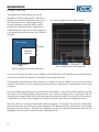
Purpose of this Document......................................................................................................................... 4
Rane Mongoose Documentation Set.................................................................................................... 5
System Requirements................................................................................................................................. 5
SECTION 2: UNDERSTANDING THE MONGOOSE SYSTEM....................................................... 6
The Big Picture............................................................................................................................................... 6
The Benefits of a Mongoose..................................................................................................................... 8
Components of a Mongoose System.................................................................................................... 9
The Mongoose Host Device...................................................................................................................... 10
Remote Audio Devices................................................................................................................................ 14
Mongoose Tracker Software..................................................................................................................... 16
Understanding how the Audio is Routed............................................................................................. 17
SECTION 3: DESIGNING YOUR SYSTEM.............................................................................................. 25
Tips and Recommendations..................................................................................................................... 25
Key Design Decisions to Make................................................................................................................ 26
Latency.............................................................................................................................................................. 28
Example Applications.................................................................................................................................. 29
RAD to RAD Using a Single Mongoose (Tie-Line).......................................................................... 29
RAD to DSP (or other device) via CobraNet using a Single Mongoose................................. 32
RAD to DSP (or other device) using Multiple Mongoose Devices........................................... 35
CobraNet Bundle to CobraNet Bundle................................................................................................. 41
SECTION 4: INSTALLATION AND CONFIGURATION ISSUES..................................................... 45
Key Installation Tasks and Recommended Work Flow.................................................................. 45
Installation Best Practices.......................................................................................................................... 46
Installing the Mongoose Off-site............................................................................................................. 46
Connecting the Mongoose to a Network – Best Practices.......................................................... 47
About the Control Network ...................................................................................................................... 47
About the CobraNet Network................................................................................................................... 48
Designing Each Network............................................................................................................................ 48
SECTION 5: INSTALLING AND USING THE MONGOOSE TRACKER...................................... 55
Installing Mongoose Tracker..................................................................................................................... 55
Starting Mongoose Tracker....................................................................................................................... 56
Working with Configuration Files............................................................................................................ 57
Configuration Issues to Note.................................................................................................................... 57
Distinguishing Between Live Device Settings Versus Configuration File Settings............ 58
Using the Configuration File During Installation............................................................................... 58
Creating the Configuration File................................................................................................................ 59
Generating RAD Labels.............................................................................................................................. 59
Updating (or Rolling Back) the Mongoose Firmware.................................................................... 61
Uninstalling Mongoose Tracker............................................................................................................... 62
INDEX.................................................................................................................................................................... 63
2
MONGOOSE
Design Manual
List of Figures
Figure 1: Audio system using analog cables............................................................................................................................................................. 6
Figure 2: Audio system using Mongoose and RADs............................................................................................................................................. 7
Figure 3: Front panel of the Mongoose....................................................................................................................................................................... 10
Figure 4: Rear panel of Mongoose ............................................................................................................................................................................... 12
Figure 5: Block diagram of Mongoose ....................................................................................................................................................................... 13
Figure 6: Purpose of each CAT 5 twisted pair........................................................................................................................................................... 14
Figure 7: Remote Audio Device..................................................................................................................................................................................... 15
Figure 8: Back of a RAD..................................................................................................................................................................................................... 16
Figure 9: Mongoose Tracker main window................................................................................................................................................................ 17
Figure 10: Simplified view of an audio routing matrix........................................................................................................................................... 18
Figure 11: Mongoose Tracker audio routing matrix............................................................................................................................................... 18
Figure 12: Hardware view of routing audio between two RADs that are connected to the same Mongoose............................... 19
Figure 13: Simple view and actual view of matrix routing signal from RAD to RAD on a single Mongoose.................................. 19
Figure 14: Hardware view of routing audio between two RADs that are connected to different Mongoose devices................ 20
Figure 15: Simple view and actual view of matrices routing signal from RAD to RAD on different Mongoose devices........... 21
Figure 16: Hardware view of routing audio between a RAD and a CobraNet device.............................................................................. 22
Figure 17: Simple view and actual view of matrix routing signal from RAD to CobraNet device........................................................ 22
Figure 18: Hardware view of routing aggregated RAD signals from different Mongoose devices to a CobraNet device........ 23
Figure 19: Matrices routing aggregated RAD signals from different Mongoose devices to a CobraNet device.......................... 24
Figure 20: CAD drawing - Mongoose front............................................................................................................................................................... 25
Figure 21: CAD drawing - Mongoose back............................................................................................................................................................... 25
Figure 22: CAD drawing - RAD1.................................................................................................................................................................................... 25
Figure 23: Maximum distance covered in CAT 5 scenario.................................................................................................................................. 27
Figure 24: Maximum distances covered using fiber optic cable....................................................................................................................... 27
Figure 25: One-line drawing for Saint Dawkins Church tie-line application................................................................................................ 29
Figure 26: Floor plan of Saint Dawkins Church tie-line application................................................................................................................. 30
Figure 27: Shop drawing for Saint Dawkins Church tie-line application....................................................................................................... 30
Figure 28: Configuration for Saint Dawkins Church tie-line application........................................................................................................ 31
Figure 29: One-line drawing for cafetorium example application.................................................................................................................... 32
Figure 30: Floor plan of cafetorium example application (illustrating RAD to DSP routing)................................................................ 33
Figure 31: Shop drawing for cafetorium example application (illustrating RAD to DSP routing)....................................................... 34
Figure 32: Configuration for Cafetorium (routing RADs from a single Mongoose to and from a CobraNet device).................. 34
Figure 33: One-line drawing for hotel example application................................................................................................................................ 36
Figure 34: Floor plan of hotel illustrating routing of RADs from multiple Mongoose devices to DSP equipment...................... 37
Figure 35: Shop drawing of hotel illustrating routing of RADs from multiple Mongoose devices to DSP equipment............... 38
Figure 36: Configuration for Mongoose A in hotel (RADs from multiple Mongoose devices to and from CobraNet)............... 39
Figure 37: Configuration for Mongoose B in hotel (RADs from multiple Mongoose devices to and from CobraNet)............... 40
Figure 38: One-line drawing for Kipling College music and paging system................................................................................................ 41
Figure 39: Floor plan for Kipling College music and paging system - illustrating Bundle aggregation............................................ 42
Figure 40: Shop drawing for Kipling College example application – illustrating Bundle aggregation.............................................. 43
Figure 41: Configuration for student union of Kipling College (two Mongoose devices into one CobraNet Bundle)............... 44
Figure 42: Configuration for cafeteria of Kipling College (two Mongoose devices into one CobraNet Bundle).......................... 44
Figure 43: Adjusting RAD to make it flush with wall.............................................................................................................................................. 46
Figure 44: Control Network - direct connection...................................................................................................................................................... 49
Figure 45: CobraNet Network - direct connection................................................................................................................................................. 49
Figure 46: Control Network - isolated for audio network.................................................................................................................................... 50
Figure 47: CobraNet Network - isolated for audio network................................................................................................................................ 51
Figure 48: Control Network - integrated with existing corporate network................................................................................................... 52
Figure 49: Control and CobraNet Networks - on same switch but isolated via VLAN............................................................................. 53
3
MONGOOSE
Design Manual
SECTION 1: INTRODUCTION
Perhaps you are familiar with the furry yet ferocious mongoose, a member of the Herpestidae family that
is known for its agility and cunning – so fast and smart that it can capture venomous snakes, even king
cobras. But did you know that a Rane Mongoose can perform a similar feat with your CobraNet network?
Now we’re certainly not insinuating that CobraNet is venomous! In fact, we’d say just the opposite.
CobraNet is an excellent technology for distributing digital audio. But its 8-channel Bundle architecture
can be difficult to utilize and tame, especially if you have only a few channels to distribute from within a
given space. If this describes your situation, you’ve come to the right place.
The Rane Mongoose system, designed to wrestle and control your CobraNet Bundles and other analog
cables, distributes digital audio signals over shielded CAT 5e cable between low channel count locations
and the rest of your audio system. To accomplish this, it utilizes a network of up to eight Remote Audio
Devices (or RADs) that are connected via CAT 5 cable to a single Mongoose host. A RAD, designed to
mount inside a standard US two or four gang switchbox, uses high value, professional quality technology to
transmit and receive up to four channels of digital audio – two channels in each direction. The Mongoose
to which these RADs are connected, serves as the host that controls and aggregates the channels and
connects them to the rest of the audio system.
Purpose of this Document
If you design audio systems and are planning to incorporate a Mongoose/RAD network into your next
design, then this design manual is for you. It is intended to help you through the design process by giving you
background information on the Mongoose system as well as the basic details of how CobraNet works (in
case you are unfamiliar with this digital networking technology). This manual details the benefits of using
a RAD network and illustrates how to effectively utilize these benefits in various audio applications. It also
includes suggested best practices, sample drawings and Mongoose configurations, and key information
you should provide to your installers.
PLEASE READ THIS: If you’re short on time and are tempted to jump right in without reading this
manual, we recommend that you at least skim "SECTION 3: DESIGNING YOUR SYSTEM" on page 25
and, most importantly, read about configuration files in "SECTION 5: INSTALLING AND USING THE
MONGOOSE TRACKER" on page 54. However, unless you need to get this design out the door in the next
hour, we strongly recommend that you review the entire manual. It contains valuable information that will
help ensure a smooth design and installation process.
4
MONGOOSE
Design Manual
Rane Mongoose Documentation Set
In addition to this design manual, the Rane documentation set includes an installation manual and a
software help system built into the Mongoose Tracker.
The Mongoose Installation Manual (available on the Rane website) explains the details of racking the
Mongoose and connecting it to the network, installing the RAD devices and connecting them to the
Mongoose, and troubleshooting any connection or audio problems that arise.
The software help system, embedded in the Mongoose Tracker software application, contains tutorial
simulations to introduce you to the software, information on Mongoose and RAD configuration, detailed
information about the user interface as well as detailed procedures for accomplishing specific tasks.
We also recommend you periodically check www.rane.com/mongoose at the Rane website for the latest
information on the system (for example, software updates, the release of new RAD models, line art, etc.).
System Requirements
To include a Mongoose/RAD network in an audio system, the system must meet the following requirements:
If you plan to use CobraNet to communicate between a Mongoose and other audio devices, those devices
must be CobraNet-enabled.
• You must have access to a computer running Microsoft Windows® XP (Service Pack 2 or higher)
or any version of Vista or Windows 7 (including 64-bit). The computer must also have an Ethernet
port, which you use to connect the computer to the Mongoose (either directly or via an Ethernet
network). This connection is necessary for using the Mongoose Tracker software to load configuration
information into the device and also for monitoring detailed status information. Note that some status
information is visible on the hardware itself.
• You must have administrative rights to install (or upgrade) the Mongoose Tracker software, but you
do not need administrative rights to run the software. Note that you also need administrative rights to
manually start or stop the RaneLink service (a Windows service installed with Mongoose Tracker that
runs at system boot up to ensure the establishment of communications between Mongoose Tracker
and the Mongoose). Manual control of this service is rarely needed.
• Most RADs require two, three, or four-gang standard switchboxes (for installation into a wall). The
switchbox must have a minimum depth of 2¼" (57 mm).
Windows is a registered trademark of Microsoft Corporation in the United States and other countries.
Mac and Mac OS are trademarks of Apple Inc., registered in the United States and other countries.
5
MONGOOSE
Design Manual
SECTION 2: UNDERSTANDING THE MONGOOSE SYSTEM
Rane understands the pain and expense of pulling and managing miles of analog cable throughout a large
audio installation, not to mention the potential for inferior sound quality. The advent and rapid adoption
of digital audio networking has almost ended this cabling and quality nightmare – but not quite. You
have probably utilized one or more of the networking solutions that exist today – for example, CobraNet,
Ethersound, and others. But, as discussed in the introduction, these solutions aren’t appropriate in all
situations. Because placing just a few channels on a large bandwidth network Bundle is inefficient and
expensive, you are probably still using analog cabling in low channel count applications.
Since you’re reading this manual, we can assume that you are seriously considering replacing all this
cabling with less expensive shielded CAT 5e cables and distributing the audio digitally via a RAD network.
Congratulations! You’ve made a wise choice. To help make this transition from analog to digital and from
older audio technology to new, this section provides a thorough explanation of the entire Mongoose
system – as well as suggestions for incorporating it into your larger audio system as efficiently as possible.
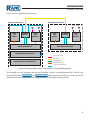
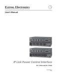
The Big Picture
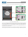
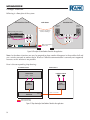
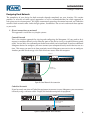
Before diving into the details, let’s take a look at the big picture. The following illustration shows an audio
system that uses analog cables to connect scattered channels to the rack room equipment
Control Room Rack
Auditorium
MIC CONDUIT
LINE CONDUIT
CobraNet® DSP
Mic 1
+6
1
+6
0
0
OFF
LOW
+6
4
6
0
10
2
OFF
MID
HIGH
OL
0
OFF
LOW
2
+6
0
8
LEVEL
+6
4
6
0
10
2
OFF
MID
HIGH
OL
0
OFF
LOW
3
+6
0
8
LEVEL
+6
4
6
0
10
2
OFF
MID
HIGH
OL
0
OFF
LOW
4
+6
0
8
LEVEL
EFFECTS
4
6
0
10
2
OFF
MID
HIGH
OL
OUTPUT
8
LEVEL
4
6
0
10
2
DRY
WET
OL
MLM 42S
MIC/LINE MIXER
8
LEVEL
POWER
CobraNet® Network
Meeting Room
DATA CONDUIT
CobraNet® Mic Mixer
MIC CONDUIT
LINE CONDUIT
CobraNet® DSP
:
Figure 1: Audio system using analog cables
6
MONGOOSE
Design Manual
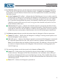
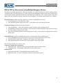
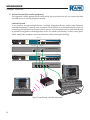
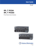
Now take a look at the difference when you replace the analog connections with a RAD network:
Control Room Rack
Auditorium
RAD4
RAD1
MICROPHONE
LINE OUTPUT
MICROPHONE
SIG / OL
POWER
LINE OUTPUT
SIG / OL
COMM
AUDIO RX
POWER
AUDIO TX
COMM
AUDIO RX
AUDIO TX
RAD4
RAD1
CobraNet® DSP
RAD4
RAD1
MICROPHONE
MICROPHONE
SIG / OL
POWER
LINE OUTPUT
LINE OUTPUT
SIG / OL
COMM
AUDIO RX
POWER
AUDIO TX
COMM
AUDIO RX
RAD1
+6
1
+6
0
0
OFF
LOW
+6
4
6
0
10
2
OFF
MID
HIGH
OL
0
OFF
LOW
2
+6
0
8
LEVEL
AUDIO TX
RAD4
+6
4
6
0
10
2
OFF
MID
HIGH
OL
0
OFF
LOW
3
+6
0
8
LEVEL
+6
4
6
0
10
2
OFF
MID
HIGH
OL
0
OFF
LOW
4
+6
0
8
LEVEL
EFFECTS
4
6
0
10
2
OFF
MID
HIGH
OL
OUTPUT
8
LEVEL
4
6
0
10
2
DRY
WET
OL
MLM 42S
MIC/LINE MIXER
8
LEVEL
POWER
DATA CONDUIT
CobraNet® Network
Meeting Room
RAD1
MICROPHONE
MICROPHONE
SIG / OL
POWER
SIG / OL
COMM
AUDIO RX
AUDIO TX
RAD1
RAD4
RAD1
LINE OUTPUT
DATA CONDUIT
REMOTE AUDIO DEVICES
1
1
2
2
1
2
1
2
3
1
2
1
2
4
1
2
1
2
5
1
2
1
2
6
1
2
1
2
7
1
2
1
2
8
1
2
1
2
COMM
LINE OUTPUT
AUDIO RX
AUDIO TX
RAD4
MICROPHONE
SIG / OL
SIG / OL
COMM
AUDIO RX
AUDIO TX
RAD1
ETHERNET
CobraNet®
1
POWER
MICROPHONE
POWER
RAD2
2
MONGOOSE
OVERLOAD
SIGNAL
IN USE / CONDUCTOR
ENABLED
LINK / ACTIVITY
IN
OUT
IN
OUT
IN
OUT
IN
OUT
IN
OUT
IN
OUT
IN
OUT
IN
OUT
PRIMARY
COMM
LOCATE
LINK
POWER
Remote Audio
CobraNet Interface
SECONDARY
MICROPHONE
SIG / OL
POWER
LINE INPUT
SIG / OL
COMM
AUDIO RX
AUDIO TX
RAD2
Figure 2: Audio system using Mongoose and RADs
As you can see, the Mongoose corrals and controls the low count channels in your audio system, aggregating
them so you can more efficiently utilize your CobraNet network. Each RAD input amplifies, digitizes, and
transmits the digital audio via CAT 5 to its host Mongoose, whereupon it can be routed to another RAD,
to a CobraNet Bundle, or both. Each output RAD receives via CAT 5 a digital signal and converts it to
analog for delivery to the attached device.
The specific details of the Mongoose and its associated RADs are explained in "Components of a Mongoose
System" on page 9, but you may first want to review the primary advantages to implementing this system.
7
MONGOOSE
Design Manual
The Benefits of a Mongoose
To most effectively design a system containing a RAD network, you need to understand its benefits so you
can take full advantage of them. For example, when using RADs, not only can you place line-level audio
and a microphone within the same conduit, you can place it on the same cable!
Following is a brief discussion of how key aspects of an audio system are handled within a Mongoose
system versus a typical analog system.
Less Expensive Cabling and Conduit
The foremost advantage of the Mongoose system is its use of CAT 5 cables for audio distribution. We don’t
have to tell you the cost benefits of using CAT 5 versus shielded audio cables and conduit. But bear with
us. Since we’re highlighting the benefits of a Mongoose, we’ll expound a bit more on the cost savings. Not
only is CAT 5 cable much less expensive than shielded analog cable, use of CAT 5 cable eliminates the
need for conduit. In addition to that, a RAD can transmit up to four channels (two input, two output) over
one CAT 5 cable. To top things off, the RAD is also able to transmit power and a data signal – all on that
same CAT 5 cable. To provide all this functionality in an analog world would require pulling six times the
amount of cabling needed by the RAD network as well as the use of conduit to house all that cabling! So
not only is the medium itself less expensive, but the difference in time and labor costs is huge. As a matter
of fact, by using CAT 5 cables, it may be possible for some economies of scale – why not have the IT folks
pull and terminate your CAT 5 cable at the same time they pull the data wires for the building?
Simpler Cable Termination
Your installers will be happy to know that they can toss their soldering irons aside. Terminating connections
in the Mongoose system involves nothing more than the simple process of crimping CAT 5 cables. And
unlike soldering, the crimping process does not require electricity.
An added benefit is the automatic testing that the Mongoose performs on each connection. When
the installer terminates and connects the CAT 5 cable to the RAD, the Mongoose automatically tests
the connection (assuming, of course, that the Mongoose is connected and powered on). The status of
the connection is immediately reported via the status lights on the RAD. If there’s a problem with the
connection, it can often be solved by simply re-crimping the cable – a much easier process than having to
re-solder a connection.
Better Sound Quality
Susceptibility to noise interference is much greater with analog than with digital transmission. Replacing
your analog channels with a RAD network immediately provides you with far superior sound quality –
especially if you’re transmitting the signal over substantial distances. In addition to eliminating noise
interference, the RAD’s transmitters and receivers have a high common mode range.
Digitizing the audio at the wall eliminates the mounting, expense, and trouble of isolation transformers
traditionally used in analog applications. Plus, passing low frequencies through analog isolation
transformers requires large cores and therefore more space. RADs save the space and pass those low
frequency Barry White vocal pronouncements to your application’s dual 18-inch subwoofers without
compromise.
8
MONGOOSE
Design Manual
Simpler and Faster to Change Audio Routing
In an analog system, audio is often routed by hardwiring the necessary connections. Therefore, to
change the routing, you must change the wiring – often a tedious and time-consuming process. With the
Mongoose system, however, the audio routing is handled by software. To change the routing, you simply
point and click within the Mongoose software application. Audio routing changes are literally as simple
as the click of a mouse.
Easier Troubleshooting
Have you or your installers ever been baffled by an audio connection that fails to work? You’ve pulled
all the cables, installed all the equipment, and, when you flip the switch, you hear silence instead of the
glorious sound you expected. You must then retrace your steps and try to locate the problem. In an analog
system, wiring mistakes and broken cables can be quite difficult to troubleshoot. The ends of the wires are
often hundreds of feet apart in completely different rooms. In a RAD network, the equipment contains
status indicators that immediately notify you if there’s a problem. For example, on a single RAD, a power
indicator tells you if a power signal is present, a communications indicator tells you if a data signal is
present, and an Audio Rx and an Audio Tx indicator tell you if an incoming or outgoing audio signal is
present. The Mongoose itself contains numerous status indicators as well. And the Mongoose Tracker
software, used primarily for configuring the system, provides even more troubleshooting information,
allowing you to troubleshoot your system from one location!
Components of a Mongoose System
A Mongoose system contains three primary components:
1. The host device (called the Mongoose) to which you can connect up to eight RADs. You can
then connect the Mongoose to your Ethernet network (for setup and control) and to additional
CobraNet-enabled audio equipment. The Mongoose is typically located in the audio rack room.
2. The RADs that serve as the input/output devices located in the rooms in which you want to send
or receive audio.
3. The Mongoose software (called the Mongoose Tracker), which you use to configure and troubleshoot
the system.
Another key player in a Mongoose system is the CobraNet network. Although there may be a few scenarios
in which CobraNet is not required (for example, sending audio from one RAD to another RAD on the same
Mongoose), in most applications you will want to take advantage of the power of CobraNet. Combining a
RAD and CobraNet network allows you to digitize and aggregate scattered channels and efficiently route
them to any location within the entire audio system.
9
MONGOOSE
Design Manual
The Mongoose Host Device
The primary purpose of the Mongoose host device is to connect up to eight RADs to a CobraNet network.
It is typically housed in the audio rack room along with the DSP and other audio equipment. In addition
to hosting the RADs, the Mongoose does the following:
•
•
•
•
•
Provides power to the connected RADs
Stores configuration settings for itself and for each of the connected RADs
Provides a connection to an Ethernet network (for control of the Mongoose and RADs)
Provides connections to both a primary and secondary (backup) CobraNet network
Displays various status indicators (LEDs) providing information about the health of the system
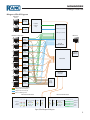
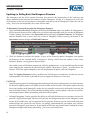
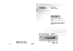
Front Panel Description
REMOTE AUDIO DEVICES
1
1
2
1
2
1
2
1
2
3
1
2
1
2
2
4
1
2
1
2
5
1
2
1
2
6
1
2
1
2
7
1
2
1
2
8
1
2
1
2
ETHERNET
RNET
CobraNet
raNett®
1
3 4
2
MONGOOSE
OVERLOAD
SIGNAL
IN USE / CONDUCTOR
COMM
LOCATE
ENABLED
LINK / ACTIVITY
LINK
POWER
IN
OUT
IN
OUT
IN
OUT
IN
OUT
IN
OUT
IN
OUT
IN
OUT
IN
OUT
PRIMARY
Remote Audio
CobraNet Interface
SECONDARY
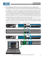
Figure 3: Front panel of the Mongoose
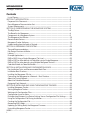
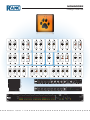
1 The Remote Audio Devices status indicators provide information about the RAD audio channels.
The numbers 1 through 8 at the top of the front panel correspond to the RAD ports 1 through 8
on the back of the Mongoose. For example, the status indicators for number 1 provide information
about the RAD connected on port 1.
Under each RAD number are four audio channels, two input and two output. These represent the
maximum number of channels a RAD is capable of transporting. However, not all RAD models use
all four channels. For example, the RAD1 model provides two microphone inputs, so for that model,
only the two columns of indicators labeled IN would be active.
There are three types of indicators:
� Overload LED (red) –indicates that the channel is experiencing a signal overload.
� Signal LED (green) – indicates the presence of an audio signal on this channel
� Enabled LED (yellow) – indicates the availability of the associated audio channel. If a RAD is
connected on this port and all Enabled lights are off, this indicates a problem with the CAT 5
connection or with the RAD. If the Enabled LEDs are flashing, this indicates that the physical
RAD model does not match the RAD model specified for this port in the Mongoose’s configuration.
10
MONGOOSE
Design Manual
2 The CobraNet status indicators provide information about the Mongoose’s CobraNet connection.
There are two sets of indicators for each CobraNet network – Primary and Secondary. Of course,
the secondary network indicators function only if you have implemented a secondary (or backup)
CobraNet network.
� In Use/Conductor LED (yellow) – indicates that the CobraNet port is in use, in other words CobraNet packets are being sent or received by the Mongoose. If the Mongoose has auto-negotiated
to be the CobraNet Conductor, this LED flashes (indicating it is both in use and is the Conductor). If you have connected both the primary and secondary CobraNet ports, only one of your
CobraNet networks will be active (or in use) at any given time, therefore, only one In Use/Conductor indicator will be active.
� Link/Activity LED (green) – indicates the CobraNet network is connected, and flashes if there
is activity on the network. If the Mongoose is connected to another CobraNet device or network
switch but the Link LED is off, this indicates a problem with the connection. If you have connected both the primary and secondary CobraNet ports, the Link LED for both ports should be on.
3 The Ethernet status indicators provide information about the Mongoose’s Ethernet connection.
� Comm LED (yellow) – flashes when the Mongoose is sending or receiving network packets to or
from the Mongoose Tracker software.
� Link LED (green) – indicates if the Ethernet network is connected. If the Mongoose is connected
to an Ethernet network but the Link LED is off, this indicates a problem with the connection.
Note: If an installation does not include an Ethernet network, this indicator is relevant only when
you connect a computer directly to the Mongoose. If the connection is working properly, the
Link LED lights up.
4 The remaining indicators on the front panel are the Locate and Power LEDs:
� Locate LED – flashes green when you place this device in Locate Mode (via the Mongoose
Tracker software). The purpose of this locate functionality is for verification, when working in
the software, of the physical device you are configuring or viewing. This is helpful when you are
working with multiple Mongoose devices. For more information about this functionality, see the
software help system.
� Power LED – indicates the Mongoose is powered on.
11
MONGOOSE
Design Manual
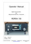
Rear Panel Description
1
MONGOOS
ONGOOSE
MADE
IN
U.S.A.
2 3
100-240 V
50/60 Hz 40 WATTS
5
ETHERNE
THERNET
THIS DEVICE COMPLIES WITH
PART 15 OF THE FCC RULES FOR
A CLASS 'B' COMPUTING DEVICE.
RANE
CORP.
4
REMOTE AUDIO DEVICES
1
LOCATE
LAN
POWER
LINK
6
PRIMARY
SECONDARY
IN USE /
CONDUCTOR
LINK /
ACTIVITY
2
3
4
5
6
7
7
8
ETHERNE
THERNET
REMOTE AUDIO DEVICES
8
AUDIO RX
PRIMARY
SECONDARY
1
2
3
4
5
6
7
8
AUDIO TX
COMM
POWER
ACN 001 345 482
Figure 4: Rear panel of Mongoose
1 Power IEC jack – connects to AC line voltage, 100-240 V, 50-60 Hz.
2 The Power and Locate LEDs on the back panel serve the same purpose as those on the front.
3 The Ethernet Link LED on the back panel serves the same purpose as the one on the front. The
Ethernet LAN LED flashes when the Mongoose detects any Ethernet packets on the network.
4 The CobraNet LEDs (In Use/Conductor and Link/Activity) on the back panel serve the same
purpose as those on the front.
5 The Remote Audio Devices LEDs on the back panel serve a different purpose from the ones on the
front. The front panel LEDs provide information about signal activity on each audio channel. The
back panel LEDs indicate the health of the CAT 5 connection between each RAD and the Mongoose.
Just as on the front panel, these LEDs are numbered 1 through 8 which correspond to the numbered
ports on the device. Each LED corresponds with one twisted pair within the CAT 5 cable. If the
twisted pair is functioning properly, the LED displays a solid green light.
� Audio Rx LED – lights solidly if the Mongoose’s receive pair is working properly.
� Audio Tx LED – lights solidly if the Mongoose’s transmit pair is working properly.
� Comm LED – lights solidly if the RAD’s data communications pair is working properly.
� Power LED – lights solidly if the Mongoose is supplying adequate power to the RAD port.
6 Ethernet port – used to connect the Mongoose to an Ethernet switch or directly to a computer.
Note that this Ethernet port contains auto-MDIX functionality, which means that if you connect
directly from this port to a computer, you can use either a standard Ethernet patch cable or a
crossover cable to make the connection. The auto-MDIX functionality takes care of coordinating the
proper connection between the devices.
7 CobraNet ports – used to connect the Mongoose to another CobraNet-enabled device or to a
network switch. Use the Primary port to connect your primary CobraNet network. If you have a
backup CobraNet network, connect the Mongoose to it using the Secondary port. Both ports have
the same Media Access Control (MAC) address. Note that the CobraNet ports do NOT contain
auto-MDIX functionality. Therefore, if you use this port to connect the Mongoose directly to another
CobraNet device, you MUST use a crossover cable.
8 Remote Audio Devices ports – used to connect each RAD to the Mongoose via a standard CAT 5
cable. You must use a standard Ethernet patch cable for this connection.
12
MONGOOSE
Design Manual
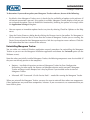
Mongoose Block Diagram
CobraNet
Primary
Ethernet
MAC/Phys
CobraNet
Hardware
Chip
Secondary
RX 2 Bundles, 16 Channels
Ethernet
MAC/Phys
TX 2 Bundles, 16 Channels
AES3 RX (x8), 16 Channels
Ethernet
Remote Audio Ports
1
Remote
Audio
Tranceivers
2
Remote
Audio
Tranceivers
3
Remote
Audio
Tranceivers
4
Remote
Audio
Tranceivers
5
Remote
Audio
Tranceivers
6
Remote
Audio
Tranceivers
7
Remote
Audio
Tranceivers
8
Remote
Audio
Tranceivers
AES3 TX (x8), 16 Channels
32 x 32
Audio Router
Ethernet
MAC/Phys
Controller
LED Display
Controller
Port
Power
Supply
Data communications (COMM)
2 digital audio channels (Rx)
2 digital audio channels (Tx)
Power: 24 VDC & ground
Rear Panel Indicators
Front Panel Indicators
Remote Audio Devices 1-8
2
1
1
2
Overload
Signal
Enabled
In
Out
CobraNet®
Primary Secondary
In Use /
Conductor
Link /
Activity
Ethernet
Ethernet
Comm
Locate
Locate
Lan
Power
Link
Power
Link
CobraNet®
Primary Secondary
In Use /
Conductor
Link /
Activity
Remote Audio Devices
1 2 3 4 5 6 7 8
Audio RX
Audio TX
Comm
Power
Figure 5: Block diagram of Mongoose
13
MONGOOSE
Design Manual
Remote Audio Devices
The primary purpose of a Remote Audio Device (RAD) is to amplify, digitize, and transmit a digital audio
signal via shielded CAT 5e cable to a Mongoose host device. RADs can also receive a digital signal from
the Mongoose and then convert it to analog before sending it to its attached audio equipment. RADs are
capable of transmitting and receiving up to four channels of digital audio (two in each direction). To better
fit your needs, however, Rane offers various RAD models. Some of these models handle a maximum of
two input or two output channels. Most RAD models are designed to fit in a standard U.S. two, three, or
four gang switchbox. For the most recent list of RAD models available, see www.rane.com/mongoose.
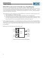
The CAT 5 cable that connects the RAD to the Mongoose also provides power to the RAD as well as a path
for data communications. This makes it possible to control the RAD’s configuration settings, view status
information, and update a RAD’s firmware – all from the host Mongoose. The following picture illustrates
how the four twisted pairs within the CAT 5 cable are utilized:
RAD NETWORK
CAT 5 CABLE
CONTENTS
Data communications (COMM)
2 digital audio channels (Rx)
2 digital audio channels (Tx)
Power: 24 VDC & ground
Figure 6: Purpose of each CAT 5 twisted pair
The orange pair is reserved for data communications between the RAD and the Mongoose. Data
communications is needed for such things as sending configuration information from the Mongoose to
the RAD, sending firmware updates from the Mongoose to the RAD, and sending status information from
the RAD to the Mongoose.
NOTE: Configuration information for a specific RAD (for example, LED intensity, microphone sensitivity,
and RAD and channel names) is stored in the Mongoose, not in the RAD. This makes it easy to swap in a
new RAD, if necessary, without losing configuration data.
The green pair carries two channels each of balanced, differential, digital audio. Rx refers to audio that the
RAD receives from the Mongoose.
The blue pair carries two channels each of balanced, differential, digital audio. Tx refers to audio that the
RAD sends to the Mongoose.
The brown pair provides 24 VDC power and ground for the RAD. This is obviously the wire you should
check if it appears a RAD is not receiving power.
14
MONGOOSE
Design Manual
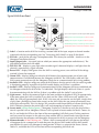
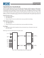
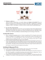
Typical RAD Front Panel
Custom Label Slot
Removable Locking Tab
Analog Audio Connection
SIG / OL green if an audio signal is detected, red light during signal overload.
POWER green when the RAD is receiving power, red if the voltage is low.
COMM green if the communications pair is detected, red if there is a problem.
1
2
3
4
5
6
MICROPHONE
MI
ICR
CROP
O H
MICROPHONE
OPHONE
SIG
SI / OL
O
SIG
G / OL
L
POWER
POWE
POWER
COMM
M
COMM
AU
UDIO RX
UD
UDI
RX
AUDIO
0
1
2
3
4
5
6
7
8
9
0
0
AU
UD
UDI
U
DIO TX
TX
AUDIO
RAD1
RA
RAD
AD1
1
9
8
7
Light sensor detects the light in the room and dims or brightens all LEDs appropriately.
AUDIO Tx green when the pair for transmitting audio is OK, red if there is a problem.
AUDIO Rx green when the pair for receiving audio is OK, red if there is a problem.
All four LEDs flashing green during Locate mode in Mongoose Tracker to verify location.
All four LEDs flashing red indicate a mismatch between the RAD and the configuration.
Figure 7: Remote Audio Device
Label – a location on the RAD for inserting a custom label of the input, output or channel number
associated with the corresponding jack. See "Generating RAD Labels" on page 58 for details.
XLR tab – push tab for releasing a microphone cable. This tab may be removed – details are in the
Mongoose Installation Manual.
Input/Output jacks – the actual jacks to which you connect the appropriate audio device(s). The
jacks differ based on the RAD model.
SIG/OL LED – displays a green light when an audio signal is detected, displays a red light when the
channel is experiencing a signal overload.
Power LED – displays solid green when the RAD is receiving power, turns solid red if the voltage
received is lower that expected.
Comm LED – displays solid green when the RAD detects the communication pair of wires and
communication is established between the Mongoose and RAD. The LED displays solid red if the
RAD cannot communicate with the Mongoose, likely due to a communication pair wiring problem.
Audio Rx LED – displays solid green when the RAD detects that the pair of wires for receiving audio
is functioning properly, regardless of the RAD model, displays red if there is a problem.
Audio Tx LED – displays solid green if communication with the Mongoose has been established and
the Mongoose informs the RAD of the Tx Audio lock. The light displays solid red, if there is a problem communicating with the RAD or if there is a problem with the Audio Tx pair of wires.
Light sensor – detects the amount of light in the room and dims or brightens all LEDs appropriately.
If the room where the RAD is installed is very dark and the “Allow LEDs to turn off ” option is enabled, the LEDs will go completely dark. If this is the case and you need to see the lights, simply shine
a light (from a flashlight or some other source) on the RAD. Note that you cannot permanently turn
these lights off manually. This is by design. We wanted to avoid the possibility of anyone thinking the
RAD is defective (because the power light is off ) and attempting to replace it unnecessarily.
Locate mode (all four flashing green) – Mongoose Tracker has a feature to verify the physical location of a specific RAD or Mongoose. When a RAD is placed in Locate mode, the Power, Comm, Audio Tx, and Audio Rx LEDs on the front of the corresponding RAD flash green. Flashing continues
until you cancel the request in the software, place another RAD in Locate mode, interrupt the connection between the computer and Mongoose, disconnect the RAD, or power cycle the Mongoose.
Mismatch mode (all four flashing red) – When a RAD is connected to a RAD port on the back of
a Mongoose device a comparison is made between the physical RAD model and the RAD model
specified for this port in the Mongoose’s configuration. If there is a mismatch the Power, Comm, 15
Audio Tx, and Audio Rx LEDs on the front of the corresponding RAD flash red.
MONGOOSE
Design Manual
Typical RAD Back Panel
2
– +
– +
1
1 RJ-45 (8P8C) jack for the CAT 5 cable.
Figure 8: Back of a RAD
2 Euroblock connectors to use if paralleling microphone jacks
(Disclaimer: As it is poor design to plug two microphones into a single microphone input, we do not
recommend this practice. If, however, you have a situation that warrants it, proceed with caution. We
recognize that paralleling microphone jacks can lower the cost of your audio system.)
NOTE: RADs are hot-swappable. In other words, you can replace a RAD without having to power down
the system. The Mongoose automatically detects the new RAD and configures it using the configuration
data stored in the Mongoose. If the configured RAD and the physical RAD do not match, the Mongoose
front panel Enabled LEDs for this RAD flash yellow. At the same time, the RAD’s Power, Comm, Audio
Rx and Audio Tx flash red during a mismatch.
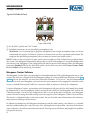
Mongoose Tracker Software
The Mongoose Tracker allows you to configure and troubleshoot the RADs and Mongoose devices in your
system. The software is shipped with the Mongoose product. It is also available free of charge on the Rane
website. To run the software, you must have Microsoft Windows® XP, Vista or 7 on your computer. To
communicate with your Mongoose, you must connect your computer to the appropriate network switch
or use a standard Ethernet patch cable (or a crossover cable) to connect it directly to a Mongoose.
Using the Mongoose Tracker, you configure each Mongoose RAD port with the RAD model that should
be connected to it. You also configure various settings for each RAD, for the Mongoose itself, and for the
CobraNet network. One of the key configuration tasks is to set up the audio routing for your Mongoose
system. You do this using the audio routing matrix that appears in the Mongoose Tracker’s main window.
This matrix is explained further in the next section. You can also find more information in the software’s
help system on working with the matrix.
In addition to configuring the Mongoose components and the audio routing, the software is a valuable
tool for troubleshooting any issues that may arise. Although you can determine a lot from the hardware
status indicators, the software provides more detail, allowing you to drill down and pinpoint the problem
with greater accuracy.
16
MONGOOSE
Design Manual
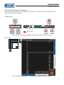
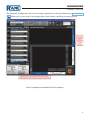
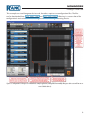
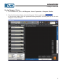
Following is an annotated screen shot of the Mongoose Tracker’s main window:
Figure 9: Mongoose Tracker main window
Understanding how the Audio is Routed
Understanding how the audio signal finds its way back and forth between a RAD and the host Mongoose
is fairly straightforward. It’s literally a direct connection. But where does it go from there and how do you
control it?
Depending on your audio system, there are several options for routing a RAD audio signal. You can send
the signal to one or more of the following:
• Another RAD connected to the same Mongoose
• Another RAD connected to a different Mongoose
• Another CobraNet-enabled device (for example, a DSP device)
17
MONGOOSE
Design Manual
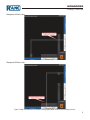
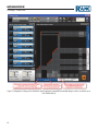
To configure the audio routing, you use the
Mongoose Tracker routing matrix. The matrix
contains an area for RAD channels and an area
for CobraNet channels, allowing the routing
of signals directly to and from RADs and/or
to and from CobraNet Bundles. Following is a
simplified picture of the matrix, illustrating how
it is separated into RAD channels and CobraNet
channels:
An actual configured matrix looks like this:
RAD channels
Output
CobraNet
channels
Input
Figure 10: Simplified view of an audio routing matrix
Figure 11: Mongoose Tracker audio routing matrix
As you can see, the matrix allows you to configure which RAD input and CobraNet receive audio channels
are routed to which RAD output and CobraNet transmit audio channels.
To thoroughly understand the matrix, however, it is helpful to see the hardware view of various routing
scenarios. The matrix can seem a bit abstract unless you have a solid picture in mind of what you’re trying
to achieve.
Each of the following routing scenarios includes four illustrations – two versions of the hardware view and
two versions of the corresponding software matrix view. The first hardware view is high level while the
second shows a more detailed view of the actual port connections involved. The first matrix illustration is
a simplified view of the routing configuration while the second shows the actual configured matrix.
Note the color key in each of the detailed hardware graphics. The orange lines represent the physical
connection between the RAD and its host Mongoose. The dotted red lines represent the virtual audio
connection between devices. The blue lines represent the physical CobraNet connections between the
Mongoose and the network switch and other CobraNet devices.
18
MONGOOSE
Design Manual
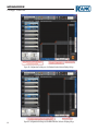
RAD to RAD routing (same Mongoose)
The following graphics illustrate a simple tie-line situation – routing audio between RADs that are
connected to the same Mongoose.
Hardware view:
RAD
MICROPHONE
MICROPHONE
SIG / OL
POWER
SIG / OL
COMM
AUDIO RX
AUDIO TX
RAD1
MONGOOSE
MADE
IN
U.S.A.
MONGOOSE
COMMERCIAL AUDIO
EQUIPMENT 24TJ
R
REMOTE AUDIO DEVICES
1
LOCATE
POWER
RANE
CORP.
100-240 V
50/60 Hz 40 WATTS
RAD
ETHERNET
THIS DEVICE COMPLIES WITH
PART 15 OF THE FCC RULES FOR
A CLASS 'B' COMPUTING DEVICE.
LAN
LINK
SECONDARY
PRIMARY
IN USE /
CONDUCTOR
LINK /
ACTIVITY
3
4
5
6
7
ETHERNET
REMOTE AUDIO DEVICES
8
AUDIO RX
PRIMARY
1
SECONDARY
2
3
4
5
6
7
8
AUDIO TX
COMM
POWER
ACN 001 345 482
RAD network (CAT 5)
Audio routing (virtual)
RAD
2
LINE OUTPUT
POWER
COMM
LINE OUTPUT
AUDIO RX
AUDIO TX
LINE OUTPUT
POWER
COMM
RAD4
LINE OUTPUT
AUDIO RX
AUDIO TX
RAD4
Figure 12: Hardware view of routing audio between two RADs that are connected to the same Mongoose
Matrix view:
R
R
R
Figure 13: Simple view and actual view of matrix routing signal from RAD to RAD on a single Mongoose
19
MONGOOSE
Design Manual
RAD to RAD routing (different Mongoose)
The following graphics illustrate audio routing between RADs connected to different Mongoose devices.
Hardware view:
RAD
MICROPHONE
MICROPHONE
SIG / OL
POWER
SIG / OL
COMM
AUDIO RX
AUDIO TX
RAD1
MONGOOSE A
MONGOOSE
MADE
IN
U.S.A.
MONGOOSE A
COMMERCIAL AUDIO
EQUIPMENT 24TJ
RANE
CORP.
ETHERNET
THIS DEVICE COMPLIES WITH
PART 15 OF THE FCC RULES FOR
A CLASS 'B' COMPUTING DEVICE.
LAN
POWER
LINK
2
3
4
5
6
7
ETHERNET
REMOTE AUDIO DEVICES
8
PRIMARY
SECONDARY
IN USE /
CONDUCTOR
PRIMARY
AUDIO RX
SECONDARY
1
2
3
4
5
6
7
8
AUDIO TX
COMM
LINK /
ACTIVITY
R
100-240 V
50/60 Hz 40 WATTS
REMOTE AUDIO DEVICES
1
LOCATE
POWER
ACN 001 345 482
Tx 425
COBRANET NETWORK
ETHERNET SWITCH
COBRANET DSP
MONGOOSE B
MONGOOSE
MADE
IN
U.S.A.
MONGOOSE B
COMMERCIAL AUDIO
EQUIPMENT 24TJ
R
100-240 V
50/60 Hz 40 WATTS
REMOTE AUDIO DEVICES
1
LOCATE
POWER
RANE
CORP.
Rx 425
ETHERNET
THIS DEVICE COMPLIES WITH
PART 15 OF THE FCC RULES FOR
A CLASS 'B' COMPUTING DEVICE.
LAN
LINK
2
3
4
5
6
PRIMARY
SECONDARY
IN USE /
CONDUCTOR
7
ETHERNET
REMOTE AUDIO DEVICES
8
AUDIO RX
PRIMARY
SECONDARY
1
2
3
4
5
AUDIO TX
COMM
LINK /
ACTIVITY
POWER
ACN 001 345 482
RAD network (CAT 5)
RAD
CobraNet network (CAT 5)
LINE OUTPUT
POWER
COMM
LINE OUTPUT
AUDIO RX
AUDIO TX
RAD4
Audio routing (virtual)
Figure 14: Hardware view of routing audio between two RADs that are connected to different Mongoose devices
Simplified Matrix view:
MONGOOSE B
R
MONGOOSE A
CobraNet Bundle 425
R
20
6
7
8
MONGOOSE
Design Manual
Mongoose A Matrix view:
Mongoose B Matrix view:
Figure 15: Simple view and actual view of matrices routing signal from RAD to RAD on different Mongoose devices
21
MONGOOSE
Design Manual
RAD to CobraNet device
The following graphics illustrate the routing of audio between a RAD channel and a CobraNet device.
Hardware view:
RAD
MICROPHONE
MICROPHONE
SIG / OL
POWER
SIG / OL
COMM
AUDIO RX
AUDIO TX
RAD1
MONGOOSE
MADE
IN
U.S.A.
MONGOOSE
Tx 425
COMMERCIAL AUDIO
EQUIPMENT 24TJ
RANE
CORP.
ETHERNET
THIS DEVICE COMPLIES WITH
PART 15 OF THE FCC RULES FOR
A CLASS 'B' COMPUTING DEVICE.
REMOTE AUDIO DEVICES
1
LOCATE
LAN
POWER
LINK
PRIMARY
SECONDARY
IN USE /
CONDUCTOR
LINK /
ACTIVITY
R
100-240 V
50/60 Hz 40 WATTS
2
3
4
5
6
7
ETHERNET
REMOTE AUDIO DEVICES
8
AUDIO RX
PRIMARY
SECONDARY
1
2
3
4
5
6
7
8
AUDIO TX
COMM
POWER
ACN 001 345 482
Tx 425
RAD network (CAT 5)
COBRANET NETWORK
ETHERNET SWITCH
Cobranet network
Audio routing (virtual)
Rx 425
ETHERNET
ANY COBRANET DEVICE
Rx 425
ANY COBRANET DEVICE
Figure 16: Hardware view of routing audio between a RAD and a CobraNet device
Matrix view:
CobraNet Bundle 425
Any
CobraNet
Device
Rx 425
R
Figure 17: Simple view and actual view of matrix routing signal from RAD to CobraNet device
22
MONGOOSE
Design Manual
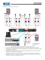
RADs from multiple Mongoose devices to a CobraNet device
The following graphics illustrate the aggregation of RAD channels from two Mongoose devices into a
single CobraNet Bundle. These graphics are more complex than the previous ones, so we’ll add more
explanation.
In this scenario, one Mongoose transmits two RAD channels to another Mongoose via CobraNet. The
second Mongoose combines two additional RAD channels (which are connected directly to the device)
with the two RAD channels arriving from the first Mongoose (via CobraNet). These four RAD channels
are then transmitted from the second Mongoose via a single CobraNet Bundle.
The high level signal flow view is self-explanatory. That is not the case with the detailed hardware view,
however. The following procedure explains the numbered steps you see in the illustration:
1. Mongoose A receives the signal from four RAD channels.
2. Mongoose A transmits all four channels via CobraNet Bundle 300 (Tx 300).
3. Mongoose B receives CobraNet Bundle 300 (Rx 300).
4. Mongoose B receives the signal from four RAD channels.
5. Mongoose B transmits all eight RAD channels via CobraNet Bundle 301 (Tx 301).
6. Another CobraNet device receives all eight RAD channels via CobraNet Bundle 301 (Rx 301).
Hardware view:
RAD
RAD network (CAT 5)
RAD
Cobranet network
MICROPHONE
MICROPHONE
SIG / OL
POWER
AUDIO RX
MONGOOSE A
Tx 300
ETHERNET
THIS DEVICE COMPLIES WITH
PART 15 OF THE FCC RULES FOR
A CLASS 'B' COMPUTING DEVICE.
COMMERCIAL AUDIO
EQUIPMENT 24TJ
LAN
POWER
RANE
CORP.
LINK
2
3
4
5
6
7
ETHERNET
PRIMARY
SECONDARY
IN USE /
CONDUCTOR
e containing 8 RAD cha
Bundl
nnel
s
AUDIO TX
RAD1
SECONDARY
1
2
3
4
5
6
7
8
AUDIO TX
COMM
POWER
ACN 001 345 482
Tx 300
2
COBRANET NETWORK
ETHERNET SWITCH
5
Bundle 301 contains
eight RAD channels:
four from Mongoose A
and four from Mongoose B.
RAD
MONGOOSE
MADE
IN
U.S.A.
ETHERNET
THIS DEVICE COMPLIES WITH
PART 15 OF THE FCC RULES FOR
A CLASS 'B' COMPUTING DEVICE.
COMMERCIAL AUDIO
EQUIPMENT 24TJ
POWER
RANE
CORP.
R
100-240 V
50/60 Hz 40 WATTS
LAN
LINK
PRIMARY
SECONDARY
IN USE /
CONDUCTOR
LINK /
ACTIVITY
2
3
4
5
6
7
MICROPHONE
SIG / OL
MICROPHONE
SIG / OL
COMM
AUDIO RX
MICROPHONE
SIG / OL
AUDIO TX
POWER
SIG / OL
COMM
AUDIO RX
RAD1
REMOTE AUDIO DEVICES
1
LOCATE
MICROPHONE
POWER
6
MONGOOSE B
MONGOOSE B
Rx 300 Tx 301
AUDIO RX
REMOTE AUDIO DEVICES
PRIMARY
AUDIO RX
Bundle 300 contains
four RAD channels.
RAD
SIG / OL
COMM
8
LINK /
ACTIVITY
R
100-240 V
50/60 Hz 40 WATTS
REMOTE AUDIO DEVICES
1
LOCATE
POWER
1
MONGOOSE A
MONGOOSE
MICROPHONE
SIG / OL
AUDIO TX
RAD1
Audio routing (virtual)
MADE
IN
U.S.A.
MICROPHONE
SIG / OL
COMM
Rx 300
Tx 301
3
AUDIO TX
RAD1
4
ETHERNET
REMOTE AUDIO DEVICES
8
AUDIO RX
PRIMARY
SECONDARY
1
2
3
4
5
6
7
8
AUDIO TX
COMM
POWER
ACN 001 345 482
Rx 301
ANY COBRANET DEVICE
Rx 301
ETHERNET
ANY COBRANET DEVICE
Figure 18: Hardware view of routing aggregated RAD signals from different Mongoose devices to a CobraNet device
23
MONGOOSE
Design Manual
Simplified Matrix view:
Mongoose A Matrix view:
MONGOOSE B
CobraNet
Bundle 301
Any
CobraNet
Device
Rx 301
MONGOOSE A
R
R
CobraNet Bundle 300
R
R
Note: In the above illustration, each line represents
two channels.
Mongoose B Matrix view:
Figure 19: Simple view and actual view of matrices routing aggregated RAD signals from different Mongoose devices to a CobraNet device
24
MONGOOSE
Design Manual
SECTION 3: DESIGNING YOUR SYSTEM
Now that you have reviewed the basics, you are ready to begin designing this technology into an audio
system. The purpose of this chapter is to provide tips and suggestions for incorporating RADs and
Mongoose devices into your design. Also included are some sample applications and representative oneline drawings. Our hope is that one of these comes close enough to your situation that you’ll have a head
start with your own design. After completing this section, you should be well-equipped to create your
design documents and construction documents. We’ll start with a list of specific recommendations.
Tips and Recommendations
1. In your system diagrams, use the Mongoose CAD drawings provided by Rane.
Rane provides CAD drawings of the Mongoose hardware (line art of the front and rear panels and
shop drawings of a RAD and a Mongoose) for you to use in your drawings. The files are in the .dwg
format, a format for AutoCAD. You can get these files from the Rane website, and on the CD that
comes with the Mongoose. Also on the website and CD are more detailed color pictures of the
hardware in a .jpg format. Following are examples of the CAD drawings:
REMOTE AUDIO DEVICES
1
1
2
2
1
2
1
2
3
1
2
1
2
4
1
2
1
2
5
1
2
1
2
6
1
2
1
2
7
1
2
1
2
8
1
2
1
2
ETHERNET
CobraNet®
1
2
MONGOOSE
OVERLOAD
SIGNAL
IN USE / CONDUCTOR
ENABLED
LINK / ACTIVITY
IN
OUT
IN
OUT
IN
OUT
IN
OUT
IN
OUT
IN
OUT
IN
OUT
IN
OUT
PRIMARY
COMM
LOCATE
LINK
POWER
Remote Audio
CobraNet Interface
SECONDARY
Figure 20: CAD drawing - Mongoose front
MONGOOSE
MADE
IN
U.S.A.
ETHERNET
THIS DEVICE COMPLIES WITH
PART 15 OF THE FCC RULES FOR
A CLASS 'B' COMPUTING DEVICE.
POWER
RANE
CORP.
100-240 V
50/60 Hz 40 WATTS
REMOTE AUDIO DEVICES
1
LOCATE
LAN
LINK
2
3
4
5
6
7
PRIMARY
SECONDARY
IN USE /
CONDUCTOR
ETHERNET
REMOTE AUDIO DEVICES
8
PRIMARY
AUDIO RX
SECONDARY
1
2
3
4
5
6
7
8
AUDIO TX
COMM
LINK /
ACTIVITY
POWER
ACN 001 345 482
Figure 21: CAD drawing - Mongoose back
MICROPHONE
SIG / OL
POWER
MICROPHONE
SIG / OL
COMM
AUDIO RX
AUDIO TX
RAD1
Figure 22: CAD drawing - RAD1
2. Create the Mongoose configuration file during the design phase and provide this file to your
installer.
We strongly recommend that you create a configuration file during the design process. You do not
need any Mongoose hardware to create this file. All you need is the Mongoose Tracker software
and a computer running Microsoft Windows® (see "System Requirements" on page 5). Providing
this configuration file to your installers increases the efficiency and accuracy of their work. Simply
include this file along with the other drawings and documentation that you give to your installers.
See "Working with Configuration Files" on page 56 for more details.
25
MONGOOSE
Design Manual
3. Be sure to design the routing of the CobraNet Bundles for your entire system during your
planning. You’ll appreciate this when it is time to configure the Mongoose audio routing matrix!
4. For large audio systems, consider using CobraCAD software to help with your network design.
CobraCAD is a software application that provides a simple graphical user interface for visualizing
and designing CobraNet networks. Because it provides on screen visualization of the audio,
Ethernet, and virtual Bundle connections throughout the entire network, it can be very helpful
when designing large, complex systems. With CobraCAD, you can dynamically build a system on
screen and perform design rule checking to catch errors. Note that CobraCAD is no longer actively
supported, and therefore, does not contain Mongoose and RAD devices. It is still useful, however,
for learning about CobraNet and for visualizing and planning a CobraNet network.
Key Design Decisions to Make
Following are a list of questions to consider when creating your Mongoose design.
1. Does the audio system you’re designing actually need the Mongoose technology?
If you read the introduction to this manual (or listened carefully to the Mongoose sales pitch), you
understand the benefits of using a Mongoose system. Deciding which situations warrant its use
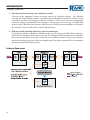
is the trickier part. If your system contains any of the following characteristics, it’s likely that the
Mongoose would be beneficial.
• The system needs to transmit and receive a small number of audio channels between a rack
room and multiple, scattered locations.
• The system requires digital transmission of the audio signal. This could be due to distance
issues or simply the need for higher quality sound.
• The total number of wall connections in the entire system is high. (Installing and testing a large
number of analog wall connections requires a tremendous amount of labor.)
The example applications in this manual (see "Example Applications" on page 29) further illustrate
when and how to add Mongoose technology to an audio system. These examples also illustrate the
conversion of generic one-line drawings to detailed drawings containing a Mongoose and RADs.
2. What are the maximum distances you’ll need to accommodate between a RAD and its host
Mongoose and between a Mongoose and the network switch or other audio equipment?
The maximum distance allowed between a RAD and a Mongoose is 150 meters. If you need to
accommodate larger distances, you may need to include multiple Mongoose devices in your
installation, guaranteeing that there is a Mongoose within 150 meters of each RAD.
In addition to this distance restriction between RADs and Mongoose devices, there is also the
standard Ethernet distance restriction of 100 meters (if using CAT 5 cables) between the Mongoose
and any other audio device (including another Mongoose) or network switch. If you need to
accommodate a distance larger than 100 meters and are unable to use additional network switches,
you could use fiber optic cable instead of CAT 5. If you choose to use multiple network switches,
The maximum hops allowed in a CobraNet network (depending on the acceptable latency) is 6.
26
MONGOOSE
Design Manual
This graphic shows a CAT 5 scenario involving two
Mongoose devices. In this situation, the maximum
distance between the RADs would be 500 meters.
The next graphic shows a scenario that uses both
CAT 5 and fiber to connect RADs located in
different buildings more than 100 meters apart.
FIBER OPTIC
Single mode = very far
Multi mode = 2,000 meters
BUILDING A
RAD
MEDIA CONVERTER
RAD CAT 5
150 meters
CobraNet CAT 5
100 meters
BUILDING B
ETHERNET SWITCH
CobraNet CAT 5
100 meters
MONGOOSE A
MONGOOSE
CobraNet CAT 5
100 meters
RAD CAT 5
150 meters
ETHERNET SWITCH
CobraNet CAT 5
100 meters
RAD
CobraNet CAT 5
100 meters
MONGOOSE
RAD CAT 5
150 meters
MONGOOSE B
RAD CAT 5
150 meters
RAD
COBRANET
NETWORK
RAD
RAD network (CAT 5)
Cobranet network (CAT 5)
Fiber Optic cable
Figure 23: Maximum distance covered in CAT 5 scenario
Figure 24: Maximum distances covered using fiber optic cable
3. How many Mongoose devices do you need?
Each Mongoose accommodates eight RADs. Therefore, deciding how many Mongoose devices
you need requires just a little simple math. If distance is an issue, however, you may want to add
additional Mongoose devices that you can place close to the RADs. See the previous question for
more details about distance issues.
4. What network design is appropriate for your situation?
When making networking decisions for the Mongoose system, you must think in terms of two
different networks – the control network and the CobraNet network. The control network, which
you connect to via the Mongoose Ethernet port, manages the communication between your
computer and the Mongoose. You use this network for configuring and monitoring the Mongoose
system. The CobraNet network, which you connect to via the Mongoose CobraNet port, manages
the transmission of the digital audio signals. Depending on your situation, there are various ways
to design these two networks. Unless your system is particularly large and complex, your network
design should be fairly straightforward. There are enough issues to consider, however, that we have
dedicated an entire section to this topic. See "Designing Each Network" on page 49.
27
MONGOOSE
Design Manual
5. How do you plan to manage your CobraNet network?
You can use the Mongoose Tracker to manage several key CobraNet settings – the CobraNet
transmit and receive Bundle numbers associated with the Mongoose host device, and the routing
of audio to and from the Mongoose CobraNet Bundles. If you want to view and manage other
CobraNet settings not included in the Mongoose Tracker, you can do so using an SNMP MIB
browser or the CobraNet Disco software. Note that to use SNMP, you must configure an IP address
for CobraNet. You can do this from within CobraNet Disco.
6. Will you include a backup CobraNet system in your design?
If you plan to include a redundant CobraNet system in your design to handle failover situations,
you’re in luck. Mongoose makes this easy for you. The Mongoose hardware contains two CobraNet
ports, one for your primary network and one for your secondary network. Connect the secondary
port to your backup system and, voila, you’re good to go. If the primary network fails, the secondary
network automatically becomes active.
Latency Awareness
28
MONGOOSE
Design Manual
Example Applications
This section includes several example audio designs utilizing the Mongoose system. Each example includes
a generic one-line audio design, a detailed floor plan incorporating the Mongoose technology, and a shop
drawing (similar to the one-line drawing but with Mongoose equipment specified). Each example also
includes a link to its corresponding Mongoose Tracker configuration file (on the Rane website). You must
use the Mongoose Tracker application to open and view these configuration files.
We’ll begin with the simplest design – a tie-line.
RAD to RAD Using a Single Mongoose (Tie-Line)
This example involves the Saint Dawkins Church, which has a congregation of about 2000 people. The main
sanctuary of the church holds 1300 people, so there is occasionally an overflow problem. It happens rarely,
however, so the church board has decided against the expensive proposition of enlarging the sanctuary.
Instead, they want to use the large meeting room in the church school building across the street to house
overflow congregation members. They plan to install a projection system that will transmit the audio from
the sanctuary to this meeting room.
Mongoose technology is perfect for this situation. Since the meeting room is across the street from the
church (and the source of the audio signal), installing analog cables could prove problematic. Even with
the addition of isolation transformers, there is absolutely no guarantee that the sound quality will be
suitable. The church board would definitely be hearing a few complaints from members who had to sit in
a room across the street and couldn’t understand a thing that was said! The digital signal provided by the
Mongoose system solves this issue completely, delivering clear sound to the poor folks who slept too late
to get a church seat. Also, because it’s a simple tie-line system, the Mongoose provides the connection
without requiring a CobraNet network. The signal travels directly from an input RAD to the Mongoose to
an output RAD in the overflow room.
Following is the one-line drawing for this audio system:
St. Dawkins
Existing
Church
Mixer
Overflow
Long distance
to Overflow Hall
across street
Left
Powered
Speaker
Right
Powered
Speaker
Figure 25: One-line drawing for Saint Dawkins Church tie-line application
29
MONGOOSE
Design Manual
Following is a floor plan of the system:
Saint Dawkins Church
79th Street
Overflow Hall
powered
speaker
powered
speaker
assumes <150 meters
between buildings
Existing analog audio system
LINE INPUT
LINE INPUT
SIG / OL
POWER
LINE OUTPUT
AUDIO RX
AUDIO TX
POWER
MONGOOSE
R
100-240 V
50/60 Hz 40 WATTS
ETHERNET
THIS DEVICE COMPLIES WITH
PART 15 OF THE FCC RULES FOR
A CLASS 'B' COMPUTING DEVICE.
COMMERCIAL AUDIO
EQUIPMENT 24TJ
RANE
CORP.
REMOTE AUDIO DEVICES
1
LOCATE
LAN
POWER
LINK
PRIMARY
SECONDARY
IN USE /
CONDUCTOR
LINK /
ACTIVITY
2
3
4
5
6
7
ETHERNET
REMOTE AUDIO DEVICES
PRIMARY
1
SECONDARY
2
AUDIO RX
AUDIO TX
RAD network (CAT 5)
Audio cable
8
AUDIO RX
COMM
RAD4
RAD3
MADE
IN
U.S.A.
LINE OUTPUT
SIG / OL
COMM
3
4
5
6
7
8
AUDIO TX
COMM
POWER
ACN 001 345 482
Figure 26: Floor plan of Saint Dawkins Church tie-line application
Note: In the above situation, you may be tempted to place another Mongoose in the overflow hall and
use a wireless network to connect them. Wireless CobraNet communication is currently not supported,
however, so this solution is not possible.
Here is the corresponding shop drawing:
OVERFLOW HALL
ST. DAWKINS CHURCH
CHURCH MIXER
AUX 3
POWERED SPEAKERS
AUX 4
RAD4
LINE OUTPUTS
RAD3
LINE INPUTS
PORT 1
MONGOOSE
CAT 5 = 120 meters
PORT 2
RAD network (CAT 5)
Balanced Audio (XLR)
Figure 27: Shop drawing for Saint Dawkins Church tie-line application
30
MONGOOSE
Design Manual
The Mongoose configuration file for this example application can be downloaded here: saint_dawkins.
mgs. Following is a screen shot of the configuration’s main window, including the routing matrix:
Figure 28: Configuration for Saint Dawkins Church tie-line application
31
MONGOOSE
Design Manual
RAD to DSP (or other device) via CobraNet using a Single Mongoose
Since we can safely assume that you’ve been inside an elementary school at some point in your life, we
can also assume that you are familiar with those funny room combinations called “cafetoriums” – a lunch
room and auditorium rolled into one. The following sample application illustrates a possible Mongoose
system that would serve such a space.
This cafetorium is used for school plays and other performances and functions. Audio requirements are:
• Four microphones are needed on the stage.
• Two powered speakers will be mounted high on the wall on either side of the stage.
• The school also wants the capability to make announcements from the opposite side of the room
and to play background music (during lunch or prior to the beginning of a performance). They
want to control this music from the back of the room, not from the stage area.
In this example, the Mongoose is a wise choice because it provides the school with tremendous flexibility
and extensibility. While delivering superb sound quality in the cafetorium, it also ties in with the existing
school paging system, and provides the possibility of additional functionality in the future (as new RADs
are introduced).
Following is the one-line drawing for this audio system:
Mics
on
Stage
Back
of
Room
AutoMixer
Line
Input
Left
Powered
Speaker
Right
Powered
Speaker
Figure 29: One-line drawing for cafetorium example application
32
MONGOOSE
Design Manual
Following is the floor plan for the system:
powered
speaker
powered
speaker
RAD4 mounted
high on wall,
near powered
speaker, stage left
Stage Left
LINE OUTPUT
Mic 1
Mic 2
MICROPHONE
LINE OUTPUT
COMM
AUDIO RX
AUDIO TX
POWER
Mic 3
MICROPHONE
SIG / OL
POWER
RAD4 mounted
high on wall,
near powered
speaker, stage right
RAD1s for stage
mics mounted
on sides or
back of stage
MICROPHONE
SIG / OL
COMM
AUDIO RX
Mic 4
SIG / OL
AUDIO TX
POWER
MONGOOSE
MADE
IN
U.S.A.
COMMERCIAL AUDIO
EQUIPMENT 24TJ
RANE
CORP.
ETHERNET
THIS DEVICE COMPLIES WITH
PART 15 OF THE FCC RULES FOR
A CLASS 'B' COMPUTING DEVICE.
LAN
POWER
LINK
LINK /
ACTIVITY
R
100-240 V
50/60 Hz 40 WATTS
PRIMARY
SECONDARY
IN USE /
CONDUCTOR
AUDIO RX
LINE OUTPUT
POWER
AUDIO TX
LINE OUTPUT
COMM
AUDIO RX
RAD1
REMOTE AUDIO DEVICES
1
LOCATE
MICROPHONE
SIG / OL
COMM
RAD1
RAD4
Stage Right
2
3
4
5
6
7
AUDIO TX
RAD4
ETHERNET
REMOTE AUDIO DEVICES
8
AUDIO RX
PRIMARY
1
SECONDARY
2
3
4
5
6
7
8
AUDIO TX
COMM
POWER
ACN 001 345 482
Rx 395
Tx 486
Mic 5
Music Input
MICROPHONE
LINE INPUT
Computer is only required for system setup.
MP3
player
MENU
SIG / OL
Ethernet Switch
POWER
SIG / OL
COMM
AUDIO RX
AUDIO TX
RAD2
Rx 486
CobraNet Auto-Mixer DSP
Tx 395
CobraNet®
RAD2 on low rear wall
for announcements,
music, projection, etc.
RAD network (CAT 5)
Cobranet network (CAT 5)
Ethernet (CAT 5)
Audio cable
Figure 30: Floor plan of cafetorium example application (illustrating RAD to DSP routing)
• Two RAD1s are installed on the front of the stage. These accommodate the 4 required mics.
• Two RAD4s are installed high on the wall near the speakers. Two to four powered speakers could
be plugged into these RADs.
• One RAD2 is installed to satisfy the requirement for a microphone and line input (for playing
background music) at the back of the room,
• This application contains a total of five RADs, therefore only one Mongoose is needed. The
Mongoose is housed in a sound equipment room along with a network switch and a CobraNet
DSP box that contains a microphone auto-mixer.
33
MONGOOSE
Design Manual
Here is the corresponding shop drawing:
RAD1
MIC
INPUTS
Stage
Back
RAD1
MIC
INPUTS
Stage Left
Powered
RAD4
LINE
OUTPUTS
RAD2
MIC / LINE
INPUTS
Stage Right
MONGOOSE
RAD4
LINE
OUTPUTS
Powered
Rx 395
Tx 486
ETHERNET SWITCH
Rx 486
Tx 395
RAD network (CAT 5)
Cobranet network (CAT 5)
Audio cable (XLR)
COBRANET AUTO-MIXER
Figure 31: Shop drawing for cafetorium example application (illustrating RAD to DSP routing)
The Mongoose configuration file for this example application can be downloaded here: cafetorium.mgs.
Following is a screen shot of the configuration’s main window, including the routing matrix:
34
Figure 32: Configuration for Cafetorium example application (routing RADs from a single Mongoose to and from a CobraNet device)
MONGOOSE
Design Manual
RAD to DSP (or other device) using Multiple Mongoose Devices
The following sample application is a bit more complex. It is a hotel that contains several meeting rooms,
a ballroom, and a restaurant/bar. It is a prime target for the Mongoose because of the low channel count
in each room and the scattered locations of each audio input and output. This system requires more than
eight RADs and, therefore, requires more than one Mongoose. The specific requirements are as follows:
Meerkat Room (used for meetings, conference sessions, roundtable discussions)
• Six microphones on one side of the room
• Four powered speakers high on the wall – on the sides and in the back of the room
Cusimance Room (used mostly for presentations)
• Two microphones – one in the northwest corner and one in the southeast corner
• Amplification of audio from a computer. This computer could be located in the northwest corner
or in the southeast corner of the room.
• Two to four powered speakers mounted high on the wall – in the southwest and northeast corners
of the room
Atilax Ballroom (used for roundtable discussions, presentations, music performances)
• Seven microphones to be placed on the west, north, and/or south sides of the room
• Amplification of audio from a computer, DVD player, or similar device
• Four powered speakers on the north, south, and east sides of the room.
Hotel Restaurant that also contains a bar
Carnivore Cantina (the restaurant)
• Connection for a satellite music service to the hotel’s central audio system
• Connection for a CD jukebox to the hotel’s central audio system
Botswana Bar
• Connection for cable TV to the hotel’s central audio system
• Connection for a TV with DVD player to hotel’s central audio system
35
MONGOOSE
Design Manual
Following is the one-line drawing for this audio system:
Bar Inputs
Atilax Room Inputs
Restaurant Inputs
Cusimance Room Inputs Meerkat Room Inputs
E Mic
E Mic
E Mic
E Mic
E Mic
E Mic
NW Mic
NW Line
SE Mic
SE Line
N Mic
N Mic
S Mic
S Mic
W Mic
W Mic
W Mic
W Line
Satellite
Jukebox
TV
DVD
DSP
70V
70V
Powered speaker
in each corner
Powered speaker
in NE and SW corner
Powered speakers
on sides and back
Figure 33: One-line drawing for hotel example application
Meerkat Room
• One RAD3 to accommodate a microphone mixer.
• One RAD1 to accommodate two individual microphones.
• Two RAD4s to accommodate two to four powered speakers.
Cusimance Room
• Two RAD2s, each of which accommodates a microphone and a line input (for computer audio,
DVD player, etc.).
• Two RAD4s to accommodate two to four powered speakers.
Atilax Ballroom
• Three RAD1s to accommodate six microphones.
• One RAD2 to accommodate one microphone and one line input.
• Two RAD4s to accommodate two to four powered speakers.
Rack Room
• Because there are 16 RADs in this system, two Mongoose devices are required. As you can see
from the illustration, the eight RADs located in the Meerkat and Cusimance rooms are connected
to one Mongoose while the eight RADs located in the Atilax Ballroom and the restaurant/bar are
connected to the other Mongoose. Each Mongoose is connected via CobraNet to a single DSP
device.
Carnivore Cantina
• One RAD3 to accommodate a CD jukebox and a satellite music service.
Botswana Bar
• One RAD3 to accommodate cable television and a television with DVD player.
36
REMOTE AUDIO DEVICES
1
1
2
2
1
2
1
2
3
1
2
1
2
4
1
2
1
2
5
1
2
1
2
6
1
2
1
2
7
1
2
1
2
8
1
2
1
2
DATA CONDUIT
ETHERNET
CobraNet
1
2
MONGOOSE
OVERLOAD
SIGNAL
IN USE / CONDUCTOR
ENABLED
LINK / ACTIVITY
IN
OUT
IN
OUT
IN
OUT
IN
OUT
IN
OUT
IN
OUT
IN
OUT
IN
OUT
PRIMARY
COMM
LOCATE
LINK
POWER
North
Remote Audio
CobraNet Interface
East
SECONDARY
DATA CONDUIT
Portable Rane AM 1
Automixer on A/V Cart
RAD PORT
RADX
CobraNet® DSP
MIC INPUTS
2
3
1
MIX
4
MIC MIX
AUX 1
LINE OUTPUT
POWER
LEVEL
OL
SIG
LEVEL
OL
SIG
LEVEL
OL
RAD1
Mic 1
Following is the floor plan of the system:
MICROPHONE
LEVEL
OL
SIG
LEVEL
OL
SIG
LEVEL
SIG
PHONES
LEVEL
USB
OL
SIG
LEVEL
OUTPUT
OL
SIG
LEVEL
SOURCE
OL
AUX 2
AM 1
USB
OUTPUT
AUTOMIXER
LEVEL
LOCATE POWER
South
MICROPHONE
LINE OUTPUT
West
LINE OUTPUT
SIG / OL
COMM
AUDIO RX
POWER
AUDIO TX
COMM
AUDIO RX
RAD1
RAD2
Mic 1
MICROPHONE
RAD4
Line 1
North
LINE INPUT
SIG / OL
POWER
LINE OUTPUT
LINE OUTPUT
SIG / OL
COMM
AUDIO RX
AUDIO TX
POWER
COMM
AUDIO RX
RAD2
Mongoose B (Rx 350, Tx 450)
1
1
2
2
1
2
1
2
3
1
2
1
2
4
1
2
1
2
5
1
2
1
2
6
1
2
1
2
7
1
2
1
2
8
1
2
1
2
2
SIGNAL
IN USE / CONDUCTOR
COMM
LOCATE
ENABLED
LINK / ACTIVITY
LINK
POWER
IN
OUT
IN
OUT
IN
OUT
IN
OUT
IN
OUT
IN
OUT
IN
OUT
IN
OUT
PRIMARY
RAD2
DATA CONDUIT
MONGOOSE
OVERLOAD
Remote Audio
CobraNet Interface
SECONDARY
South
LINE OUTPUT
Mic 2
MICROPHONE
LINE OUTPUT
SIG / OL
POWER
COMM
AUDIO RX
POWER
AUDIO TX
Atilax Ballroom
Mic 1
Mic 7
Line 1
LINE INPUT
AUDIO RX
AUDIO TX
RAD2
Carnivore Cantina
RAD4
RAD2
Mic 2
Line 2
SIG / OL
COMM
RAD4
RAD1
AUDIO TX
RAD4
RAD4
ETHERNET
CobraNet®
1
AUDIO TX
RAD4
Cusimance Room
CobraNet® Network
REMOTE AUDIO DEVICES
AUDIO TX
MONGOOSE
RAD4
Design Manual
AUX 2
OL
Mic 2
SIG / OL
POWER
SIG
LINE OUTPUT
AUDIO RX
RAD4
AUX 1
MICS
SIG
COMM
North
RAD3
East
Musick
Juke
CD Jukebox
MICROPHONE
MICROPHONE
SIG / OL
POWER
MICROPHONE
SIG / OL
COMM
AUDIO RX
AUDIO TX
LINE INPUT
SIG / OL
POWER
LINE OUTPUT
LINE OUTPUT
LINE INPUT
AUDIO RX
RAD1
AUDIO TX
LINE INPUT
SIG / OL
SIG / OL
COMM
POWER
COMM
AUDIO RX
AUDIO TX
POWER
SIG / OL
COMM
AUDIO RX
RAD4
RAD2
AUDIO TX
Music Service
RAD3
Botswana Bar
RAD1
Mic 3
MICROPHONE
SIG / OL
POWER
Mic 4
MICROPHONE
Mic 5
MICROPHONE
SIG / OL
COMM
RAD4
RAD1
AUDIO RX
AUDIO TX
RAD1
SIG / OL
POWER
Mic 6
MICROPHONE
South
LINE OUTPUT
RAD3
West
LINE OUTPUT
DVD
LINE INPUT
SIG / OL
SIG / OL
COMM
AUDIO RX
AUDIO TX
RAD1
POWER
COMM
AUDIO RX
AUDIO TX
RAD4
POWER
Cable
LINE INPUT
SIG / OL
COMM
AUDIO RX
AUDIO TX
RAD3
Cable
Figure 34: Floor plan of hotel application illustrating routing of RADs from multiple Mongoose devices to DSP equipment
37
MONGOOSE
Design Manual
Here is the corresponding shop drawing:
Meerkat Room Inputs
Cusimance Room Inputs
MLM 42S MIXER
Powered Speakers
Powered Speakers
RAD
MIC
INPUTS
RAD
LINE
INPUTS
RAD
LINE
OUTPUTS
RAD
LINE
OUTPUTS
RAD
MIC LINE
INPUTS
RAD
MIC LINE
INPUTS
RAD
LINE
OUTPUTS
RAD
LINE
OUTPUTS
MONGOOSE A
Rx 378, Tx 478
COBRANET DSP
COBRANET
NETWORK
AMPLIFIER
70V DISTRIBUTION
TO RESTAURANT & BAR
Analog Audio (XLR)
*
*
RAD network (CAT5)
Cobranet network (CAT 5)
Rx 350, Tx 450
MONGOOSE B
RAD
LINE
INPUTS
RAD
LINE
INPUTS
SATELLITE
TV
JUKEBOX
DVD
*
RAD
MIC
INPUTS
RAD
MIC
INPUTS
RAD
MIC
INPUTS
RAD
MIC LINE
INPUTS
RAD
LINE
OUTPUTS
RAD
LINE
OUTPUTS
Powered Speakers
*
Restaurant
Bar
Atilax Room
Figure 35: Shop drawing of hotel application illustrating routing of RADs from multiple Mongoose devices to DSP equipment
38
MONGOOSE
Design Manual
This example uses two Mongoose devices and, therefore, requires two configuration files. The files
can be downloaded here: atilax_hotel_a.mgs and atilax_hotel_b.mgs. Following is a screen shot of the
configuration’s main window for each configuration file, including the routing matrix:
Figure 36: Configuration for Mongoose A in Atilax Hotel example application (routing RADs from multiple Mongoose devices to and from one or
more CobraNet devices)
39
MONGOOSE
Design Manual
Figure 37: Configuration for Mongoose B in Atilax Hotel example application (routing RADs from multiple Mongoose devices to and from one or
more CobraNet devices)
40
MONGOOSE
Design Manual
CobraNet Bundle to CobraNet Bundle
The final example application illustrates the benefits of the Mongoose’s ability to aggregate audio channels.
In this example, we move to the campus of a small college – Kipling College. To help focus, we highlight a
small portion of what would likely be a much larger audio system. The college has just built a new student
union building (the Rudyard Student Union) and student cafeteria (the Rikki-Tikki-Tavi Cafeteria). They
want an audio system that sends miscellaneous music and television signals to various zones within each
building as well as a microphone paging system that serves both locations. The specific requirements are:
Rudyard Student Union
• Two page microphones.
• Nine audio zones.
• Receipt of signal from music and television sources provided to the college.
Rikki-Tikki-Tavi Cafeteria
• Two page microphones.
• Four audio zones.
• Receipt of signal from music and television sources provided to the college.
Rack Room
• DSP box(es) that handle microphone mixing, zone processing, and receipt of music and
television signals.
Following is the one-line drawing for this audio system:
Cafeteria
Student
Union
{
{
Music with Page 1
(Student Union)
Distribution
9 Zones
(Student Union)
Music with Page 2
(Cafeteria)
Distribution
4 Zones
(Cafeteria)
Radio
CD
DSP
DMX
Sat 1
Sat 2
Sat 3
Sat 4
Sat 5
Figure 38: One-line drawing for Kipling College music and paging system
41
MONGOOSE
Design Manual
To handle these requirements, the contractor decides to use two DSP boxes – one handles the eight
incoming music and television signals while the other handles the microphone mixing and zone processing.
Inputs to the zone processing/microphone mixing DSP box are limited to two CobraNet Bundles. One of
these Bundles is used for receipt of the music/television channels. This leaves only one Bundle for receipt
of the microphone signals from both the student union and the cafeteria. Without the Mongoose, this
would be impossible and an additional DSP box would need to be purchased. Using Mongoose technology,
however, you can combine the microphone signals from disparate locations into a single CobraNet Bundle,
eliminating the need for that additional DSP box. The floor plan drawing illustrates how this is done:
Rudyard Student Union
Kipling College Campus
Rikki-Tikki-Tavi Cafeteria
Page Mics
Page Mics
LINE OUTPUT
POWER
Fiber optic
CobraNet network
(bundle 340 contains
two RAD channels)
LINE OUTPUT
COMM
AUDIO RX
AUDIO TX
RAD4
MICROPHONE
SIG / OL
POWER
AUDIO RX
LINE OUTPUT
COMM
AUDIO RX
AUDIO TX
RAD4
Rack Room
MICROPHONE
SIG / OL
COMM
LINE OUTPUT
POWER
ETHERNET SWITCH
MICROPHONE
MICROPHONE
SIG / OL
AUDIO TX
POWER
SIG / OL
COMM
AUDIO RX
RAD1
AUDIO TX
RAD1
Rx 410
Tx 340
Mongoose B
MONGOOSE
MADE
IN
U.S.A.
ETHERNET
THIS DEVICE COMPLIES WITH
PART 15 OF THE FCC RULES FOR
A CLASS 'B' COMPUTING DEVICE.
COMMERCIAL AUDIO
EQUIPMENT 24TJ
RANE
CORP.
R
100-240 V
50/60 Hz 40 WATTS
REMOTE AUDIO DEVICES
1
LOCATE
LAN
POWER
LINK
PRIMARY
SECONDARY
IN USE /
CONDUCTOR
LINK /
ACTIVITY
2
3
4
5
6
7
ETHERNET
REMOTE AUDIO DEVICES
8
AUDIO RX
PRIMARY
SECONDARY
1
2
3
4
5
6
7
8
AUDIO TX
COMM
POWER
ACN 001 345 482
Analog Audio
Fiber Optic
Rudyard Student Union
Rack Room Detail
Ethernet (CAT 5)
RAD network (CAT5)
Mongoose A
MONGOOSE
MADE
IN
U.S.A.
COMMERCIAL AUDIO
EQUIPMENT 24TJ
RANE
CORP.
ETHERNET
THIS DEVICE COMPLIES WITH
PART 15 OF THE FCC RULES FOR
A CLASS 'B' COMPUTING DEVICE.
LAN
POWER
LINK
R
100-240 V
50/60 Hz 40 WATTS
REMOTE AUDIO DEVICES
1
LOCATE
2
3
4
5
6
7
ETHERNET
Cobranet network (CAT 5)
REMOTE AUDIO DEVICES
8
PRIMARY
SECONDARY
IN USE /
CONDUCTOR
PRIMARY
AUDIO RX
SECONDARY
1
2
3
4
5
6
7
8
AUDIO TX
Audio routing (virtual)
COMM
LINK /
ACTIVITY
POWER
ACN 001 345 482
Rx 340 (Bundle 410 contains
Tx 410 four RAD channels.)
ETHERNET SWITCH
(with optical output)
Computer only required for setup.
Rx 410
COBRANET DSP:
MIC MIXING & ZONE PROCESSING
(accepts only 2 bundles)
COBRANET DSP:
MUSIC SERVICES
Campus
Radio
42
CD
Jukebox
Music
Service
1
2
4
3
Five-Dish Network TV
5
Figure 39: Floor plan for Kipling College music and paging system - illustrating Bundle aggregation
MONGOOSE
Design Manual
Here is the corresponding shop drawing:
FIBER OPTIC ACROSS CAMPUS
Rudyard Student Union
Rikki-Tikki-Tavi Cafeteria
Powered Speakers
Powered Speakers
RAD1
MIC
INPUTS
ETHERNET
SWITCH
RAD4
LINE
OUTPUTS
RAD1
MIC
INPUTS
Rx 340
Tx 410
RAD4
LINE
OUTPUTS
Rx 410
Tx 340
UNION MONGOOSE A
COBRANET AUTO-MIXER DSP
ETHERNET
SWITCH
CAFETERIA MONGOOSE B
Rx 410
Analog Audio (XLR)
Fiber Optic
COBRANET MUSIC SELECTION DSP
Ethernet (CAT 5)
RAD network (CAT 5)
Cobranet network (CAT 5)
Figure 40: Shop drawing for Kipling College example application – illustrating Bundle aggregation
This example uses two Mongoose devices and, therefore, requires two configuration files. The files may
be downloaded here: rudyard.mgs and rikkitikitavi.mgs. Following on the next page is a screen shot of the
configuration’s main window for each configuration file, including the routing matrix:
43
MONGOOSE
Design Manual
Figure 41: Configuration for Mongoose A in Rudyard Student Union of Kipling College
44
Figure 42: Configuration for Mongoose B in Rikki-Tikki-Tavi Cafeteria of Kipling College
MONGOOSE
Design Manual
SECTION 4: INSTALLATION AND CONFIGURATION ISSUES
This section discusses general installation issues you may consider prior to handing your design over to
the installer. The actual details of installing the product are covered in the Mongoose Installation Guide.
Key Installation Tasks and Recommended Work Flow
Presented below (in the recommended order) are the six primary tasks involved in installing a
Mongoose system (once the initial system design is complete):
1. Create the Mongoose configuration file.
As previously discussed, we recommend creating the initial configuration file during the design
phase and provide this file to your installer. Although the Mongoose can be manually configured
during the actual installation, it is preferable to make these configuration decisions ahead of time.
The installer can then simply load the configuration file into the device during installation.
2. Install and connect the Mongoose.
Physically install the Mongoose into the audio rack (either on- or off-site) and then connect the
Mongoose – to the Ethernet network, to the CobraNet network, or to another CobraNet device.
3. Load the configuration file into the Mongoose.
This and the next task (installation of the RADs) are interchangeable. There are advantages,
however, to loading the configuration file first. If the Mongoose is powered on and configured prior
to installing the RADs, you can determine immediately upon installing a RAD if it is functioning
properly or if there is a mismatch between the RAD model installed and the RAD model specified
in the Mongoose configuration file.
4. Install and connect the individual RADs.
Although not listed as a separate task, the CAT 5 cable should be pulled prior to installing the RADs.
As stated above, we also recommend that you connect, power on, and configure the Mongoose
before installing the RADs.
Note:
• If you plan to label the RADs (always a good idea), this is the point of the process in which the
installer needs to attach the labels (unless they were attached during an off-site build of the
audio rack). We recommend that you create these labels during the design process and provide
them to the installer with appropriate instructions. See "Generating RAD Labels" on page 58.
• You may want to point out to your installer various ways to work with the RAD device to
make it flush with the wall and parallel with the floor. The RAD screws are in a slot, allowing
you to rotate the RAD if necessary when installing it into a switchbox that is crooked. You can
also bend or snap off the Mickey Mouse-like metal circles above and below each input and
output. Bending these circles can help make the RAD flush with the wall in situations where
the switchbox is not flush. When snapped off (using needle-nose pliers), these circles can be
used as washers behind the screws.
45
MONGOOSE
Design Manual
Figure 43: Adjusting RAD to make it flush with wall
5. Perform an audio test.
Verify the system is performing as it should. (Monitor the Signal and Overload LEDs as an
indicator that the RADs are successfully receiving the audio signal. Troubleshoot any problems.
If there is a problem, one of the first things to examine is the device’s audio routing matrix (in the
Mongoose Tracker). The Mongoose Installation Manual includes detailed troubleshooting tips.
6. Save the final configuration file.
When the system is deemed to be A-OK, be sure to save the final version of the configuration file.
Although all the configuration settings are saved in the Mongoose itself, it’s important to keep a
copy of those settings by saving them to a file. Having the file on hand makes it possible to return
the device to a known state should you accidentally change any of its settings at a later time.
Installation Best Practices
1. When installing the equipment on-site, it is best to install the CAT 5 wiring first, then install,
connect, and power on the Mongoose, and then install the RADs. Done in this order, you can
verify that the RADs are working properly as soon as you connect them. If you also configure the
Mongoose prior to installing the RADs, you can verify upon installation of the RAD if its model
matches the model configured for this port on the Mongoose.
2. If your installation requires multiple Mongoose devices, we recommend configuring one device at
a time. This simplifies the process and reduces the chance of making configuration errors. However,
we do recommend connecting and naming all the devices at once (using the Locate functionality
for verification). This helps ensure that the installer will provide a unique name for each device. See
the Mongoose Installation Manual for details on this process.
Installing the Mongoose Off-site
If your installers will be building the audio rack off-site, there are just a few issues to consider:
• You can load the configuration file into the Mongoose while off-site.
• You obviously will not be installing RADs into walls when installing the rack off-site. However, if
the RADs are available, we recommend connecting them and testing your configuration. You can
use a standard Ethernet patch cable to connect them to the Mongoose.
• If you are able to test all the RADs off-site, you may want to label them. This helps ensure that when
installed on-site, the RADs will be connected to the same ports they were connected when tested.
46
MONGOOSE
Design Manual
Connecting the Mongoose to a Network – Best Practices
As previously mentioned, the Mongoose connects to two types of networks – a control network and
a CobraNet network. Both networks use Ethernet, but one sends and receives control data while the
other sends and receives audio data. Each of these networks is described in detail below, along with
recommendations for designing and implementing the networks.
Note: As a general rule, it is usually best to separate the control network and the CobraNet network.
This is due to the different behaviors, needs, and requirements of the two networks.
About the Control Network
The control network is needed for configuring and managing the Mongoose. You use the Mongoose
Ethernet port to connect the device to a computer running the Mongoose Tracker software. You can
connect this port via CAT 5 to an Ethernet network switch, or you can use a standard Ethernet patch cable
to connect the port directly to a computer. Because this port contains auto-MDIX functionality, you do
not need to use a crossover cable – although it will also work.
Zero Configuration Networking
You probably know that when setting up networks, you typically need to configure IP addresses or enable
dynamic assignment of IP addresses to the devices on the network. The Mongoose system is no exception.
After all, the computer has to have some way of finding the Mongoose devices on the network. You’ll be
glad to know, however, that the engineers at Rane designed the Mongoose to greatly simplify this process.
We are even willing to say that as long as all your control network connections are working properly, the
Mongoose software will magically find all the Mongoose devices on the network – without any additional
configuration. The Mongoose software uses a technology called Zero Configuration Networking (or
Zeroconf ), which is a set of techniques that automatically creates a usable IP network without configuration
or special servers. In other words, you won’t need to mess with IP addresses when setting up your
Mongoose control network. Although rare, there may be a few exceptions to this. For example, if your
control network needs to send data through a router or VPN, you may need to configure one or more
static IP addresses. In such situations or in any large or complex network, we recommend working with
the organization’s IT department.
How Mongoose Tracker Communicates with the Mongoose
It is helpful to understand the basics of how Mongoose Tracker discovers and then communicates with a
Mongoose device over the control network. Mongoose devices send occasional UDP (Zeroconf ) messages.
RaneLink (a Windows Service installed with Mongoose Tracker that helps establish communication with
Mongoose devices) listens constantly for these messages and, once it receives one, does the following
two things, if necessary: It sets up a temporary link-local IP address (in other words, it is cleared when
the computer reboots) on the appropriate network interface card (NIC). It also adds an entry to the
computer's network route table. This entry tells Windows and Mongoose Tracker which NIC to use for
communicating with the Mongoose. The same UDP (Zeroconf ) messages also indicate to Mongoose
Tracker that a Mongoose device is available on the network, so it can be displayed in the Device Discovery
window.
47
MONGOOSE
Design Manual
About the CobraNet Network
The CobraNet network is needed for transmission and reception of audio data between the Mongoose
and other audio processing equipment. You use the CobraNet port to provide a network path for audio
data to and from the Mongoose. There are two CobraNet ports on the back of the Mongoose – Primary
and Secondary. Use the Primary port for your main CobraNet network. Use the Secondary port only if
your system includes a backup CobraNet network. The Secondary port provides automatic redundancy
should your primary network fail. Note that the CobraNet port does not contain auto-MDIX functionality,
therefore you must use a crossover cable when connecting the Mongoose directly to another CobraNet
device.
Note: Although you perform most of the management and configuration tasks for Mongoose via the
control network, you can manage some aspects of CobraNet via the CobraNet network. This requires the
use of an SNMP MIB browser or CobraNet Disco software.
48
MONGOOSE
Design Manual
Designing Each Network
The complexity of your design for both networks depends completely on your situation. This section
provides an overview of some typical approaches as well as recommendations for which approach to
take given certain circumstances. We highly recommend separating the control network and CobraNet
network. Both networks offer similar design options, listed below. You can mix and match these options
as you see fit.
1. Direct connection, no network
This approach is useful for very simple systems.
Control Network
This is the simplest approach for viewing and configuring the Mongoose. All you need to do is
connect a computer directly to the Ethernet port on the device (using a standard Ethernet patch
cable). You can only view and configure the device to which you’re connected. If you have additional
Mongoose devices to configure, you must connect your computer directly to each device, one at a
time. This means you must be in close proximity to each Mongoose you want to view or configure.
Another possible disadvantage is the lack of Internet access from the computer.
Ethernet
MONGOOSE
MADE
IN
U.S.A.
ETHERNET
THIS DEVICE COMPLIES WITH
PART 15 OF THE FCC RULES FOR
A CLASS 'B' COMPUTING DEVICE.
COMMERCIAL AUDIO
EQUIPMENT 24TJ
LOCATE
POWER
RANE
CORP.
LAN
2
3
4
5
6
7
ETHERNET
LINK
REMOTE AUDIO DEVICES
8
PRIMARY
SECONDARY
IN USE /
CONDUCTOR
PRIMARY
AUDIO RX
SECONDARY
1
2
3
4
5
6
7
8
AUDIO TX
COMM
LINK /
ACTIVITY
R
100-240 V
50/60 Hz 40 WATTS
REMOTE AUDIO DEVICES
1
POWER
ACN 001 345 482
Standard or
crossover cable
Figure 44: Control Network - direct connection
CobraNet Network
If you have only one piece of CobraNet equipment to connect to your Mongoose, you can connect
it directly using a crossover cable. Simple, but limited to one piece of equipment.
MONGOOSE
MADE
IN
U.S.A.
COMMERCIAL AUDIO
EQUIPMENT 24TJ
RANE
CORP.
R
100-240 V
50/60 Hz 40 WATTS
ETHERNET
THIS DEVICE COMPLIES WITH
PART 15 OF THE FCC RULES FOR
A CLASS 'B' COMPUTING DEVICE.
REMOTE AUDIO DEVICES
1
LOCATE
LAN
POWER
LINK
PRIMARY
SECONDARY
IN USE /
CONDUCTOR
LINK /
ACTIVITY
2
3
4
5
6
7
ETHERNET
8
AUDIO RX
CobraNet®
PRIMARY
SECONDARY
REMOTE AUDIO DEVICES
1
2
3
4
5
6
7
8
AUDIO TX
COMM
POWER
ACN 001 345 482
Must be an Ethernet
crossover cable
ETHERNET
CobraNet®
ANY COBRANET DEVICE
Figure 45: CobraNet Network - direct connection
49
MONGOOSE
Design Manual
2. Isolated network for audio equipment
This approach is often appropriate for small to mid-sized systems or for any size system that does
not need to use an existing corporate network.
Control Network
If you need to manage multiple devices (multiple Mongoose devices and/or other Ethernetcontrolled equipment), you may want to connect all the devices to an isolated network switch. By
connecting your computer to the same switch, you can easily and quickly access each of the devices
to perform management and configuration tasks. You could even include a wireless access point,
which would allow computer access to the devices while roaming the building:
Ethernet
MONGOOSE
MADE
IN
U.S.A.
ETHERNET
THIS DEVICE COMPLIES WITH
PART 15 OF THE FCC RULES FOR
A CLASS 'B' COMPUTING DEVICE.
COMMERCIAL AUDIO
EQUIPMENT 24TJ
LOCATE
POWER
RANE
CORP.
LAN
LINK
2
3
4
5
6
7
ETHERNET
REMOTE AUDIO DEVICES
8
PRIMARY
SECONDARY
IN USE /
CONDUCTOR
PRIMARY
AUDIO RX
SECONDARY
1
2
3
4
5
6
7
8
AUDIO TX
COMM
LINK /
ACTIVITY
R
100-240 V
50/60 Hz 40 WATTS
REMOTE AUDIO DEVICES
1
POWER
ACN 001 345 482
CobraNet
Ethernet
ANY COBRANET DEVICE
Ethernet
MONGOOSE
MADE
IN
U.S.A.
ETHERNET
THIS DEVICE COMPLIES WITH
PART 15 OF THE FCC RULES FOR
A CLASS 'B' COMPUTING DEVICE.
COMMERCIAL AUDIO
EQUIPMENT 24TJ
LOCATE
POWER
RANE
CORP.
R
100-240 V
50/60 Hz 40 WATTS
REMOTE AUDIO DEVICES
1
LAN
LINK
PRIMARY
SECONDARY
IN USE /
CONDUCTOR
LINK /
ACTIVITY
2
3
4
5
6
7
ETHERNET
REMOTE AUDIO DEVICES
8
AUDIO RX
PRIMARY
SECONDARY
1
2
3
4
5
6
7
8
AUDIO TX
COMM
POWER
ACN 001 345 482
ETHERNET SWITCH
Figure 46: Control Network - isolated for audio network
50
MONGOOSE
Design Manual
CobraNet Network
If you are creating a new CobraNet network, you’ll need to connect all your CobraNet devices to
a network switch dedicated to the CobraNet network. If there is an existing CobraNet network,
you will likely want to integrate the Mongoose system into it. To do so, just connect the Mongoose
devices to the current CobraNet network switch. Advantages to this approach include the ability of
the Mongoose system to send or receive audio from any other device in the network and the ability
to centrally manage all your CobraNet devices (using SNMP or the Disco utility). Note that on the
Mongoose devices, you can manage key CobraNet settings without needing SNMP or Disco.:
MONGOOSE
MADE
IN
U.S.A.
COMMERCIAL AUDIO
EQUIPMENT 24TJ
RANE
CORP.
ETHERNET
THIS DEVICE COMPLIES WITH
PART 15 OF THE FCC RULES FOR
A CLASS 'B' COMPUTING DEVICE.
LAN
POWER
LINK
2
3
4
5
6
7
ETHERNET
8
PRIMARY
SECONDARY
IN USE /
CONDUCTOR
MONGOOSE
2
3
4
5
6
7
8
COMM
POWER
ETHERNET
THIS DEVICE COMPLIES WITH
PART 15 OF THE FCC RULES FOR
A CLASS 'B' COMPUTING DEVICE.
R
100-240 V
50/60 Hz 40 WATTS
REMOTE AUDIO DEVICES
1
ACN 001 345 482
COMMERCIAL AUDIO
EQUIPMENT 24TJ
RANE
CORP.
SECONDARY
AUDIO TX
Ethernet
MADE
IN
U.S.A.
CobraNet®
PRIMARY
AUDIO RX
LINK /
ACTIVITY
R
100-240 V
50/60 Hz 40 WATTS
REMOTE AUDIO DEVICES
1
LOCATE
REMOTE AUDIO DEVICES
1
LOCATE
LAN
POWER
LINK
PRIMARY
SECONDARY
IN USE /
CONDUCTOR
LINK /
ACTIVITY
2
3
4
5
6
7
CobraNet®
ETHERNET
8
AUDIO RX
ANY COBRANET DEVICE
CobraNet®
PRIMARY
SECONDARY
REMOTE AUDIO DEVICES
1
2
3
4
5
6
7
8
AUDIO TX
COMM
POWER
ACN 001 345 482
ETHERNET SWITCH
Figure 47: CobraNet Network - isolated for audio network
51
MONGOOSE
Design Manual
3. Integrate control network with existing corporate data network
If a corporate network is available, you may want to consider taking advantage of its infrastructure.
This approach is for the control network only, as it is very rare that you would integrate your
CobraNet network with the network that carries corporate data.
Control Network
Integrating the Mongoose or entire audio control network with an existing corporate data network
requires a little extra work (mostly coordination with IT personnel), but its benefits are worthwhile.
By connecting to the existing network, you gain tremendous flexibility in managing the host
devices. It provides many of the same benefits of an isolated control network – the ability to access,
view, and configure all the Mongoose devices from anywhere within the network. Depending on
the available infrastructure, this may even include wireless access, which can be very handy when
moving around a building checking the physical connection of the RADs and/or performing audio
tests. In addition, this approach likely provides Internet access as well. Also, if the existing data
network contains a VPN (Virtual Private Network), you can connect to the Mongoose system from
a remote location. If you plan to integrate with an existing network, consult the organization’s IT
department.
Ethernet
MONGOOSE
MADE
IN
U.S.A.
COMMERCIAL AUDIO
EQUIPMENT 24TJ
RANE
CORP.
ETHERNET
THIS DEVICE COMPLIES WITH
PART 15 OF THE FCC RULES FOR
A CLASS 'B' COMPUTING DEVICE.
LAN
POWER
LINK
2
3
4
5
6
7
ETHERNET
REMOTE AUDIO DEVICES
8
PRIMARY
SECONDARY
IN USE /
CONDUCTOR
PRIMARY
AUDIO RX
SECONDARY
1
2
3
4
5
6
7
8
AUDIO TX
COMM
LINK /
ACTIVITY
R
100-240 V
50/60 Hz 40 WATTS
REMOTE AUDIO DEVICES
1
LOCATE
POWER
ACN 001 345 482
Ethernet
CobraNet
ANY COBRANET DEVICE
Ethernet
MONGOOSE
MADE
IN
U.S.A.
COMMERCIAL AUDIO
EQUIPMENT 24TJ
RANE
CORP.
R
100-240 V
50/60 Hz 40 WATTS
ETHERNET
THIS DEVICE COMPLIES WITH
PART 15 OF THE FCC RULES FOR
A CLASS 'B' COMPUTING DEVICE.
REMOTE AUDIO DEVICES
1
LOCATE
LAN
POWER
LINK
PRIMARY
SECONDARY
IN USE /
CONDUCTOR
LINK /
ACTIVITY
2
3
4
5
6
7
ETHERNET
REMOTE AUDIO DEVICES
8
AUDIO RX
PRIMARY
SECONDARY
1
2
3
4
5
6
7
8
AUDIO TX
COMM
POWER
ACN 001 345 482
ETHERNET SWITCH
CORPORATE
NETWORK
VPN
(Virtual
Private
Network)
Figure 48: Control Network - integrated with existing corporate network
52
MONGOOSE
Design Manual
4. Use existing network hardware, but isolate the CobraNet and/or control network
As described in the previous section, there are many advantages to integrating the Mongoose control
network with an existing network. Since the CobraNet and the control networks use Ethernet and
are compatible, it is also possible to integrate the control network and the CobraNet network.
Many IT departments, however, are justifiably hesitant to include CobraNet audio directly on their
data networks because of the required bandwidth of CobraNet’s beat packets and audio packets.
Because of the performance impact, we strongly discourage integrating the control data network
directly with the CobraNet network. The primary advantage of combining everything on the same
network is simplification. You can use the same network equipment and can perform both data
and audio configuration and management within the same network. The primary disadvantage is
the impact on network and device performance caused by the audio traffic.
If you are required to use the same network hardware for both the CobraNet and control
networks, use a VLAN (Virtual Local Area Network). Using a VLAN, you can use the same physical
hardware, but isolate parts of the network from one another. To use this approach, the network
switch must support VLAN technology.
Ethernet CobraNet
MONGOOSE
MADE
IN
U.S.A.
COMMERCIAL AUDIO
EQUIPMENT 24TJ
RANE
CORP.
ETHERNET
THIS DEVICE COMPLIES WITH
PART 15 OF THE FCC RULES FOR
A CLASS 'B' COMPUTING DEVICE.
1
LOCATE
LAN
POWER
LINK
2
3
4
5
6
7
ETHERNET
REMOTE AUDIO DEVICES
8
PRIMARY
SECONDARY
IN USE /
CONDUCTOR
PRIMARY
AUDIO RX
SECONDARY
1
2
3
4
5
6
7
8
AUDIO TX
COMM
LINK /
ACTIVITY
R
100-240 V
50/60 Hz 40 WATTS
REMOTE AUDIO DEVICES
POWER
ACN 001 345 482
Ethernet CobraNet
ANY COBRANET DEVICE
Ethernet CobraNet
MONGOOSE
MADE
IN
U.S.A.
COMMERCIAL AUDIO
EQUIPMENT 24TJ
RANE
CORP.
R
100-240 V
50/60 Hz 40 WATTS
ETHERNET
THIS DEVICE COMPLIES WITH
PART 15 OF THE FCC RULES FOR
A CLASS 'B' COMPUTING DEVICE.
REMOTE AUDIO DEVICES
1
LOCATE
LAN
POWER
LINK
PRIMARY
SECONDARY
IN USE /
CONDUCTOR
LINK /
ACTIVITY
2
3
4
5
6
7
ETHERNET
REMOTE AUDIO DEVICES
8
AUDIO RX
PRIMARY
SECONDARY
1
2
3
4
5
6
7
8
AUDIO TX
COMM
POWER
ACN 001 345 482
ETHERNET SWITCH
VLAN 1
VLAN 2
Figure 49: Control and CobraNet Networks - on same switch but isolated via VLAN
53
MONGOOSE
Design Manual
SECTION 5: INSTALLING AND USING THE MONGOOSE TRACKER
If you’ve read everything up to this point, you know by now that we highly recommend creating the
Mongoose configuration file during the design phase. You’ll need the Mongoose software for this task, but
you do not need any of the hardware. This section explains how to obtain, install, and start the software.
It also provides an overview of what’s involved in the creation of a configuration file. It does not, however,
include the detailed procedures for working with the software or creating the file. For those details, refer to
the Mongoose Tracker help system. Rest assured that installing and working with the Mongoose Tracker
is simple and straightforward.
Installing Mongoose Tracker
A CD containing the Mongoose Tracker software is included with your Mongoose hardware. If you’re
like most people, that CD is gone – accidentally tossed in the recycle bin along with the cardboard box. If
that’s the case, no need to worry. Simply go to the Rane website and download the software, free of charge.
Note: you must be logged in with administrator rights to install this software.
Installing the software is simple:
1. Insert the CD in your computer (or click the download button on the Mongoose web page).
2. If downloading the software, on the File Download box that appears, click Run. If you want to save
the installation file to your computer, click Save.
3. When the download completes (or after inserting the CD), click Run to begin the installation. The
installation program first verifies the contents of the setup package. This may take a few moments.
4. When the verification completes, the Welcome screen appears. Click Next.
5. The License Agreement appears. After reading the agreement, click the box that indicates you
accept the terms, and then click Next.
6. Select the type of install you want. The options are Complete, Compact, or Custom. Unless you
have very limited disk space, the Complete option is recommended. Click Next.
7. Indicate the location in which Mongoose Tracker should be installed. By default, Mongoose Tracker
is installed in C:\Program Files\Rane Corporation\Mongoose Tracker. Click Next.
8. Click Next again to begin the installation and configuration of Mongoose Tracker.
9. If any additional components need to be installed (for example, the Microsoft .NET framework)
or if a previous version of Mongoose Tracker needs to be uninstalled, the installation application
displays this information. Click Next to continue with the installation. The installation application
uninstalls the previous version of Mongoose Tracker (if necessary), installs any needed components,
and then installs the Mongoose Tracker application. This process may take several minutes.
10.When the installation is complete, the following dialog box appears:
Click Finish to complete the installation and open Mongoose
Tracker.
54
MONGOOSE
Design Manual
Starting Mongoose Tracker
1. On the Start menu, point to All Programs > Rane Corporation > Mongoose Tracker.
2. From the choices that display, select the Mongoose Tracker application:
A splash screen displays until the application loading completes, at which point you see the main
Mongoose Tracker window:
55
MONGOOSE
Design Manual
Working with Configuration Files
For the Mongoose system to function properly, you must configure both the Mongoose and the RADs.
You configure such things as the audio routing, specific details for each connected RAD, and settings
for the Mongoose and the CobraNet network. The configuration settings are described in detail in the
Mongoose Tracker help system.
There are two ways to configure the Mongoose and RAD devices:
1. Create a configuration file and then apply it to the appropriate device. This is the recommended
approach, especially when initially designing and installing a system. You can create this
configuration file without having the hardware on hand, which makes this approach convenient
for the designer. When you apply the file to the Mongoose, its settings are actually saved to the
device. The saved configuration file then serves as a backup in case you want to restore the device
to a known configuration at a later time. You can also apply this file to additional Mongoose devices
that will be using the same or a similar configuration.
2. Configure the device directly. Using the Mongoose software, you can view and directly edit the
current configuration of a live Mongoose. Any changes you make to a live device’s configuration
are immediately saved to the device (but not to a file). The changes take effect immediately.
Because you could inadvertently make changes you did not intend, it is always a good idea to have a
backup configuration file containing the desired settings for the device. This is why we recommend
that you always start with and keep a backup copy of a configuration file.
Configuration Issues to Note
There are a few specific configuration issues we want to bring to your attention. Keep these in mind when
creating your configuration file and when providing installation instructions to your installer.
• If any of your Mongoose devices require static IP addresses, you or your installer must enter these
addresses directly into the device, as you cannot save these addresses in a configuration file.
• The name for each Mongoose within a network should be unique. Therefore, just as with static IP
addresses, the device name must be entered directly into the device.
• If you plan to use an SNMP MIB browser to manage your CobraNet network, you need to provide
a CobraNet IP address for the Mongoose. You must enter this information directly into the device.
Remember that you can manage basic CobraNet settings from the Mongoose control network.
You’ll need to use a MIB browser (or the CobraNet Disco software) only if you want to monitor
additional CobraNet settings. See the Mongoose Tracker help system for more details.
• CobraNet Bundle numbers are saved to the configuration file. If you use the same configuration on
multiple Mongoose devices within the same network, adjust the Bundle numbers as your design
dictates.
56
MONGOOSE
Design Manual
Distinguishing Between Live Device Settings Versus Configuration File Settings
When you first open Mongoose Tracker, it displays an empty configuration screen. At this point, you can
create a configuration, view or edit the contents of an existing configuration file, or – if the hardware is
available and connected – view or alter the configuration of a specific live Mongoose. It is important to
always be aware of whether you are working with a configuration file or with a live device. This is especially
important since any configuration changes you make to a live device are automatically saved to the device
(but not to a file).
The software provides an obvious indicator as to where you are at any given time. If you are working with a
live device, the configuration screen displays Online in the upper left corner. Note that the background in
the main window is blue. If you are working with a configuration file, the screen displays Offline in a gray
box in the same location, and the background in the main window is gray.
To access a live device, you open the software’s Device Discovery dialog box. The software automatically
discovers and displays all the Mongoose devices it detects on the network. You select the one you want to
view. Note the Mongoose device discovery functionality is dynamic. In other words, if a device is added
or removed from the system while you are viewing the Device Discovery dialog box, the list of devices
changes automatically and immediately. For more details, see the Mongoose Tracker help system.
Note: When working with live devices, you may occasionally want to verify which Mongoose you are
actually viewing (if there are multiple devices in your system). Use the Locate functionality for this
purpose. This functionality is explained in detail in the Mongoose Installation Manual and in the online
help system.
Using the Configuration File during Installation
We strongly recommend creating an initial configuration file during the design phase. During installation,
your installer can then use Mongoose Tracker to load the contents of this configuration file into the
appropriate device(s). The Mongoose automatically detects the RAD models that are connected on
each of its ports and reports an error if any of the currently connected RAD models do not match what
is specified in the configuration file. This helps the installer ensure that the RADs were installed and
connected properly.
Provide your installer with any settings that must be configured directly in the device (for example, the
device name, static IP addresses and CobraNet IP address if needed). We recommend that you include
this information in the Notes field of your configuration file. Look for this button in the user interface:
For more details on accessing configuration notes, see the Mongoose Tracker help system.
If the audio system you are designing is going to be duplicated in multiple locations (for example, for a
retail or hotel chain), you can save a lot of time by using the same configuration file(s) in all the locations.
The file was designed to be portable for this very situation. It’s also possible, however, to use the same
57
MONGOOSE
Design Manual
configuration file within a single installation, but your installer may need to modify the audio routing
matrix on each device. Make sure you provide this information to your installer.
Creating the Configuration File
The software help system provides the details on how to actually create the Mongoose configuration file.
Here we will merely provide a few design tips and point out some key things to remember when working
with configuration files.
• Complete your design layouts before creating the Mongoose configuration file. In fact, creating
this file should be one of the last things you do. If, however, you make changes to your design after
creating the configuration file, it is very easy to change the file.
• Provide meaningful names for your RADs and RAD channels. This makes it much easier for your
installer to troubleshoot problems. The software provides a helpful Locate feature for verifying
the location of the RAD you’re viewing, but meaningful names make the process that much easier.
Note that the software contains a useful naming panel, which serves as a central location for
naming all the RAD and CobraNet channels.
• You can open only one configuration file at a time within a single instance of the software. If you
want to compare or work with two configuration files at once, just open two instances of the
software, one for each file you want to open.
• To provide the configuration file to your installer, you can copy it to any removable media (CD,
flash drive, etc.) or send it via email.
Generating RAD Labels
Each RAD contains an area near the top in which you can insert a custom label. We recommend you
use these labels to identify the channel associated with the corresponding jack. The following graphic
illustrates the placement of the labels:
To eliminate confusion and also streamline audio routing and troubleshooting, the channel names on the
physical RADs should match the channel names in the Mongoose Tracker. To help ensure this consistency,
the Mongoose Tracker includes a label generation feature that produces a PDF of labels based on the
channel names you’ve entered in the software. We highly recommend this feature to create your labels.
The timing of this label creation is up to you. It may be helpful to create the labels at the same time you
58
MONGOOSE
Design Manual
create the configuration file and attach them to the physical RADs (if they are available). If you label the
RADs early in the process, it may help the installers confirm they are installing the right RADs in the right
places.
Note: If you do not need custom labels, you can use the generic labels shipped with the RADs.
To generate RAD labels:
1. Within the Mongoose Tracker, open the configuration file from which you want to generate labels.
Alternatively, if you have applied the configuration to a device, you can open the device itself.
2. Confirm that the RADs are configured appropriately. At a minimum, enter the names for the
channels as this is needed for the generation of labels. To enter channel names in bulk, click the
In the window that
Rename Channels button in the audio routing matrix area:
appears, type the RAD and CobraNet channel names that you want.
3. In the toolbar, select the Labels icon:
The Create RAD Labels dialog box displays:
4. In Name and Location, browse for or type the location and file name you want for the PDF file
you are generating. If you type the name of a folder that does not exist, the software will create
it for you. By default, the file is named RADLabels.pdf and is placed in My Documents\Mongoose
Tracker\RAD Labels.
5. In Label Color, select the color you want your labels to be (to match the Decora plates you will be
using). The choices are white (with black text), black (with white text), and ivory (with black text).
6. Click Create. Mongoose Tracker generates the PDF file and, once it is complete, displays a
confirmation message and enables the View button.
7. Click View to open the file.
8. When you are satisfied with the results, print the PDF file. The best fit is with paper of no more
than 24 lb weight (90g/m2) or caliper thickness no more than 5 mils (0.127 mm)
9. Cut out the labels and insert them behind the Lexan window on the appropriate RADs. To help
with the alignment of the labels, we recommend that you wait until after inserting the labels before
trimming off the excess paper (using an Exacto or box knife).
Note: If you want to use different fonts or colors for the label text, you will need to create the label
document yourself. To do so, download the Microsoft Word template from the Mongoose page on the
Rane website. Enter the channel names, apply the appropriate fonts and/or colors, print the document,
and cut and insert the labels.
59
MONGOOSE
Design Manual
Updating (or Rolling Back) the Mongoose Firmware
The Mongoose and the RADs contain firmware that controls the functionality of the hardware and
allows communication between the hardware and the Mongoose Tracker. It is important to verify that
the firmware version on your hardware is compatible with the version of Mongoose Tracker that you are
using. If they are not compatible, the system will not work.
To determine if you need to update the Mongoose firmware:
1. Open the Device Discovery dialog box by clicking the Discover icon in the toolbar. If a Mongoose in
the list contains firmware that is older than (or current and compatible with) the version of Mongoose
Tracker running, the button in the Operations column changes to Update Firmware. If a Mongoose
contains firmware that is newer than the version of Mongoose Tracker running, the button in the
Operations column changes to Roll Back Firmware.
2. Click this button to perform the update. As part of the firmware update, Mongoose also updates
the firmware on the attached RADs (if necessary). During a RAD firmware update, its four status
indicators display a racing pattern of green lights.
Your audio system will be down temporarily while the update occurs, so you should keep this in mind
when choosing the timeframe for performing the update. The process is quick - no more than a few
minutes. When the update completes, you may be prompted to power cycle the Mongoose.
Note: The Update Firmware button is enabled even if the firmware and software versions are current
and compatible. This makes it possible for you to reapply the firmware, if necessary.
CAUTION:
• Avoid disrupting power to the Mongoose device during the firmware update process. In some instances
the firmware update process will modify critical sections of the firmware. Disruption of power during
this critical update could potentially render the unit unusable and can only be fixed by returning the
unit to the Rane Factory. You will be notified via dialog before a critical update, so be certain you have
uninterrupted power before proceeding with the firmware update.
• Although Mongoose Tracker provides the ability to roll back the firmware to a previous version, this
practice is highly discouraged. Not only will you lose the configuration data on the Mongoose, some
of your RAD models may not be supported by the previous firmware version and would need to be
removed from the system. For this reason, we strongly recommend that you update your software
instead of rolling back your firmware. If you decide to roll back, you should make a backup file of your
Mongoose configuration before proceeding - just in case you need it later.
60
MONGOOSE
Design Manual
To determine if you need to update your Mongoose Tracker software, do one of the following:
• By default, when Mongoose Tracker starts, it checks for the availability of updates to the software (if
an Internet connection is present). If an update is available, Mongoose Tracker displays a link you can
use to launch the update. You can disable this functionality (checking for updates on startup) within
the Application Settings dialog box.
• You can request an immediate update check at any time by selecting Check for Updates on the Help
menu.
• Open the Device Discovery dialog box by clicking the Discover icon in the toolbar. If a Mongoose in
the list contains firmware that is newer than the version of Mongoose Tracker you are running, the
Device Status column for that Mongoose contains a link that says Requires newer software. Click this
link to download the latest version of the software.
Uninstalling Mongoose Tracker
You can either use standard Windows application removal procedures for uninstalling the Mongoose
Tracker or you can run the Mongoose installation application and choose the Uninstall option (on the
Welcome screen).
Note that when you initially installed Mongoose Tracker, the following components were also installed (if
they were not already present on the computer):
• Bonjour – installed with previous versions of Mongoose Tracker for Zero Configuration
Networking (in other words, for discovery of Mongoose devices on the network). Mongoose
Tracker no longer installs Bonjour, but it may be present if you installed earlier versions of
Mongoose Tracker.
• Microsoft .NET Framework 3.5 with Service Pack 1 - needed for running the Mongoose Tracker
When you uninstall the Mongoose Tracker, you may also want to uninstall these other two components.
Other applications may need these components, however. If you are uncertain, we recommend that you
leave them in place.
61
MONGOOSE
Design Manual
Index
A
Control network
defined..................................................................................28
direct connection...............................................................48
integrated with corporate network.................................52
isolated.................................................................................49
overview...............................................................................47
use of IP addresses.............................................................47
Apple computer, using with Mongoose system................5
Audio routing matrix
example................................................................................18
overview...............................................................................17
Audio Rx
LED on RAD.......................................................................15
LED on the Mongoose device..........................................12
twisted pair used for..........................................................14
Audio Tx
LED on RAD.......................................................................15
LED on the Mongoose device.............................................12
twisted pair used for..........................................................14
Auto-MDIX functionality
CobraNet port....................................................................47
Ethernet port.......................................................................47
Enabled LED on the Mongoose device.............................10
Ethernet
port......................................................................................12
status indicators.................................................................11
B
F
Backup system.......................................................................28
Bundle aggregation routing example................................23
Fiber optic cable, using with Mongoose system.............27
Firmware, upgrading or rolling back.................................61
Front panel description (Mongoose)................................10
C
CAD drawings.......................................................................25
CAT 5 cable
distance requirements.......................................................26
purpose of each twisted pair............................................14
CobraCAD software.............................................................26
CobraNet
Disco software....................................................................56
port......................................................................................12
status indicators.................................................................11
CobraNet network
defined..................................................................................28
direct connection...............................................................48
integrated with control and corporate network..........53
isolated.................................................................................50
overview...............................................................................47
Comm LED
on Mongoose device..........................................................11
on RAD................................................................................15
on the Mongoose device...................................................12
Components of Mongoose system......................................9
Configuration file
creating...........................................................................56-58
loading..................................................................................45
62
D
Disco software, to manage CobraNet network........ 28, 47
Distance requirements for Mongoose system.................26
Documentation........................................................................4
E
H
Hops maximum in a CobraNet network..........................26
I
Installation
best practices.......................................................................46
key tasks and work flow....................................................45
off-site...................................................................................46
In Use/Conductor LED........................................................11
IP addresses
configuring Mongoose to use static addresses.............56
for CobraNet.......................................................................28
for Mongoose......................................................................47
L
Label
generating for RADs..........................................................58
location on RAD.................................................................15
LAN LED................................................................................12
Light sensor on RAD............................................................15
Link/Activity LED.................................................................11
Link LED.................................................................................11
Locate LED.............................................................................11
Locate mode on RAD...........................................................15
MONGOOSE
Design Manual
M
Network design......................................................................28
direct connection...............................................................48
integrated control/corporate network...........................52
isolated network.................................................................50
maximum hops...................................................................26
using VLANs.......................................................................54
Power LED on RAD...........................................................15
Signal LED on Mongoose device....................................10
Sig/OL LED on RAD.........................................................15
Rear panel description (Mongoose)..................................12
Remote Audio Devices (RADs)
distance requirements.......................................................26
generating labels for..........................................................59
LEDs on back panel of Mongoose..................................12
LEDs on front panel of Mongoose..................................10
overview...............................................................................14
ports......................................................................................12
view of back.........................................................................16
Requirements for using Mongoose system........................5
Rolling back Mongoose firmware......................................60
Routing audio.........................................................................17
Bundle aggregation example............................................23
RAD to CobraNet device example.................................22
RAD to RAD example.......................................................20
tie-line example..................................................................19
O
S
Off-site installation...............................................................46
Overload LED
on the Mongoose device...................................................10
on the RAD..........................................................................15
Secondary CobraNet network............................................28
Signal LED on the Mongoose device................................10
Sig/OL LED on RAD............................................................15
SNMP MIB browser,
managing CobraNet network.............................28, 47, 56
Static IP addresses, configuring Mongoose to use.........56
Status indicators. See individual LED names
System requirements..............................................................5
Mongoose
benefits of using....................................................................8
front panel description......................................................10
rear panel description.......................................................12
rolling back firmware........................................................60
upgrading firmware...........................................................60
Mongoose Tracker
overview...............................................................................16
installing and starting........................................................54
N
P
Ports
CobraNet.............................................................................12
Ethernet................................................................................12
Remote Audio Devices......................................................12
Power
jack on Mongoose device.................................................12
LED for Mongoose.............................................................11
LED for RADs on Mongoose device..............................12
LED on RAD.......................................................................15
twisted pair used for..........................................................14
T
Tie-line routing example.....................................................19
U
Upgrading Mongoose firmware.........................................60
V
R
VLANs.....................................................................................53
RAD status indicators
Audio Rx LED on RAD.....................................................15
Audio Tx LED on RAD.....................................................15
Comm LED on RAD.........................................................15
Enabled LED on Mongoose device.................................10
flashing.................................................................................15
light sensor..........................................................................15
on the Mongoose device...................................................10
Overload LED on Mongoose device..............................10
X
XLR tab on RAD...................................................................15
Z
Zero Configuration Networking........................................47
63
MONGOOSE
Design Manual
©Rane Corporation 10802 47th Ave. W., Mukilteo WA 98275-5000 USA TEL 425-355-6000 FAX 425-347-7757 WEB rane.com
64