1
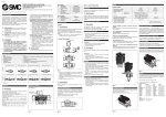
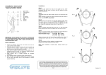
Cable-Tight™ Wire Management
System Installation Guide
Franklin Fueling Systems • 3760 Marsh Rd. • Madison, WI 53718 USA
Tel: +1 608 838 8786 • 800 225 9787 • Fax: +1 608 838 6433 • www.franklinfueling.com
Safety
Important!
UPP™ Systems must only be installed by fully trained and certified installers.
Failure to follow installation instructions will invalidate warranty and installer certification!
Piping Installation Safety
• UPP™ Welding Units must never be operated in Zone 1 or Zone 0 areas (Hazardous area definitions are from
European Directive 1999/92/EC and guidelines can be found in the APEA Blue Book 3rd Edition).
• Ensure Welding Units are connected to a power supply that meets the requirements detailed in the user manual
and are within the requirements of any local authority or regional legislation.
• Important to any type of piping system is to safely connect all metallic components to ground. Metallic
components, and more general conductive materials, due to their high capacitance, can have the potential to
store high amount of electrostatic energy (sparks discharge can only be observed over conductive elements).
• All exposed metal parts used in UPP™ System installations should be adequately grounded to a dedicated
earth electrode and brought to a potential equal to that of other metal parts in the close proximity.
Chemical Safety
Where using chemicals (such as Acetone) during the installation of UPP™ systems products, follow all safety
guidelines given on the chemical containers themselves or on any accompanying literature.
Confined Space
• Some installation of UPP™ products may occur in confined spaces where a lack of oxygen and a concentration
of toxic vapors is likely to be experienced.
• Such working conditions are dangerous and all local health and safety guidelines for working in such
environments should be followed.
Protective Equipment
• Ensure the correct personal protective equipment (PPE) is used at all times in line with local health and safety
requirements.
Material Safety Data
• Ensure all safety data is accessed and used while installing UPP™ Systems
Transport & Storage
• UPP™ products should be transported and stored in accordance with guidelines contained in this manual.
Heavy items
• Heavy items should be handled using suitable lifting equipment operated by authorised personnel.
Visually inspect all components before use to confirm there is no sign of damage.
Installation of ducting should be installed following UPP™ Systems Pipework Installation Instructions.
2
Cable-Tight™ Wire Management System
General Information
The Cable-Tight™ Wire Management System provides
a means of securely routing electrical conduit to and
between sumps / chambers and sealing the entries
against vapor and water intrusion.
Removable Separation
The chamber can be fitted with an optional removable
metal segregation panel that separates the IS
(Intrinsically safe ) wiring from the high voltage wiring by
creating two compartments.
Part number for the Segregation Panel is 408109001.
Removable Panel Creates Two Compartments
Installation
Installation of the electrical containment coincides with
the pipework and follows installation of the sumps/
chambers.
Install the Transition Chamber
Position the transition chambers in
accordance with local regulations.
Ensure correct burial depth to provide
drainage away from the chamber.
Transition Chamber Preparation
Prepare the area for the installation of the chamber taking
into account the burial depth for the desired finished
surface level. Anchor the electrical transition chamber
with wood or angle iron or most commonly set into
concrete to position it correctly
Feet on chamber
allow secure
mounting in
concrete
Pre-marked
drill centres
Top View of Transition Sump
Figure 2: Removable Panel
The transition chamber connects ducting from
the kiosk / control console to the conduit from the
sumps / chambers.
Ensure that the vapour seal to the kiosk
is leak-tight. Where required by local
regulations, ensure the duct termination
at the kiosk is terminated more than 1
meter above ground level.
Limit of concrete, front and back
Figure 1: Transition Sump
• Pre-marked drill centres allow optimized placement of
UPP™ entry seals in the side walls.
• Entry seals can be mounted before installing the
transition sump. (Follow electrofusion fitting installation
instructions).
From Kiosk / Console
To Sumps / Chambers
Figure 3: Transition Sump Connections
Frame
Bolt
Gasket
Draw Pit
Backing Plate
Connection detail
Figure 4: Sump Installation Detail
3
Installing Entry Seal Fittings
Incorrect selection or installation of
seal or seal plugs can lead to loss of
containment and may lead to transfer of
flammable vapours.
1.
2.
3.
4.
5.
Measure the diameter of each cable and
ensure they are fitted into the correct
holes of the Entry Seal.
The entry seal (303-075-EC) is first installed
with the compression nut removed following
electrofusion guidelines
Lightly attach the compression nut on the threads
of the entry seals.
Pull all wires / cables though to their final location.
Unscrew the compression nuts and let the nut
rest on the cables.
Follow instructions on Figures 5 through 9.
Figure 8: Push Entry Seal into the Entry Fitting
Figure 9: Tighten Compression Nut
Figure 5: Spread Cables and Insert Compression Disk
(See Table 1)
Tighten the compression nut hand-tight
plus an additional ½ turn using a strap
wrench, chain wrench or one as shown in
Figure 10.
Approved cable lubricant or liquid soap may be used on the
vapor gland to assist positioning the cables and tightening
the lock nut. Below are show two styles of wrenches that
can be used to tighten the compression nuts.
Figure 10: Compression Nut Wrenches
Figure 6: Tilt the Compression Disk to Insert Cables
Caution: Do NOT over-tighten the compression nut.
Over-tightening of the compression nut will
cause it to break.
Unused channels must be fitted with
cable plugs.
Cable plugs are available to insert into unused channels
in the vapor seal. Refer to Figure 7 and table 3
Figure 7: Insert Plugs
If required, insert plugs into unused channels prior to
tightening the compression nut.
4
Figure 11: The 32 mm Conduit Entry Seal fittings are
installed similarly to above.
Select the required Vapour Seal from Table 2.
Parts Tables
Image
Part Number
408102001
408103001
408113001
408122001
Number of Holes
x Cable Diameter
(approximate)
2 x 14-17 mm
1 x 11-14 mm
2 x 9-12 mm
12 x 5-8 mm
3 x 12-15 mm
6 x 7-10 mm
Blank
Typical Location
Dispenser Power and
Data (Non I. S.)
Tanks (I .S.)
Tank Power
(Pressure Only)
Line Testing and
Future Expansion
2 x 408029001
1 x 408131001
2 x 408132001
408134001
3 x 408130001
6 x 408133001
N/A
5
5
5
5
Corresponding Plug:
Quantity x
Part number
Pack Size
Table 1: Multi-Cable Compression Disks
Image
Part Number
408107006
408107005
408107004
408107003
408107002
408107007
Grommet Size
6 mm, (3)
9 mm
11 mm
14 mm
16 mm
Blank
Cable diameter
(approximate) mm
5 - 6
7- 9
9 - 11
12 - 14
14 - 16
N/A
Pack Size
10
5
5
5
5
10
Table 2: Compression Grommets
Image
Part Number
408128001
408129001
408130001
408131001
408132001
408133001
408134001
Grommet Size
25 mm
16 mm
14 mm
12 mm
11 mm
9 mm
6 mm
Pack Size
10
10
10
10
10
10
10
Table 3: Plug Table
Select the correct size of compression disk or compression grommet when replacing these items.
Follow Installation Instructions.
5
Installation 303-2DBC
Entry 2 x direct-buried cable
Ensure that the cables are buried at
depths as required by local regulations.
Note: Grommets are sold separately
1. Determine the location of the entry seal and
install it following electrofusion guidelines.
Installation 302-DBC
Entry direct-buried cable
Note: Ensure that the cables are buried at depths as
required by local regulations.
Note: Grommets are sold separately
1. Determine the location of the entry seal and
install it with the compression nuts removed,
following electrofusion guidelines.
Figure 12: Entry Seal for the 303-2DBC
Measure cable Ø and select the proper
size of grommets for cable size (refer to
table 2).
Figure 13: 303-2DBC Assembly
2. Route the first cable through entry seal, housing
grommet and compression nut.
3. Repeat with second cable.
Tighten the compression nuts hand tight
plus an additional ½ turn using a strap or
chain wrench.
Note: For a second seal on the cables , the backside
of the housing can be potted inside the housing
before electrofusion sealing “in” entry seal.
Figure 14: 302-DBC Entry Seal
Measure cable Ø and select the proper
size of grommets for cable size (refer to
table 2).
Figure 15: 302-DBC Assembly
2. Route the cable first through the compression nut
and grommet and then through the entry seal,
3. Pass cable through 2nd grommet and
compression nut.
Tighten the compression nuts hand tight
plus an additional ½ turn using a strap or
chain wrench.
4. Position the housing into entry seal so that the
threaded face is flush with entry seal. Weld
housing into entry seal following electrofusion
guidelines.
Figure 16: 302-DBC Assembled
6
Installation 305-3X27MM-CON
Entry 27 mm Rigid Conduit
Vacuum Testing
1. Determine the location of the entry seal and
install it following electrofusion guidelines.
The UPP™ Vacuum Test Unit VTU2 can be used to test
the joint between electrical chamber and all entry seals.
Recommended test setting: 1 ft: -30 mbar. Refer to the
Model VTU2 System Integrity Testing Kit Operation manual.
Note: Make sure plugs and blanks (see tables 1&2) are
positioned in entry seals and sealed.
Inside
Outside
PE Wall
Entry Seal
Figure 17: Entry Seal without Housing
2. Position housing into entry seal so that threaded
face is flush with entry seal. Weld housing into
entry seal following electrofusion guidelines.
Inside
Outside
UPP System Integrity Testing Unit
Figure 20: Vacuum Testing Electrical Transition Sump
IMPORTANT: Inspect all entry seals, vapour seals and
plugs to ensure all parts a correctly fitted
and sealing nuts hve been tightened.
Final Backfilling
( Electrical Transition Chamber)
Prior to backfilling the Access Cover must be in position
to prevent any deflection of the Chamber
Flush
Figure 18: Entry Seal with Housing Installed
Route rigid conduit at an axial alignment
to Entry Seal of no greater than ± 5
degrees through the housing and then the
grommet. Secure conduit in position by
tightening the nut. Hand-tighten nuts plus
an additional ½ turn using strap wrench
Housing
Outside
Grommet
Nut
Acceptable backfill materials are:
• Well-rounded pea gravel, size 3 mm (⅛") to
20 mm (¾").
• Crushed rock size 3 mm (⅛") to 16 mm (⅝").
• Clean washed sand.
Particular care should be taken to ensure that enough
backfill is laid down around the underside of the access
cover frame with enough concrete to fully support the
frame to withstand traffic loading.
IMPORTANT:Backfill material should fully support UPP™
pipe-work and be free from ice or organic
silt or peat, which could disappear over
time causing voids or possible ground
movement. No mechanical compactors
should be used such as vibrating plates,
compactors or road rollers.
Inside
Figure 19: Entry Seal with Conduit Installed
Note: If any opening are not used, seal with 25 mm plug
408128001 in the grommet.
7
Franklin Fueling Systems LTD
8 Olympus Close • Whitehouse Industrial Estate
Ipswich, Suffolk IP1 5LN • United Kingdom
Tel: +44 1473 243300 • Fax: +44 1473 243301
©2015 FFS 408123001 Rev 1