1
WebdynSun
The monitoring gateway for your solar installation
User’s Manual
MU-WebdynSun – V1.1
Table of Contents
1.
Glossary ..................................................................................................................................................... 6
2.
About this document .................................................................................................................................. 7
3.
2.1.
Scope ................................................................................................................................................. 7
2.2.
Target audience ................................................................................................................................. 7
2.3.
Product versions ................................................................................................................................ 7
2.4.
Safety advice ..................................................................................................................................... 8
Principles of operation ............................................................................................................................... 9
3.1.
4.
5.
6.
Overview diagram of a comprehensive monitoring solution. ............................................................. 9
Unit characteristics .................................................................................................................................. 10
4.1.
Technical characteristics ................................................................................................................. 10
4.2.
List of available interfaces ............................................................................................................... 11
4.3.
Options and accessories ................................................................................................................. 12
4.3.1.
DIN RAIL POWER SUPPLY .................................................................................................... 12
4.3.2.
GSM/GPRS right-angled stub antenna: .................................................................................. 14
4.3.3.
GSM/GPRS externally mounted antenna ................................................................................ 14
Prerequisites ............................................................................................................................................ 15
5.1.
Access to the FTP server ................................................................................................................ 15
5.2.
Access to the NTP server: ............................................................................................................... 16
5.3.
Connexion via GPRS or Ethernet: ................................................................................................... 16
5.3.1.
Ethernet connection: ................................................................................................................ 16
5.3.2.
GPRS connection: ................................................................................................................... 16
5.3.3.
Managing the PIN code for the SIM card: ............................................................................... 16
Configuring the unit .................................................................................................................................. 17
6.1.
Roles of the WebdynSun files.......................................................................................................... 17
6.1.1.
Configuration files .................................................................................................................... 17
6.1.2.
Definition files........................................................................................................................... 17
6.2.
Initialisation ...................................................................................................................................... 18
6.2.1.
Configuration via the built-in Web server................................................................................. 22
6.2.2.
Configuration via SMS ............................................................................................................. 27
6.3.
Setting the unit date and time .......................................................................................................... 28
6.4.
Connexion modes and periods ........................................................................................................ 29
6.4.1.
Manual connection ................................................................................................................... 29
6.4.2.
Periodic automatic connection ................................................................................................. 30
6.4.3.
Automatic connection at fixed times ........................................................................................ 30
2
MU-WebdynSun – V1.1
6.4.4.
Automatic connection on data capture .................................................................................... 31
6.4.5.
Keeping the connection open .................................................................................................. 32
6.4.6.
Automatic connection on alarm ............................................................................................... 32
6.4.7.
Optimising the connection ....................................................................................................... 32
6.5.
7.
8.
9.
Acquisition period and time slots ..................................................................................................... 33
Inverter management............................................................................................................................... 35
7.1.
Inverter wiring .................................................................................................................................. 36
7.2.
Inverter discovery ............................................................................................................................ 38
7.2.1.
Discovering inverters using the built-in Web server ................................................................ 38
7.2.2.
Discovering inverters via a command file ................................................................................ 39
7.3.
Declaring and configuring inverters ................................................................................................. 40
7.4.
Inverter definition files ...................................................................................................................... 43
7.5.
Checking that inverters are operating correctly ............................................................................... 44
7.6.
Inverter data ..................................................................................................................................... 45
7.6.1.
Filename syntax: ...................................................................................................................... 45
7.6.2.
Format of inverter data: ........................................................................................................... 45
7.6.3.
Example ................................................................................................................................... 46
7.7.
Inverter parameters ......................................................................................................................... 47
7.8.
Inverter alarms ................................................................................................................................. 48
7.8.1.
Filename syntax ....................................................................................................................... 48
7.8.2.
Format of alarms: ..................................................................................................................... 48
7.8.3.
Example of alarm file: .............................................................................................................. 48
TIC (smart) meter management .............................................................................................................. 49
8.1.
Smart meter wiring ........................................................................................................................... 50
8.2.
Smart meter discovery ..................................................................................................................... 51
8.2.1.
Discovering meters using the built-in Web server ................................................................... 51
8.2.2.
Discovering meters via a command file ................................................................................... 52
8.3.
Declaring meters .............................................................................................................................. 53
8.4.
Meter definition files ......................................................................................................................... 55
8.5.
Checking that meters are operating correctly .................................................................................. 57
8.6.
Meter data ........................................................................................................................................ 57
8.6.1.
Filename syntax: ...................................................................................................................... 58
8.6.2.
Format of meter data: .............................................................................................................. 58
8.6.3.
Example: .................................................................................................................................. 59
Input/output management ........................................................................................................................ 61
9.1.
Wiring ............................................................................................................................................... 61
9.1.1.
Analogue inputs (0–10 V or 4–20 mA) .................................................................................... 61
3
MU-WebdynSun – V1.1
9.1.2.
Switching relay outputs ............................................................................................................ 63
9.1.3.
Dry contact inputs .................................................................................................................... 63
9.1.4.
Index inputs: pulse counting .................................................................................................... 64
9.2.
Declaring input/output ports ............................................................................................................. 65
9.3.
Input/output definition files ............................................................................................................... 65
9.4.
Checking that input/output ports are operating correctly ................................................................. 67
9.5.
Input/output data .............................................................................................................................. 68
9.5.1.
Filename syntax: ...................................................................................................................... 68
9.5.2.
Format of input/output data:..................................................................................................... 68
9.5.3.
Example: .................................................................................................................................. 69
9.6.
Alarms on the dry loop inputs .......................................................................................................... 71
9.6.1.
Syntax of the alarms file name: ............................................................................................... 71
9.6.2.
Format of alarms: ..................................................................................................................... 71
9.6.3.
Example of an alarm on a dry loop: ......................................................................................... 71
9.7.
10.
Controlling relays via a command file .............................................................................................. 72
Modbus device management .............................................................................................................. 73
10.1.
Bus wiring .................................................................................................................................... 73
10.2.
Configuring and declaring Modbus slave devices ....................................................................... 75
10.3.
Structure of a Modbus definition file ............................................................................................ 78
10.4.
Checking that Modbus devices are operating correctly ............................................................... 82
10.5.
Modbus data ................................................................................................................................ 82
10.5.1.
Filename syntax: ...................................................................................................................... 82
10.5.2.
Data format: ............................................................................................................................. 82
10.5.3.
Example: .................................................................................................................................. 84
10.6.
10.6.1.
Alarm filename syntax: ............................................................................................................ 86
10.6.2.
Format of alarms: ..................................................................................................................... 86
10.6.3.
Example of alarm file: .............................................................................................................. 87
10.7.
11.
Modbus alarms ............................................................................................................................ 86
Writing Modbus variables via a command file ............................................................................. 88
Displaying operating data .................................................................................................................... 89
11.1.
Displaying cumulative variables................................................................................................... 89
11.2.
Displaying instantaneous variables ............................................................................................. 91
11.3.
Details of the definition file IDsite_REPORT.ini: .......................................................................... 91
12.
11.3.1.
Default definition file IDsite_REPORT.ini ................................................................................ 93
11.3.2.
Examples of IDsite_REPORT.ini configuration ....................................................................... 93
11.3.3.
Configuring a Siebert Modbus display ..................................................................................... 94
Command file ....................................................................................................................................... 96
4
MU-WebdynSun – V1.1
12.1.
GATEWAY type commands ........................................................................................................ 96
12.2.
I/O type commands ...................................................................................................................... 97
12.3.
MODBUS type commands........................................................................................................... 97
13.
Updating the unit: ................................................................................................................................. 98
13.1.
Updating via the Web server ....................................................................................................... 98
13.2.
Updating remotely via the FTP server ......................................................................................... 99
14.
Using Web Services .......................................................................................................................... 100
14.1.
Enabling and configuring ........................................................................................................... 100
14.2.
Format of HTTP requests .......................................................................................................... 100
14.3.
Examples of Web Services requests ......................................................................................... 103
15.
Tools and diagnostics ........................................................................................................................ 104
15.1.
Events journal ............................................................................................................................ 104
15.2.
Modem information .................................................................................................................... 106
15.3.
Detecting power connection ...................................................................................................... 107
15.3.1.
Syntax of the alarm file name: ............................................................................................... 107
15.3.2.
Format of alarms: ................................................................................................................... 107
15.4.
LED indicators............................................................................................................................ 108
15.5.
Installation button ....................................................................................................................... 109
15.6.
Diagnostic SMSs ....................................................................................................................... 110
15.7.
Debug traces.............................................................................................................................. 110
15.8.
Factory reset procedure ............................................................................................................. 112
15.9.
Support ...................................................................................................................................... 112
5
MU-WebdynSun – V1.1
1. Glossary
Name
Description
APN
Access Point Name
Name of the access point that enables the gateway to connect to the Internet via a
mobile link.
ERDF
Électricité Réseau Distribution France, the French National Grid, which defines
connection norms for installations and meters, especially smart meters. See TIC.
FTP
File Transfer Protocol
Communications protocol used to share data files on a TCP/IP network.
GPRS
General Packet Radio Service
Standard for mobile telephone communications derived from the GSM standard
and enabling higher data transfer rates. Also known as 2.5G.
DL: maximum 86 kbps
UL: maximum 43 kbps
GSM
Global System for Mobile Communications
The switched network for mobile telephones.
HTTP
HyperText Transfer Protocol
Client-server communications protocol developed for the Web.
IP
Internet Protocol
Message protocol controlling the addressing and transmission of TCP packets over
the network.
DIN Rail
Standardised 35-mm metal rail used in Europe for rack-mounted industrial control
equipment
PSTN
Public switched telephone network
Switched network for telephone land lines.
TCP
Transmission Control Protocol
A connection-oriented protocol for the Internet, which provides data segmentation
into packets that are transmitted over the network via the IP protocol. This protocol
provides a reliable data transfer service. See also IP.
TCP/IP
Transmission Control Protocol/Internet Protocol
The suite of network protocols that provide interconnection services between
computers with different hardware architectures and operating systems. TCP/IP
includes standards for communication between computers and conventions for
network interconnection and for routing.
TIC
“Télé-Information Client” [Remote Customer Information]
Digital data output port for ERDF smart meters, which provides constant output of
the contractual parameters managed, as well as the consumption figures measured
by the unit.
6
MU-WebdynSun – V1.1
2. About this document
The purpose of this guide is to describe the installation and operation of a WebdynSun gateway.
For all instructions pertaining to the installation and operation of inverters, please see the Appendices
corresponding to the individual inverters.
2.1. Scope
The present technical description is valid for WebdynSun gateways from hardware version 2 onwards, and
from software version V3.02.21 and up.
2.2. Target audience
This guide is intended for users of WebdynSun gateways.
2.3. Product versions
There are two versions of this unit:
WGE-G-PV: this model includes a GSM/GPRS modem.
WGE-R-PV: this model includes a PSTN/PSTN modem.
This manual covers only the WGE-G-PV variant. For all specific details concerning the WGE-R-PV variant,
please contact WebdynSun support.
7
MU-WebdynSun – V1.1
2.4. Safety advice
It is essential to respect all safety recommendations featured in this guide.
Failure to comply with these recommendations may cause damage to equipment and danger to the health
safety of personnel.
Electrical connections
-
All wiring must be carried out only by a specialised qualified electrician.
-
Prior to installation, all equipment connected to the corresponding communications
bus must be disconnected on both sides (DC and AC).
-
Respect all safety recommendations appearing in inverter documentation.
The WebdynSun unit is liable to damage from
electrostatic discharge (ESD)
Avoid all contact with component connectors and terminals
The WebdynSun unit contains a lithium battery
WARNING
RISK OF EXPLOSION IF THE BATTERY IS REPLACED
BY ANOTHER BATTERY OF AN INCORRECT TYPE.
DISCARD ALL WORN-OUT BATTERIES
IN COMPLIANCE WITH THEIR INSTRUCTIONS
8
MU-WebdynSun – V1.1
3. Principles of operation
The WebdynSun gateway is the communications hub for your solar generator. It continuously collects all the
data from inverters, sensors, electric meters and Modbus units. In this way, it enables you to be informed
constantly on the operational state of your installation.
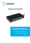
3.1. Overview diagram of a comprehensive monitoring solution.
Photovoltaic installation
Sensors
(temperature,
sun, etc.)
Electric
meters
Circuit breakers,
relays …
Inverters
Modbus
devices
Local PC (configuration)
Operation
FTP Server
Users
Internet
HTTP Server
Web Services
9
MU-WebdynSun – V1.1
4. Unit characteristics
4.1. Technical characteristics
Electrical characteristics
Input tension
12 / 24 V
Electricity consumption when idle
2.8 W (1)
Electricity consumption when connected via Ethernet
3.2 W (1)
Maximum peak power during GPRS connection
5 W (1)
Lithium-Ion battery
3.7V-650mA-2.4Wh
GSM/GPRS antenna: Microel EA-247
Frequency
900/1800 MHz
Gain
0 dB
Polarisation
Vertical
Memory
Storage capacity
100 MB of compressed data
Dimensions
Size
157mm*86mm*58.5mm
Environmental conditions
Operational temperature range
-10°C to +55°C
Storage temperature (for a period of less than one month)
-20°C to +45°C
Storage temperature (for a period of more than one month)
-20°C to +35°C
(1) Measurements carried out on the Unit + DIN Rail DR15-24 power supply assembly
10
MU-WebdynSun – V1.1
4.2. List of available interfaces
Data source
Interface
Characteristics
Inverters
RS485 (A) 2/4-wire, Ethernet
Maximum number depends
on the brand (1)
Electric meters
Remote customer
information (TIC)
Up to 3
Modbus devices
RS485 2/4-wire
Up to 247
Analogue sensors:
0-10V or 4-20mA
Up to 4
(temperature, light level, etc.).
2 wires + power
Resolution: 10 bits
Status sensors (open/closed)
Dry contact via 2 wires
Up to 4
Indicator lamp
Switching relay via 2 wires
Up to 2
Pulse counter, safety switch
Dry contact via 2 wires
Up to 2
(ERDF : Bleu, jaune, émeraude, PMEPMI)
(1) For the maximum number of inverters that the gateway can handle, please see the Appendix that
corresponds to their brand: Appendix-Brand-WebdynSun.pdf.
Communications channel
Protocol
Ethernet 10/100 Mbps
IP Services
GSM/GPRS Modem
IP Services
(WGE-G-PV)
Remote servers
Protocol
FTP server
FTP
HTTP server (Web Services option)
HTTP
NTP server
NTP
11
MU-WebdynSun – V1.1
4.3. Options and accessories
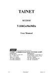
4.3.1.
DIN RAIL POWER SUPPLY
Brand: MEANWELL
Reference No.: DR-15-24
This power supply unit is mounted next to the gateway on the standard 35-mm DIN RAIL metal rail. This rail
mounting means that no other mounting bracket is required.
•
•
If the DIN RAIL unit is used to supply power remotely to analogue modules, please
check the output tension adjustment value.
In addition, check the power consumption of all remotely powered modules.
Characteristics:
OUTPUT
DC VOLTAGE
24V
RATED CURRENT
0.63A
CURRENT RANGE
0 ~ 0.63A
RATED POWER
15.2W
RIPPLE & NOISE (max.) Note.2
150mVp-p
VOLTAGE ADJ. RANGE
21.6 ~ 26.4V
VOLTAGE TOLERANCE Note.3
±1.0%
LINE REGULATION
±1.0%
LOAD REGULATION
±1.0%
SETUP, RISE TIME
1000ms, 50ms/230VAC
1000ms, 50ms/115VAC at full load
HOLD UP TIME (Typ.)
70ms/230VAC
16ms/115VAC at full load
12
MU-WebdynSun – V1.1
INPUT
VOLTAGE RANGE
85 ~ 264VAC
FREQUENCY RANGE
47 ~ 63Hz
EFFICIENCY (Typ.)
85%
AC CURRENT (Typ.)
0.88A/115VAC
120 ~ 370VDC
0.48A/230VAC
INRUSH CURRENT (Typ.)
COLD START 35A/115VAC
65A/230VAC
OVERLOAD Note.5
105 ~ 160% rated output power
Protection type: Constant current limiting,
recovers automatically after fault condition is
removed
PROTECTION
OVER VOLTAGE
27.6 ~ 32.4V
WORKING TEMP.
-20°C ~ +60°C (Refer to output load derating
curve)
WORKING HUMIDITY
20 ~ 90% RH non-condensing
STORAGE TEMP., HUMIDITY
-40°C ~ +85°C, 10 ~ 95% RH
TEMP. COEFFICIENT
±0.03%/ (0 ~ 50) °C)
VIBRATION
10 ~ 500Hz, 2G 10min./1cycle, period for 60min.
each along X, Y, Z axes; Mounting: Compliance
to IEC60068-2-6
SAFETY STANDARDS
UL60950-1, TUV EN60950-1 approved, design
refer to EN50178
WITHSTAND VOLTAGE
I/P-O/P: 3 KV AC
SAFETY &
ISOLATION RESISTANCE
I/P-O/P: 100 megohm / 500 V DC / 25 / 70% RH
EMC
EMI
CONDUCTION
RADIATION
ENVIRONMENT
&
Compliance to EN55011, EN55022 (CISPR22),
EN61204-3 Class B
HARMONIC CURRENT
Compliance to EN61000-3-2, -3
EMS IMMUNITY
Compliance to EN61000-4-2, 3, 4, 5, 6, 8, 11,
ENV50204, EN55024, EN61000-6-2, EN612043, heavy industry level, criteria A
MTBF
1172.3K hr min.
DIMENSION
25*93*56mm (W*H*D)
MIL-HDBK-217F (25 )
OTHERS
13
MU-WebdynSun – V1.1
4.3.2.
GSM/GPRS right-angled stub antenna:
Characteristics:
Frequency range
4.3.3.
900-1800 MHz
GSM/GPRS externally mounted antenna
Characteristics:
Cable:
RG-58
Cable length:
5,10 or 20 metres available
824-960 MHz
Frequency ranges
1710-1990 MHz
Options
Mounting bracket
14
MU-WebdynSun – V1.1
5. Prerequisites
Configuration of the WebdynSun is mainly carried out using configuration and definition files, which are
available on a remote FTP server. Consequently, it is vitally important that the WebdynSun gateway should
have access to an FTP server for downloading and/or uploading its configuration and definition files, as well
as its data, alarm and log files.
st
In addition, the factory default time and date setting of the gateway is 1 January 1970 at 00:00. Time
synchronisation is therefore required to enable the data to be correctly timestamped. For this purpose, the
gateway must synchronise itself with an NTP (Network Time Protocol) server.
For these reasons, it is important to ensure that the prerequisites listed below are correctly entered.
5.1. Access to the FTP server
For the configuration of the remote FTP server, it is essential to respect the following configuration:
-
Read/Write/Rename access authorised;
Passive mode enabled;
Port 21 (by default);
Short handshake message;
Login and Password must be less than 30 characters.
As the WebdynSun gateway does not create any directories, the FTP server must provide the directories and
subdirectories for configuration, definition, data, alarms, commands, logs and updates. Here is a list of the
default directories expected:
•
•
•
•
•
•
•
/CONFIG: Contains the configuration files for the gateway.
/DEF: Contains the definition files for the modules and sensors to be controlled:
o /INV: Definition files for inverters;
o /TIC: Definition files for electric meters;
o /IO: Definition files for analogue and digital input/output, and index entries;
o /MODBUS: Definition files for Modbus units;
o /REPORT: Definition files for variables to be displayed on the home page or on a display
panel.
/BIN: contains the binary files of the gateway for update purposes.
/DATA: Directory for upload of data files. This directory contains four subdirectories:
o /INV: inverter data;
o /TIC: electric meter data;
o /IO: Analogue and digital input/output data, and index entries;
o /MODBUS: Modbus data;
o /ID: Identification files for the gateway.
/ALARM: Contains the alarm files.
/CMD: Contains the command and acknowledgement files.
/LOG: Contains the gateway system log (IDSite_DATE.log) and the debug trace log (disabled by
default, and used only by Webdyn in support mode) IDSite_DATE_debug.log.
It is possible to modify part of the directory tree of the FTP server by modifying the root directories
(“/CONFIG”, “/DEF”, “/DATA”, “/BIN”, “/ALARM”, “/CMD” and “/LOG”) in the configuration of the WebdynSun
gateway.
15
MU-WebdynSun – V1.1
5.2. Access to the NTP server:
To set its date and time correctly, the WebdynSun synchronises itself with an NTP server before each
connection to the FTP server. By default, the gateway is configured to synchronise itself with the NTP server
“pool.ntp.org”. As this NTP server is accessible via the Internet, the gateways must have valid Internet
access (the UDP port 123 must be open for outgoing traffic) for synchronisation to occur.
5.3. Connexion via GPRS or Ethernet:
Access to the FTP and NTP servers may be via an Ethernet connection or a GPRS connection.
5.3.1.
Ethernet connection:
For connection via Ethernet, the following parameters must be supplied:
-
IP address of the WebdynSun on the local network;
Subnet mask;
IP address of the router or ADSL modem;
IP address of the DNS server.
5.3.2.
GPRS connection:
For connection via GPRS, it is essential to procure an activated SIM card with a DATA option, and to know
the values of the following parameters:
-
APN (Access Point Name): Name of the GPRS access point. This depends on the operator and the
type of subscription;
User name and password for connection to the APN.
5.3.3.
Managing the PIN code for the SIM card:
For connection via GPRS, a card must be inserted into the WebdynSun gateway. The PIN code to enable
access to the card cannot be entered on the gateway. The WebdynSun unit handles the PIN code for the
SIM card automatically. It is for that reason that the SIM card must either be initialised with no PIN code or
with a PIN code set to 0000 when it is first inserted.
The PIN code is managed using the following methods:
- If the PIN code is deactivated: GPRS communication is operational for the gateway.
- If the PIN code is activated and equal to “0000”: when the gateway is fired up for the first time, a
new PIN code is attributed to the SIM card. This PIN code is defined on the basis of the ICCID (Integrated
Circuit Card Identification) number of the SIM card installed. It is calculated using a proprietary Webdyn
algorithm. This feature allows fraudulent use of the SIM card to be prevented, while providing ease of use.
In addition, this same SIM card can be reused in another WebdynSun or WebdynTIC unit without any
additional configuration.
- If the card has a PIN code that is activated but is neither “0000” nor the code attributed by the
WebdynSun gateway, communications (including SMSs) will not be operational.
Never insert a SIM card with an activated PIN code that is neither “0000” nor a
value attributed by a WebdynSun. If you do so, the SIM card will be blocked and
the user will have to unblock it by entering the PUK code manually.
16
MU-WebdynSun – V1.1
6. Configuring the unit
Configuration of the WebdynSun gateway should be carried out in several stages. The first stage,
initialisation, consists of configuring the WebdynSun gateway so that it can connect to the FTP server.
During this stage, it is also possible to trigger the detection of inverters or meters so that these items can be
included in the configuration that will be uploaded to the FTP server. The second stage is configuration of the
gateway via the remote server. During this stage, it is possible to modify the whole set of configuration
parameters via the files available on the server, as well as to trigger the commands to detect inverters or
meters.
6.1. Roles of the WebdynSun files
Except for the locally accessible parameters enabling connection to the remote FTP server, all configuration
of the unit is performed via the configuration files available on the said server. The files available on the FTP
server must be in ANSI format.
Each configuration file is prefixed with a unique identifier named the “prefixID”. This prefix enables the
configuration for each gateway on the server to be customised. Two categories of files are necessary for
configuring the unit: the configuration files and the definition files.
The WebdynSun gateway does not overwrite the configuration and definition files available on the server.
Care must be taken to maintain consistency between the configuration of the gateway and the files on the
server. Where the configuration is modified locally, it is advisable to delete the files from the server so that
the gateway will recreate them. Conversely, if one of the files on the server is modified, the gateway detects
this and will download it. The standard configuration of the gateway is thus overwritten.
6.1.1.
Configuration files
The WebdynSun has three configuration files:
-
prefixID_config.ini: this contains the general parameters of the WebdynSun.
prefixID_daq.ini: this contains the parameters required for data acquisition.
prefixID_var.ini: this contains the information for scheduling connection and data acquisition times.
These 3 files are contained in the configuration directory on the FTP server. By default, this directory is
“/CONFIG”, but can be modified by means of the variable “FTP_DirConfig” in the file prefixID_config.ini.
If the gateway does not detect these files on the FTP server, it creates them from its current configuration.
Furthermore, at every connection to the server, the gateway checks the modification dates and sizes of the
files, in order to detect any modification of one of the files. Should a modification be detected, the file is
downloaded by the gateway.
The details of each parameter in the configuration files will be explained as required in the remainder of this
documentation.
6.1.2.
Definition files
The role of the definition file is to define the set of data to be collected for a given type of module. It may be
generated automatically by the WebdynSun unit or created by the IT department depending on the specific
details of the module that is to be managed.
The WebdynSun therefore possesses as many definition files as there are types of module to be controlled.
The link between the definition files and the unit is provided via the configuration file prefixID_daq.ini.
A detailed description of an inverter definition file is provided in the inverter-specific appendices.
17
MU-WebdynSun – V1.1
6.2. Initialisation
Initial configuration of the unit is necessary to enable connection to the remote FTP server. This configuration
can be carried out either via the built-in Web server, or by SMS if this option is available where connexion is
done using GPRS.
Local configuration of the WebdynSun affects only the variables in the configuration file: prefixID_config.ini.
Here is a list of the variables accessible via the local web interface (http) and/or via SMS commands:
Variable
ID
Definition
Default value
HTTP
Gateway identifier
X
(up to 29 characters)
WDxxxxxx
where
xxx… is the last 6
digits of the MAC
address
Type of inverter protocol used:
0
X
192.168.1.12
X
0= SMA: SMA Net
1= PowerOne: Aurora
2= Schneider Electric: SunEzy
3= Kaco: Powador
4= Ingeteam
5= LTI
6= Fronius
7= Schneider ConextCom
8= Danfoss ComLynx
INV_Type
9= PowerOne (Manual
addressing)
10= Siemens PVM /Refusol
11= DiehlAko Platinum
12= SMA CENTRAUX Modbus
TCP
13= SOCOMEC SunSysHome
14= SOCOMEC SunSysPro
15= reserved
16= Ingeteam Modbus TCP
17= SolarMax MaxComm
18= Delta
LAN_IpAddr
IP address of the gateway
(router) on the LAN (local area
network)
Communication via Ethernet
18
SMS
MU-WebdynSun – V1.1
(up to 15 characters)
LAN subnet mask
LAN_SubnetMask
255.255.255.0
X
0.0.0.0
X
0.0.0.0
X
0
X
m2minternet
X
X
sfr
X
X
sfr
X
X
*99***1#
X
X
empty
X
empty
X
Communication via Ethernet
(up to 15 characters)
Address of the gateway (router)
on the LAN
LAN_Gateway
Communication via Ethernet
(up to 15 characters)
Address of the DNS server on
the LAN
LAN_DNS
Communication via Ethernet
(up to 15 characters)
Enable/Disable DHCP:
LAN_DHCP_Enable
For automatic provision of
Ethernet IP addresses.
0=Disabled
1=Enabled
GPRS Access Point Name
(APN)
GPRS_APN
Provided by mobile operator
(up to 29 characters)
GPRS APN identifier
GPRS_Login
Provided by mobile operator
(up to 29 characters)
GPRS APN password
GPRS_Password
Provided by mobile operator
(up to 29 characters)
Phone number for GPRS
GPRS_PhoneNumber
In France: *99***1#
(up to 13 characters)
Phone number for PSTN
FAI_PhoneNumber
Provided by the Internet
Service Provider (ISP).
(up to 13 characters)
PSTN identifier
FAI_Login
Provided by the ISP
19
MU-WebdynSun – V1.1
(up to 29 characters)
PSTN password
FAI_Password
empty
X
1
X
empty
X
X
empty
X
X
empty
X
X
Port used for connexion to
remote FTP server
21
X
X
FTP directory name for
gateway configuration files
/CONFIG
X
/DEF
X
/DATA
X
/LOG
X
/BIN
X
/ALARM
X
Provided by the ISP
(up to 29 characters)
Remote server connexion
interface selected:
WAN_ConnectionInter
face
0=Ethernet
1=modem (GPRS or PSTN
depending on unit version)
Name of remote FTP server
FTP_Server
(up to 29 characters)
FTP_Login
Identifier for connexion to
remote FTP server
(up to 29 characters)
FTP_Password
Password for connexion to
remote FTP server
(up to 29 characters)
FTP_Port
FTP_DirConfig
(up to 29 characters)
FTP_DirDef
FTP directory name for
gateway definition files
(up to 29 characters)
FTP_DirData
FTP directory name for data
files
(up to 29 characters)
FTP directory name for log files
FTP_DirLog
(up to 29 characters)
FTP directory name for
gateway firmware
FTP_DirBin
Used for upgrading gateway
(up to 29 characters)
FTP_DirAlarm
FTP directory name for alarm
files
(up to 29 characters)
20
MU-WebdynSun – V1.1
FTP directory name for
command files
FTP_DirCmd
/CMD
X
0
X
0
X
(up to 29 characters)
Enable/Disable of two-phase
data uploading. (File with
extension “.tmp” uploaded,
then extension “.tmp” deleted
after transfer.
FTP_Option
0=Disabled
1=Enabled
Enable/Disable of web
services:
WebService_Enable
0= Disabled
1= Enabled
Web Service http:// address
X
WebService_Url
(up to 29 characters)
Language chosen for built-in
website:
Language
fr
X
fr = French
en= English
These variables can be modified at any time on the remote server.
The server configuration always overrides the local configuration via the web
interface. Please ensure that the two configurations are consistent.
To ensure consistency between the server and the unit, it is advisable to delete the
unit’s configuration file prefixID_config.ini from the remote server as soon as any
local modification is carried out. This must be done before connecting, so that the
gateway can upload its new prefixID_config.ini configuration file.
21
MU-WebdynSun – V1.1
6.2.1.
Configuration via the built-in Web server
Access to the built-in Web interface on the WebdynSun gateway is provided via the gateway’s LAN
connection. As the gateway does not cross Ethernet signals, when there is a direct connection between the
gateway and the computer, a crossover cable must be used. In addition, both the computer used and the
gateway must belong to the same subnet. If the WebdynSun gateway has a static IP address (the default
situation), the computer must also be configured to use a compatible static IP address.
This static address must belong to the same subnet as the WebdynSun gateway.
On delivery, the settings for the WebdynSun gateway are as follows:
-
IP address: 192.168.1.12
Subnet mask: 255. 255. 255.0
Network administrator
-
If your local network is managed by a network administrator, contact him or her
before connecting the WebdynSun gateway up to your network.
Connecting to the built-in Web interface:
1. Once your computer has been correctly configured:
2. Launch your Web browser (Internet Explorer, Firefox, etc.).
3. Go to the home page of the WebdynSun gateway using the browser’s address bar to specify the
address http://192.168.1.12.
4. The following window is displayed:
5. Key in the identifier and the password:
On delivery, the settings of the WebdynSun gateway are as follows:
User Name: userhigh
Password: high
22
MU-WebdynSun – V1.1
6. The following home page is displayed:
If the gateway is not yet operating, the following message is displayed:
General configuration:
The Configuration page allows you to:
•
•
•
•
Choose the Web interface language.
Configure the gateway identifier
Complete the PSTN / GPRS / Ethernet connection parameters, and the http/ftp servers.
Choose the inverter protocol to be used.
23
MU-WebdynSun – V1.1
Choosing the language:
Selection the Web interface language from the popup menu.
This field corresponds to the variable “Language” in the configuration file prefixID_config.ini.
Gateway identifier:
This field corresponds to the variable “ID” in the configuration file prefixID_config.ini. The value of
this variable enables identification of the gateway when interacting with the FTP server. The names
of the files available on the server will be prefixed with the value of this variable, so as to link them to
the gateway (i.e. the site) concerned.
There are two ways of configuring the gateway identifier:
•
•
Manually, in the ID field (by default “ID=WDXXXXXX” where XXXXXX is the last six digits of the
MAC address).
Automatically, by ticking the Automatic mode checkbox and leaving the ID field empty (“ID= “). For
this option, Web Services must be enabled. The gateway will pick up its identifier just before the
initial connection to the FTP server. The ID will be filled in with the value returned by the Web
Services server. Should the variable “ID” be deleted once more (“ID= “), the gateway will request a
new identifier on its next connection.
24
MU-WebdynSun – V1.1
Connection mode:
Choose “Ethernet” or “Modem”, depending on the mode to be used for the connection.
Ethernet:
If the connexion mode chosen is “Ethernet”, enter parameters that are valid for your Ethernet
network:
-
-
-
Address mode: you can obtain the Ethernet parameters automatically if the network infrastructure
and the version of the WebdynSun can handle this. If this is the case, click the dynamic radio button
and consult the configuration of your DHCP server to find the IP address attributed to your gateway.
IP Address: enter the IP address at which the WebdynSun gateway is accessible.
Mask: enter the subnet mask for your network. This mask limits the Ethernet network to one range of
defined IP addresses, and separates one network range from another.
Gateway: enter the address of the gateway to your network. The gateway address is the IP address
IP of the device that establishes the connexion to the Internet. In general, the address entered here
is that of the router or ADSL modem.
DNS: enter the address of the DNS server. The DNS (Domain Name System) server translates
symbolic Internet addresses (e.g. “www.webdyn.com”) into their corresponding IP addresses. Here
you should enter the address of the DNS server you received you’re your Internet Service Provider
(ISP). You can also enter the IP address of your router or ADSL modem.
If your Ethernet network is managed by a network administrator, contact him or her to
have your WebdynSun gateway included in the existing Ethernet network.
Modem:
If the connexion mode chosen is “Modem”, enter parameters that are valid for your GPRS
subscription:
o
o
o
o
Call number: enter the phone number for the GPRS connection. The default number is
“*99***1#”, which is valid in most cases. This number is not the phone number of the SIM
card fitted to the unit.
APN: enter the Access Point Name (APN) supplied by your mobile operator.
Login: enter the user ID for the APN supplied by your mobile operator.
Password: enter the password for the APN supplied by your mobile operator.
Consult your mobile operator to obtain the information pertaining to your SIM card (APN,
user ID and password).
25
MU-WebdynSun – V1.1
FTP server:
To enable the gateway to communicate with a remote FTP server (via Ethernet OR modem), enter
the following information:
-
Server: IP Address or symbolic name of the remote FTP server.
Login: User ID used by the gateway for connection to the remote FTP server.
Password: Password used by the gateway for connection to the remote FTP server.
Port: Port number used for communications with the remote FTP server (default: 21).
Setup: Name of the Configuration directory (default: /CONFIG).
Definition: Name of the Definition directory (default: /DEF).
Data: Name of the Data directory (default: /DATA).
Alarms: Name of the Alarms directory (default: /ALARM).
Commands: Name of the Commands directory (default: /CMD).
Log: Name of the Log directory (default: /LOG).
Firmware: Name of the directory for downloading new firmware (default: /BIN).
Check that the FTP directories defined actually exist on the FTP server. The
gateway does not create any directories on the server.
For UNIX servers, the names are case sensitive (lower/UPPER case).
Web Services:
If the gateway has to use a connection to Web Services, enable this option and fill in the URL of the
server.
Otherwise, disable this option.
Inverter protocol:
Select the inverter protocol that you use from the popup menu.
Once all the parameters have been specified, click on OK.
A message will appear at the top of the page to indicate that the gateway must be
restarted to take the new parameters into account.
Click on Restart in the menu on the left and confirm this in the dialogue box:
Wait for the WebdynSun gateway to complete the restart, then reconnect to the built-in Web server.
26
MU-WebdynSun – V1.1
It is advisable to force connection to the remote server after restarting the unit.
This is to check that all the new parameters are correct.
To ensure consistency between the server and the unit, it is advisable to delete the
configuration file prefixID_config.ini from the unit before connecting. In this case,
the gateway will generate and upload a new prefixID_config.ini file.
6.2.2.
Configuration via SMS
It is possible to configure the information required for connection to the remote FTP server via SMS. To do
so, you must first insert an active GPRS SIM card into the WebdynSun unit and ensure that you know its
telephone number.
SMS to configure the APN:
Send the following SMS to the WebdynSun:
“apn=apn_name;usr=user_name;pwd=password;”
Where:
apn_name: Name of the APN.
user_name: User ID for access to the APN.
password: Password for access to the APN.
SMS to configure the remote FTP server:
Send the following SMS to the WebdynSun:
“ftp=server_name:user_name:password:port;”
Where:
server_name: Symbolic name or IP address of the remote FTP server.
user_name: User ID for access to the remote FTP server.
password: Password for access to the remote FTP server.
port: TCP port number for access to the remote FTP server (default: 21).
It is advisable to force connection to the remote server after restarting the unit. This is to
check that all the new parameters are correct.
SMS to connect to the remote FTP server:
Send the following SMS to the WebdynSun:
“Connect”
27
MU-WebdynSun – V1.1
To ensure consistency between the server and the unit, it is advisable to delete the
configuration file prefixID_config.ini from the unit before connecting. In this case, the
gateway will generate and upload a new prefixID_config.ini file.
6.3. Setting the unit date and time
The WebdynSun unit timestamps all its data and log entries. As a result, it is necessary to set its time and
date reliably. The real-time clock is therefore synchronised with a remote NTP server as a matter of course
every time the unit connects to the Internet.
To choose an NTP server, you must modify the variables listed below in the prefixID_config.ini configuration
file available on the server, then force the unit to connect to the remote server.
Variable
Definition
Default value
IP address for the main NTP server
pool.ntp.org
NTP_Server1
(up to 29 characters)
IP address for the backup NTP server
empty
NTP_Server2
(up to 29 characters)
An option to force NTP resynchronisation after a restart following a power failure is enabled by setting to 1
the variable “NTP_SyncPowerLoss” in the configuration file prefixID_config.ini.
Variable
NTP_SyncPowerLoss
Definition
Default value
Option to force NTP resynchronisation after a power
failure.
0
If this option is enabled, an NTP connection will be
established after the gateway restarts following a
power failure.
0=Disabled
1=Enabled
All timestamping of data and events is carried out using GMT.
28
MU-WebdynSun – V1.1
6.4. Connexion modes and periods
There are four modes of connection to a remote server:
-
Manual connection
Periodic automatic connection
Automatic connection at fixed times
Automatic connection on data capture
Automatic connection on alarm
In the case of automatic connection, the connection type is chosen depending on the prefixID_var.ini
configuration file.
The WebdynSun always carries out the same tasks, regardless of the type of connection requested:
-
NTP synchronisation
Connection to the remote FTP server
o Alarm management
o Command file management
o Data management
Upload of input/output data files
Upload of electric meter files
Upload of inverter data files
Upload of Modbus data files
o Configuration file management
o Definition file management
o Log management
o Firmware update management
6.4.1.
-
Manual connection
Connection by pressing the push-button:
You can force a connection manually by using a tool to press and hold the push-button labelled “INSTALL”
until the “SERVICES” LED begins to flash rapidly.
-
Connection via the built-in Web server:
You can force a connection manually via the built-in Web interface by going to the “Install/Connection” menu
and clicking on the “Connect” button.
-
Connection via SMS:
Send the SMS “connect” to the WebdynSun to force immediate connection.
29
MU-WebdynSun – V1.1
6.4.2.
Periodic automatic connection
Periodic automatic connection consists of providing the WebdynSun with a period for connection to the
remote server. This period is expressed in hours and is repeated every day.
This is done by using the variables “Connection_Period”, “Connection_Hour” and “Connection_Minute” in the
configuration file prefixID_var.ini.
Variable
Definition
Connection_Period
Default value
Period for connection to the remote FTP server (in
hours, range 0 to 23)
0
If >0: number of hours between two connections. The
variable “Connection_Minute” is used to specify the
minute number within the hour for the connection.
If =0: connection every day at the time specified by the
variables “Connection_Hour” and “Connection_Minute”
Connection_Hour
Hour for connection to the remote FTP server
1
Connection_Minute
Minute for connection to the remote FTP server
0
Example:
Configuration:
Connection_Period=7
Connection_Minute=25
Connection time:
Day d: 00:25, 07:25, 14:25, 21:25.
Day d+1: 00:25, 07:25, 14:25, 21:25.
6.4.3.
Automatic connection at fixed times
Automatic connection at fixed times consists of programming the WebdynSun with up to 5 times for
connecting to the remote server per day.
This mechanism is taken into account only if the variable “Connection_Period” is equal to 0.
Programming the connection times is carried out by updating the variables listed below in the configuration
file prefixID_var.ini.
Variable
Definition
Default
value
Connection_Hour
Hour for connecting to remote FTP server
1
Connection_Minute
Minute for connecting to remote FTP server
0
Connection_Hour1
Hour for connecting to remote FTP server
0
Connection_Minute1
Minute for connecting to remote FTP server
0
30
MU-WebdynSun – V1.1
Connection_Hour2
Hour for connecting to remote FTP server
0
Connection_Minute2
Minute for connecting to remote FTP server
0
Connection_Hour3
Hour for connecting to remote FTP server
0
Connection_Minute3
Minute for connecting to remote FTP server
0
Connection_Hour4
Hour for connecting to remote FTP server
0
Connection_Minute4
Minute for connecting to remote FTP server
0
Example:
o
Configuration:
Connection_Hour=7
Connection_Minute=5
Connection_Hour1=12
Connection_Minute1=10
Connection_Hour2=18
Connection_Minute2=15
o
Connection times:
Day d: 07:05, 12:10, 18:15.
Day d+1: 07:05, 12:10, 18:15.
6.4.4.
Automatic connection on data capture
Automatic connection on data capture consists of instructing the WebdynSun to connect to the remote FTP
server so as to upload the newly captured data as soon as it is available. This is configured by setting the
variable “Connection_OnDataAcquisition” in the configuration file prefixID_var.ini to 1.
In this operating mode, configuration checking and time synchronisation still take place according to the
parameters for connecting periodically or at fixed times as shown in the foregoing chapters.
Example:
o
Configuration:
Connection_OnDataAcquisition=1
Connection_Period=0
Connection_Hour=23
Connection_Minute=0
And the data capture period is defined to be 15 minutes:
DAQ_Period=15
o
Connection times:
Every 15 minutes for uploading data
At 23:00 for time synchronisation and configuration checking.
31
MU-WebdynSun – V1.1
6.4.5.
Keeping the connection open
With a view to optimising the connection when automatic connection on data capture has been enabled, it is
possible to keep the connection open to avoid pointless disconnections and reconnections.
This is carried out by correctly configuring the variable “Connection_WaitBeforeCloseDelay” in the
configuration file prefixID_var.ini.
This delay, which is expressed in minutes, must be greater than the data acquisition time
“DAQ_Period” defined in the file prefixID_daq.ini. The maximum authorised value is 59 minutes.
Example:
o
Configuration:
Connection_OnDataAcquisition=1
Connection_WaitBeforeCloseDelay=5
Connection_Period=0
Connection_Hour=23
Connection_Minute=0
And the data acquisition period is defined as 2 minutes:
DAQ_Period=2
o
Connection times:
Connection kept open with data being uploaded every 2 minutes
Time synchronisation and configuration checking occurs at 23:00 every day.
6.4.6.
Automatic connection on alarm
By default, the WebdynSun will trigger a connection to the remote FTP server immediately after the alarm
will be detected. However, to limit the number of exchanges with FTP server, it’s possible to disable this
functionality and to delay the connection at the next acquisition point. In this second case, the product will
collect all the alarms and they will be uploaded to the FTP server after the next acquisition point.
To enable or disable this functionality, you must change the value of the variable « ALM_Delay » in the file
prefixID_var.ini.
Variable
Définition
Défaut
ALM_Delay
0 : Alarms sent in real time
0
1 : Alarms sent after the next acquisition point (by
default 10 minutes)
6.4.7.
Optimising the connection
To avoid excessive GPRS consumption, it is possible to enable an optimisation option for FTP
communications. This is specified through the variable Connection_CheckConfigPeriod in the configuration
file prefixID_var.ini.
32
MU-WebdynSun – V1.1
When this optimisation is enabled, the gateway can be programmed not to analyse the configuration and
definition directories on every connection.
Variable
Definition
Connection_CheckConfigPeriod
Default value
0: Disabled
0
n: Number of days between 2 analyses.
Note:
When the gateway processes a
command file, it goes on to analyse the
configuration and definition directories
regardless of whether optimisation has
been enabled.
Where the variable Connection_Period is zero, the time for the analysis is defined by the variable
Connection_Hour. If it is not, the gateway will launch the analysis during the first connection of the day.
6.5. Acquisition period and time slots
The role of the WebdynSun is to collect data from different sources (inverters, meters, sensors, etc.), and
then to write them periodically to CSV files for provision via a remote FTP server.
Data collection is scheduled using the variables DAQ_Period and DAQ_PeriodSec in the configuration file
prefixID_daq.ini.
Variable
Definition
Comments
Default
value
DAQ_Period
Collection interval in minutes
common to all data sources
(Inverters, TIC, I/O, Modbus)
Possible value from 0
to 59 minutes
10
DAQ_PeriodSec
Collection interval in seconds
common to all data sources
(Inverters, TIC, I/O, Modbus)
Possible value from 0
to 59 seconds
0
Considered only if DAQ_Period
is equal to 0.
If the collection period configured is less than the real data acquisition period, the
data will be timestamped at the acquisition period.
A data acquisition time slot can be defined using the variables listed below, in the file prefixID_var.ini.
Variable
Definition
33
Default value
MU-WebdynSun – V1.1
DAQ_TimeZoneStartHour
Acquisition start hour
0
DAQ_TimeZoneStartMinute
Acquisition start minute
0
DAQ_TimeZoneStopHour
Acquisition end hour
0
DAQ_TimeZoneStopMinute
Acquisition end minute
0
34
MU-WebdynSun – V1.1
7. Inverter management
The WebdynSun can manage up to 100 inverters. However, this limit may be lowered in accordance with the
recommendations of each manufacturer.
The WebdynSun behaves differently according to the type and brand of inverter that you wish to monitor.
This is why it is important to follow the instructions from the corresponding Appendix available on our
website: http://www.WebdynSun.com.
Depending on the manufacturer and on the type of inverter, it is possible to:
-
Detect the inverters available on the bus.
Change the addresses of the inverters.
Collect the list of data that can be used.
Modify the parameters of the inverters.
The information provided below gives an overview of how the WebdynSun operates when connected to
inverters, but does not replace the Appendices.
35
MU-WebdynSun – V1.1
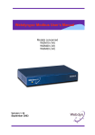
7.1. Inverter wiring
The gateway can handle three different types of inverter architecture: RS485 Half-Duplex, RS485 FullDuplex and Ethernet. Only one option can be chosen, and the protocol used must be selected in the
configuration file prefixID_config.ini, or via the built-in Web interface from the “Configuration” menu.
For connection via RS485, it may be necessary to enable the bus termination resistors, or leave them
disabled. Depending on the positioning of the gateway on the bus, this terminator must be enabled or
disabled via a pair of jumpers (JMP3 and JMP2) fitted inside the casing.
Configuration of bus
termination jumper
RS485 2 wires – Half Duplex
JMP3 and JMP2
JMP3 JMP2 JMP3 JMP2
ENABLE
DISABLE
RS485 4 wires – Full Duplex
JMP3 JMP2 JMP3 JMP2
ENABLE
See the Appendix for the inverters for details of their connections and wiring.
36
DISABLE
MU-WebdynSun – V1.1
RS485 Half-duplex (2 wires)
RS485 (A)
Ethernet Connection
RX+ RX- TX+ TXLAN
13 14 15 16
Ethernet Switch
100Mbit/s
D+
D-
Inverter 1
Inverter 1
Inverter 2
Inverter N
Inverter N
RS485 Full-duplex (4 wires)
RS485 (A)
RX+ RX- TX+ TX13 14 15 16
Inverter 1
37
Inverter 2
Inverter N
MU-WebdynSun – V1.1
7.2. Inverter discovery
This chapter is only applicable if the selected inverter protocol provides the facility to discover the inverters
available on the network. For more details, please see the corresponding Appendix.
7.2.1.
Discovering inverters using the built-in Web server
It is possible to perform inverter detection via the built-in Web server. This is triggered by going to the “Install”
menu and selecting “Inverter discovery”.
To launch the detection process, follow these steps:
1. Enter the number of inverters to be detected.
2. Click on the “Launch” button.
The following page is displayed:
3. The page refreshes itself automatically.
4. Wait until the message in green text “Discovery in progress” disappears.
While this task is being executed, no other tasks may be running. If there are any, a
warning message will be displayed at the top of the page, such as: A 'X' task is already in
progress. Please try again in a few moments.
After the search, a table is displayed at the bottom of the page, showing the types and descriptions of the
inverters detected:
38
MU-WebdynSun – V1.1
The discovery result is stored in a file named prefixID_INV.ini. This file is uploaded to the /CONFIG directory
of the FTP server during the next connection to the server. The file contains the full set of information that
characterises the inverters discovered. It complies with the following format:
INV_SN[n]=serialNumber
INV_Type[n]=inverterType
INV_Addr[n]=inverterAddress
Where:
n: index of the inverter discovered (0 to 99)
serialNumber: serial number of the inverter (format defined by manufacturer).
inverterType: model number of the inverter (format defined by manufacturer).
inverterAddress: address of the inverter on the bus (defined by manufacturer).
Example:
INV_SN[0]=2000388220
INV_Type[0]=WR21TL09
INV_Addr[0]=0xCC00
Until the inverters detected are declared in the configuration file prefixID_daq.ini,
no data will be collected. See the following chapter, “Declaring and configuring
inverters”.
7.2.2.
Discovering inverters via a command file
Some tasks, known as “commands”, may be requested remotely from the WebdynSun. These commands
are transmitted to the gateway in the form of files uploaded to the FTP server (prefixID_CMD.csv). This file
can contain several types of commands, including the command to discover inverters.
Command file: prefixID_CMD.csv.
The parameters of the commands depend on the type of command sent, as indicated below:
index;GATEWAY;GET_INV_NETWORK;nbInverter
Where:
index
1 to N: Unique identifier providing command identification
nbInverter
Number of inverters to be discovered
The command file is deleted from the server by the gateway after downloading. After the commands are
executed, an acknowledgement file is sent to the server (prefixID_ACK_YYMMDD_hhmmss.csv).
39
MU-WebdynSun – V1.1
Acknowledgement file: prefixID_ACK_YYMMDD_hhmmss.csv.
The acknowledgement file mirrors the command file, with timestamps added, and the acknowledgement:
Date-time;index;GATEWAY;GET_INV_NETWORK;nbInverter;;ack
Where ack=OK or ERROR.
The acknowledgement indicates whether the command was understood by the gateway. It gives no
information as to whether inverter detection succeeded or failed.
Until the inverters detected are declared in the configuration file prefixID_daq.ini,
no data will be collected. See the following section “Declaring and configuring
inverters”.
7.3. Declaring and configuring inverters
It is essential to select the inverter protocol to be used before declaring the inverters. This is done by
modifying the variable “INV_Type” in the configuration file prefixID_config.ini as follows:
Variable
Definition
Default Value
Type of inverter protocol used:
0
0= SMA: SMA Net
1= PowerOne: Aurora
2= Schneider Electric: SunEzy
3= Kaco: Powador
4= Ingeteam
5= LTI
6= Fronius
7= Schneider: ConextCom
INV_Type
8= Danfoss: ComLynx
9= PowerOne: (Manual addressing)
10= Siemens: PVM/Refusol
11= DiehlAko: Platinum
12= SMA CENTRAUX: Modbus TCP
13= SOCOMEC: SunSysHome
14= SOCOMEC: SunSysPro
15= reserved
16= Ingeteam: Modbus TCP
17= SolarMax: MaxComm
18= Delta
40
MU-WebdynSun – V1.1
Each inverter to be monitored must be declared in the configuration file prefixID_daq.ini.
This can be done manually by completing the fields listed below in the file prefixID_daq.ini, or automatically
after launching an inverter discovery phase, where this phase is available.
Parameters that are common to all interfaces:
Variable
Definition
Comments
Default
value
DAQ_Period
Collection interval in minutes
common to all data sources
(Inverters, TIC, I/O, Modbus)
Possible value from 0
to 59 minutes
10
DAQ_PeriodSec
Collection interval in seconds
common to all data sources
(Inverters, TIC, I/O, Modbus)
Possible value from 0
to 59 seconds
0
Considered only if DAQ_Period
is equal to 0.
DAQ_HeaderOption
Enable/Disable display of column
headers in the data files
0
0=disabled
1=enabled
Generic parameters for all inverters:
Variable
INV_nbDeviceByLog
Definition
Comments
Default
value
0
Number of INV devices per
data file:
0 = all devices are in a single
data file.
Parameters specific to each inverter:
Variable
Definition
Comments
INV_SN[n]
Serial number of inverter n
INV_FileDefName[n]
Name of
inverter n
Default
value
n=0 to 99
empty
for
n=0 to 99
empty
Supplementary data used for
some protocols
n=0 to 99
empty
definition
file
(up to 59 characters)
INV_INFO[n]
(up to 59 characters)
41
MU-WebdynSun – V1.1
42
MU-WebdynSun – V1.1
Example:
Declaration of 2 SunnyBoy SB 2100 TL inverters from SMA.
INV_SN[0]=2000499018
INV_FileDefName[0]=prefixID_INV_WR21TL09.ini
INV_SN[1]=2000509010
INV_FileDefName[1]=prefixID_INV_WR21TL0A.ini
To generate the file prefixID_daq.ini automatically, after launching a discovery phase, you must proceed as
follows:
1- Delete the file prefixID_daq.ini from the FTP server.
2- Force connection between the WebdynSun and the server via the web page, the push-button or an
SMS.
3- The gateway will regenerate a prefixID_daq.ini file, with the local information that it has gathered
during its inverter discovery phase.
7.4. Inverter definition files
Every inverter declared in the configuration file prefixID_daq.ini must have an associated definition file. The
purpose of this file is to describe the whole set of variables available for the inverter.
For each variable, it describes:
- Collection method: used by the gateway to collect the data from within the inverter.
- Processing method: average, instantaneous, parameter or alarm.
- Formatting: name, unit and scaling coefficient.
This file must be made available to the gateway on the FTP server.
By convention, the filename has the following format:
prefixID_INV_inverterType.ini,
Where: “prefixID” corresponds to the gateway identifier and “inverterType” corresponds to the type or
version of the inverter.
A single file may be used for many types of inverter that behave in the same way.
An INV definition file respects the following format:
index;reserved1;reserved2;reserved3;name;unit;coeffA;coeffB;action
index_N;reserved1_N;reserved2_N;reserved3_N;name_N;unit_N;coeffA_N; coeffB_N;action_N
43
MU-WebdynSun – V1.1
Where:
index_N
Index of the variable to be collected (1 to n). This index must be unique within the file.
reserved1_N
Fields specific to the chosen inverter protocol
reserved2_N
Note: these fields are not user-modifiable.
reserved3_N
name_N
Variable name
unit_N
Variable unit
coeffA_N
Scaling coefficient A for the data item, using the formula Ax + B
coeffB_N
Scaling coefficient B for the data item, using the formula Ax + B
action_N
Action to be taken on the variable
0: variable not collected.
1: variable regarded as a read-only parameter
2: average values with minimum and maximum collected.
4: instantaneous value.
8: variable processed as an alarm. On change of status, triggers an alarm.
17: variable regarded as a parameter (read/ write)
7.5. Checking that inverters are operating correctly
It is advisable to check that inverters are operating correctly after they have been declared in the file
prefixID_daq.ini. This can be done via the built-in Web server by going to the “Control/Inverters” menu:
Status:
Indicates the status of the configured
inverter.
The inverter is correctly configured
and communicating with the WebdynSun.
The inverter is incorrectly configured
or is not communicating with the
WebdynSun.
Definition file:
Indicates the status of the definition file
associated with the configured inverter.
prefixID_File.ini: file downloaded locally and
valid.
prefixID_File.ini: file not downloaded locally or
invalid.
44
MU-WebdynSun – V1.1
You can also look at the RS485 (A) LED on the front panel of the unit to check on the activity over the
RS485 (A) link. This LED flashes rapidly on reception of packets from inverters.
7.6. Inverter data
Once it has been configured, the WebdynSun constantly collects data from the inverters, then writes it to a
text file in CSV format. This file is compressed in GZ format, then uploaded periodically to the FTP server for
subsequent operations.
7.6.1.
Filename syntax:
The data file uploaded to the FTP server complies with the following format:
prefixID_INV_f_F_YYMMDD_hhmmss.csv.gz
Where:
prefixID: gateway identifier.
YYMMDD_hhmmss: timestamp for the archive in the format “year-month-day-hour-minute-second”.
f: index of the inverter file (incremented if the option “INV_nbDeviceByLog” is in use).
F: total number of inverter files to be transferred (incremented if the option “INV_nbDeviceByLog” is in use).
7.6.2.
Format of inverter data:
The file format is as follows: (fields in green are optional data that can be enabled or disabled in
IDSite_daq.ini).
SNINV;sn_1;indexDevice1
TypeINV;fileDefinitionName_1
nbVariableDevice1;indexVariable_1_Device1;indexVariable_2_Device1;indexVariable_x_Device1
date-time_1;variable_1_value_1_Device1;variable_2_value_1_Device1;variable_x_value_1_Device1
date-time_2;variable_1_value_2_Device1;variable_2_value_2_Device1;variable_x_value_2_Device1
date-time_n;variable_1_value_n_Device1;variable_2_value_n_Device1;variable_x_value_n_Device1
SNINV;sn_N;indexDeviceN
TypeINV;fileDefinitionName_N
nbVariableDeviceN;indexVariable_1_DeviceN;indexVariable_2_DeviceN;indexVariable_x_DeviceN
date-time_1;variable_1_value_1_DeviceN;variable_2_value_1_DeviceN;variable_x_value_1_DeviceN
date-time_2;variable_1_value_2_DeviceN;variable_2_value_2_DeviceN;variable_x_value_2_DeviceN
date-time_n;variable_1_value_n_DeviceN;variable_2_value_n_DeviceN;variable_x_value_n_DeviceN
Where:
sn_N: Serial number indicated in the configuration file prefixID_daq.ini.
IndexDeviceN: index of the inverter in DDD format (001 to 100)
fileDefinitionName_N: name of the definition file associated with the inverter.
45
MU-WebdynSun – V1.1
nbVariableDeviceN: number of variables collected for each inverter.
indexVariable_x_DeviceN: index of the variable collected.
date-time_n: timestamp of the data capture in YY/MM/DD-hh:mm:ss format.
variable_x_value_n: value n of variable x captured at date-time n.
With the definition file being:
indexVariable_1;reserved1;reserved2;reserved3;name;unit;coeffA;coeffB;action
indexVariable_N;reserved1_N;reserved2_N;reserved3_N;name_N;unit_N;coeffA_N; coeffB_N;action_N
7.6.3.
Example
Acquisition every 15 minutes of the data from an SMA inverter whose serial number is 2000408440
Data file: prefixID_INV_1_1_130405_112607.csv.gz
SNINV;2000408440;1
TypeINV;prefixID_INV_WR21TL09.ini
20;49(min);49(max);49(avg);50(min);50(max);50(avg);57(min);57(max);57(avg);58(min);58(max);58
(avg);70;71;72;73;74;75;76;77
05/04/13-10:30:01;137;149;148.00;660;660;660.00;5000;5000;5000.00;215;22622;126302399;3;371;2000408440;13;0
05/04/13-10:45:02;138;149;148.00;660;660;660.00;5000;5000;5000.00;215;22622;126303256;3;371;2000408440;13;0
05/04/13-11:00:02;138;149;148.00;660;660;660.00;5000;5000;5000.00;215;22622;126304110;3;371;2000408440;13;0
05/04/13-11:15:01;140;149;148.00;660;660;660.00;5000;5000;5000.00;215;22622;126304961;3;371;2000408440;13;0
With the definition file: prefixID_INV_WR21TL09.ini:
1;1;0401;0102;SMA-SN
;
;0.000000;4294899968.000000;1
2;2;0401;0104;Upv-Start
;V
;125.000000;600.000000;1
3;3;0401;0104;T-Start
;s
;5.000000;300.000000;1
4;4;0401;0104;T-Stop
;s
;1.000000;300.000000;1
30;30;0401;0104;It-Fakt
;
;0.000000;150.000000;1
;V
;1.000000;0.000000;2
…
49;1;0901;0101;Upv-Ist
50;2;0901;0101;Upv-Soll
51;3;0901;0101;Iac-Ist
52;4;0901;0101;Iac-Soll
;V
;1.000000;0.000000;2
;mA
;1.000000;0.000000;0
;%
;1.000000;0.000000;0
…
57;9;0901;0101;dZac
;ohm
58;10;0901;0101;RErd-Start
59;11;0901;0101;Uac-Srr
;0.001000;-5.000000;2
;kilohm ;1.000000;0.000000;2
;V
;1.000000;0.000000;0
…
46
MU-WebdynSun – V1.1
70;1;0904;0102;E-Total
;kWh
71;2;0904;0102;h-Total
;h
;0.000278;;4
72;3;0904;0102;h-On
;h
;0.000278;;4
;
;1.000000;;4
73;4;0904;0102;Netz-Ein
74;5;0904;0102;Event-Cnt
;
;0.001000;;4
;1.000000;;4
75;6;0904;0102;Seriennummer ;
76;1;0908;0100;Status
;;;;;4
77;2;0908;0100;Fehler
;;;;;8
;1.000000;;4
On the server side, a link must be set up between the data received and the corresponding definition files.
After the data are formatted, we obtain the following results:
Upv-Ist
min
max
Upv-Soll
avg
min
max
dZac
avg
min
max
avg
05/04/13-10:30:01
137 V
149 V 148.00 V
660 V
660 V 660.00 V 0.5 ohm 0.5 ohm 0.5 ohm
05/04/13-10:45:02
138 V
149 V 148.00 V
660 V
660 V 660.00 V 0.5 ohm 0.5 ohm 0.5 ohm
05/04/13-11:00:02
138 V
149 V 148.00 V
660 V
660 V 660.00 V 0.5 ohm 0.5 ohm 0.5 ohm
05/04/13-11:15:01
140 V
149 V 148.00 V
660 V
660 V 660.00 V 0.5 ohm 0.5 ohm 0.5 ohm
E-Total
05/04/13
10:30:01
05/04/13
10:45:02
05/04/13
11:00:02
05/04/13
11:15:01
h-Total
h-On
Netz-Ein
EventCnt
Serien
nummer
Status
Fehler
0.215 kWh
62 h 35112 h, 4 min
3
371 2000408440
13
0
0.215 kWh
62 h 35112 h, 18 min
3
371 2000408440
13
0
0.215 kWh
62 h 35112 h, 32 min
3
371 2000408440
13
0
0.215 kWh
62 h 35112 h, 46 min
3
371 2000408440
13
0
7.7. Inverter parameters
Some inverter data is not collected constantly. These data items are identified by having the action field in
the definition file set to 1. They are uploaded to the FTP server on request, either by pressing the pushbutton or via a command file.
The uploaded file is a compressed CSV file in GZ format. It is handled like an inverter data file, and bears the
name prefixID_INV_P_YYMMDD_hhmmss.csv.gz.
Where a parameter request is made via a command file, the command is in the following format:
index;GATEWAY;GET_INV_PARAMS
After connecting, the gateway downloads its command file prefixID_CMD.csv, downloads the inverter data
identified as parameters, then uploads an acknowledgement file, prefixID_ACK_YYMMDD_hhmmss.csv
containing the acknowledgement of the command like that below:
Date-time;index;GATEWAY;GET_INV_ PARAMS;;;ack
Where ack=OK or ERROR.
47
MU-WebdynSun – V1.1
7.8. Inverter alarms
A variable declared as an alarm (action field = 8 for the variable in the definition file) causes an alarm to be
triggered if it changes its status. This alarm is written to a file in CSV format. This file is compressed into GZ
format, then uploaded to the FTP server at the next acquisition time.
7.8.1.
Filename syntax
The alarm file uploaded to the FTP server complies with the following format:
prefixID_AL_YYMMDD_hhmmss.csv.gz
Where:
prefixID: gateway identifier.
YYMMDD_hhmmss: timestamp of the archive in the format “year-month-day-hour-minute-second”.
7.8.2.
Format of alarms:
The uploaded CSV alarm file may contain several alarms from different sources. It complies with the
following format:
date-time_1;AlarmSource_1;fileDefinitionName_1;deviceSn_1;indexVariable_1;value_1
date-time_N;AlarmSource_N;fileDefinitionName_N; deviceSn _N;indexVariable_N;value_N
Where:
date-time_N: timestamp when the alarm was triggered, in format YY/MM/DD-hh:mm:ss
AlarmSource_N: source of alarm triggering: here INV.
fileDefinitionName_N: name of the definition file associated with the triggering inverter.
deviceSn _N: serial number of the triggering inverter.
indexVariable_N: index of the variable raising this alarm.
value_N: value of the variable that raised this alarm.
7.8.3.
Example of alarm file:
The alarm file prefixID_AL_130404_083015.csv.gz was received after a change in the status of the variable
“Fehler ” with index 77 in the definition file prefixID_INV_WR21TL09.ini for the SMA inverter 2000408020.
The file contains the following information:
04/04/13-08:27:23;INV;prefixID_INV_WR21TL09.ini;2000408020;77;28
04/04/13-08:27:33;INV;prefixID_INV_WR21TL09.ini;2000408020;77;0
48
MU-WebdynSun – V1.1
8. TIC (smart) meter management
This chapter describes the operations of the WebdynSun in conjunction with smart electric meters that have
a Télé-Information-Client (TIC) output [to provide Remote Customer Information—RCI].
The gateway is compatible with the following French meters:
•
•
•
•
•
•
•
“Bleu” electronic single-phase multi-tariff meter (CBEMM)
“Bleu” electronic single-phase multi-tariff meter (CBEMM – ICC version)
“Bleu” electronic three-phase multi-tariff meter (CBETM).
“Jaune” electronic meter (CJE)
“Interface Clientèle Emeraude” meter (ICE)
“Interface Clientèle Emeraude à quatre quadrants” meter (ICE-4Q)
“PME-PMI” meter
The TIC inputs on the gateway conform to the appropriate ERDF specification version 4 (ERDF-NOICPT_02E).
To ensure that both the gateway and the meters operate correctly and comply with the characteristics of the
TIC bus, check with the recommendations of ERDF.
49
MU-WebdynSun – V1.1
8.1. Smart meter wiring
Access to the remote information from a smart meter is via 2 terminals.
To ensure that it operates correctly, the system must have a maximum bus length of 500 m and use a
telephone-type cable with the characteristics described in the following clauses:
•
•
•
Twisted pair, with foil shield and drain.
Monofilament copper conductors with diameter 0.5 mm.
PVC insulation.
Meter 1
Meter 2
Meter 3
29 30 31 32 33 34
Special case: connecting an PME-PMI meter:
The electrical interface of an PME-PMI meter is different from that of other types of meter, as it requires
polarisation. In addition, the remote customer data (TIC) interface connector is an RJ45 connector, and the
communication speed is configurable on the meter.
Consequently, access to the meter should be provided via a series cable with a male RJ45 connector (patch
cable) linked to two wires. And the speed of this bus must be defined as 1200 baud on the meter.
The wiring of the RJ45 plug is as follows:
RJ45 pins
4
Designation
Signal ground
6
Data send
WebdynSun pins
29 for TIC1
31 for TIC2
33 for TIC3
30 for TIC1
32 for TIC2
34 for TIC3
50
Signal
GND
Tx
MU-WebdynSun – V1.1
8.2. Smart
Male RJ45 plug
meter
discovery
Female RJ45 socket
8.2.1.
Discovering meters using the built-in Web server
It is possible to perform meter detection via the built-in Web server. This is triggered by going to the “Install”
menu and selecting “Meter discovery”.
To launch the detection process, follow these steps:
1. Click on the “Launch” button.
The following page is displayed:
2. The page refreshes itself automatically.
3. Wait until the message in green text “Discovery in progress” disappears.
While this task is being executed, no other tasks may be running. If there are any, a
warning message will be displayed at the top of the page, such as: A 'X' task is already in
progress. Please try again in a few moments.
After the search, a table is displayed at the bottom of the page, showing the types and descriptions of the
meters detected:
51
MU-WebdynSun – V1.1
If you click on Details, you will see a list of the variables read from the meter and their values at the moment
of detection.
Until the meters detected are declared in the configuration file prefixID_daq.ini, no
data will be collected. See the following chapter, “Declaring meters”.
8.2.2.
Discovering meters via a command file
Some tasks, known as “commands”, may be requested remotely from the WebdynSun. These commands
are transmitted to the gateway in the form of files uploaded to the FTP server (prefixID_CMD.csv). This file
can contain several types of commands, including the command to discover meters. It is deleted from the
server by the gateway after downloading. After the commands are executed, an acknowledgement file is
sent to the server (prefixID_ACK_YYMMDD_hhmmss.csv).
52
MU-WebdynSun – V1.1
Command file: prefixID_CMD.csv.
The parameters of the commands depend on the type of command sent, as indicated below:
index;GATEWAY;GET_TIC_DEVICE
Where:
index
1 to N: Unique identifier providing command identification
Acknowledgement file: prefixID_ACK_YYMMDD_hhmmss.csv.
The acknowledgement file mirrors the command file, with timestamps added, and the acknowledgement:
Date-time;index; GATEWAY;GET_TIC_DEVICE;;;ack
Where ack=OK or ERROR.
8.3. Declaring meters
Each meter to be monitored must be declared in the configuration file prefixID_daq.ini.
This can be done manually by completing the fields listed below in the file prefixID_daq.ini, or automatically
after launching a meter discovery phase.
Parameters that are common to all interfaces:
Variable
Definition
Comments
Default
value
DAQ_Period
Collection interval in minutes
common to all data sources
(Inverters, TIC, I/O, Modbus)
Possible value from 0
to 59 minutes
10
DAQ_PeriodSec
Collection interval in seconds
common to all data sources
(Inverters, TIC, I/O, Modbus)
Possible value from 0
to 59 seconds
0
Considered only if DAQ_Period
is equal to 0.
DAQ_HeaderOption
Enable/Disable display of column
headers in the data files
0= disabled
1= enabled
53
0
MU-WebdynSun – V1.1
Generic parameters for all smart meters:
Variable
TIC_Mode
Definition
Comments
Interface chosen for TIC smart
meters:
Default
value
0
0=Wired
Parameters specific to each meter:
Variable
Definition
Comments
Default
value
TIC_SN[n]
Serial number of meter n
n=0 to 2
empty
TIC_FileDefName[n]
Name of definition file for meter n
n=0 to 2
empty
(up to 59 characters)
Example:
Declaration of a “Blue” three-phase meter on the TIC 1 input.
TIC_Mode=0
TIC_SN[0]=1
TIC_FileDefName[0]=prefixID_TIC_CBEMT.ini
To generate the file prefixID_daq.ini automatically, after launching a discovery phase, you must proceed as
follows:
1. Delete the file prefixID_daq.ini from the FTP server.
2. Force connection between the WebdynSun and the server via the web page, the push-button or an
SMS.
3. The gateway will regenerate a prefixID_daq.ini file, with the local information that it has gathered
during its meter discovery phase.
54
MU-WebdynSun – V1.1
8.4. Meter definition files
Each type of meter is characterised by its definition file.
The purpose of this file is to list the variables to be collected.
For automatic generation of configuration files, the WebdynSun can upload the definition files for the meters
it has discovered to the server.
The files generated by default are:
Name
Description
prefixID_TIC_CBEMM.ini
“Bleu” electronic single-phase multi-tariff meter (CBEMM)
prefixID_TIC_CBEMM-ICC.ini
“Bleu” electronic single-phase multi-tariff meter (CBEMM – ICC version)
prefixID_TIC_CBEMT.ini
“Bleu” electronic three-phase multi-tariff meter (CBETM)
prefixID_TIC_CJE.ini
“Jaune” electronic meter (CJE)
prefixID_TIC_ICE2Q.ini
“Interface Clientèle Emeraude” meter (ICE)
prefixID_TIC_ICE4Q.ini
“Interface Clientèle Emeraude à quatre quadrants” meter (ICE-4Q)
prefixID_TIC_PME-PMI.ini
“PME-PMI” meter
If despite all, during the discovery phase, a meter is not recognised, a definition file is generated by listing the
variables available at that instant. This file is named prefixID_TIC_DEF_EQPTx.ini
Where x corresponds to the TIC interface used (1, 2 or 3).
A TIC definition file respects the following format:
indexVariable1;label1;action1
indexVariableN;labelN;actionN
Where:
indexVariable
Index of the variable to be collected (1 to n). This index must be unique within the file.
label
Name of the TIC variable to be collected. This name identifies the variable in the TIC flux.
action
Action to be performed on the variable.
-
0: variable not read
4: instantaneous value (default setting).
For a definition of the labels, please consult the ERDF documentation version 4
(ERDF-NOI-CPT_02E.pdf).
55
MU-WebdynSun – V1.1
Example: “Blue” electronic single-phase multi-tariff meter (CBEMM)
Default definition file:
prefixID_TIC_CBEMM.ini
1;ADCO;4
2;OPTARIF;4
3;ISOUSC;4
4;BASE;4
5;HCHC;4
6;HCHP;4
7;EJPHN;4
8;EJPHPM;4
9;BBRHCJB;4
10;BBRHPJB;4
11;BBRHCJW;4
12;BBRHPJW;4
13;BBRHCJR;4
14;BBRHPJR;4
15;PEJP;4
16;PTEC;4
17;DEMAIN;4
18;IINST;4
19;ADPS;4
20;IMAX;4
21;HHPHC;4
22;MOTDETAT;4
56
MU-WebdynSun – V1.1
8.5. Checking that meters are operating correctly
It is advisable to check that meters are operating correctly after they have been declared. This can be done
via the built-in Web server by going to the “Control/Meters” menu:
Status:
Indicates the status of the configured
meter.
Definition file:
The meter is correctly configured
and communicating with the WebdynSun.
Indicates the status of the definition file
associated with the configured TIC smart
meter.
The meter is incorrectly configured or
is not communicating with the
WebdynSun.
prefixID_File.ini: file downloaded locally and
valid.
prefixID_File.ini: file not downloaded locally or
invalid.
You can also look at the TIC LED on the front panel of the unit to check on the activity over the TIC link. This
LED flashes rapidly on reception of TIC packets.
8.6. Meter data
Once it has been configured, the WebdynSun constantly collects data from the meters, then writes it to a text
file in CSV format. This file is compressed in GZ format, then uploaded periodically to the FTP server for
subsequent operations.
The WebdynSun collects the data from the TIC flux and saves the data read in their raw state. Only the
printable characters from the ASCII table (from 0x40 [SP] to 0x7E [~]) are written to the data files. It is
therefore possible that if the flux is perturbed, some values may not be saved.
57
MU-WebdynSun – V1.1
8.6.1.
Filename syntax:
The data file uploaded to the FTP server complies with the following format:
prefixID_TIC_YYMMDD_hhmmss.csv.gz
Where:
prefixID: gateway identifier.
YYMMDD_hhmmss: timestamp for the archive in the format “year-month-day-hour-minute-second”.
8.6.2.
Format of meter data:
The file format is as follows: (fields in green are optional data that can be enabled or disabled in
IDSite_daq.ini).
SNTIC;sn_1;NumDevice1
TypeTIC;fileDefinitionName_1
nbVariableDevice1;indexVariable_1_Device1;indexVariable_2_Device1;indexVariable_x_Device1
date-time_1;variable_1_value_1_Device1;variable_2_value_1_Device1;variable_x_value_1_Device1
date-time_2;variable_1_value_2_Device1;variable_2_value_2_Device1;variable_x_value_2_Device1
date-time_n;variable_1_value_n_Device1;variable_2_value_n_Device1;variable_x_value_n_Device1
SNTIC;sn_N;NumDeviceN
TypeTIC;fileDefinitionName_N
nbVariableDeviceN;indexVariable_1_DeviceN;indexVariable_2_DeviceN;indexVariable_x_DeviceN
date-time_1;variable_1_value_1_DeviceN;variable_2_value_1_DeviceN;variable_x_value_1_DeviceN
date-time_2;variable_1_value_2_DeviceN;variable_2_value_2_DeviceN;variable_x_value_2_DeviceN
date-time_n;variable_1_value_n_DeviceN;variable_2_value_n_DeviceN;variable_x_value_n_DeviceN
Where:
sn_N: Serial number indicated in the configuration file prefixID_daq.ini.
NumDeviceN: index of the meter in DDD format (001 to 003)
fileDefinitionName_N: name of the definition file associated with the meter.
nbVariableDeviceN: number of variables collected for each meter.
indexVariable_x_DeviceN: index of the variable collected.
date-time_n: timestamp of the data capture in YY/MM/DD-hh:mm:ss format.
variable_x_value_n: value n of variable x captured at date-time n.
58
MU-WebdynSun – V1.1
With the definition file being:
indexVariable_1;label1;4
indexVariable_2;label2;4
indexVariable_x;labelx;4
8.6.3.
Example:
Acquisition every 15 minutes of the data from a “Blue” three-phase meter on the TIC 1 input:
SNTIC;1;001
TypeTIC;prefixID_TIC_CBEMT.ini
28;1;2;3;4;5;6;7;8;9;10;11;12;13;14;15;16;17;18;19;20;21;22;23;24;25;26;27;28
29/03/13-12:30:01;701009361697;BASE;15;000445448;;;;;;;;;;;;TH..;;000;000;000;002;000;000;00100;00000;;00110C;0C
29/03/13-12:45:03;701009361697;BASE;15;000445453;;;;;;;;;;;;TH..;;000;000;000;002;000;000;00100;00000;;00110C;0C
29/03/13-13:00:01;701009361697;BASE;15;000445458;;;;;;;;;;;;TH..;;000;000;000;002;000;000;00100;00000;;00110C;0C
29/03/13-13:15:02;701009361697;BASE;15;000445463;;;;;;;;;;;;TH..;;000;000;000;002;000;000;00100;00000;;00110C;0C
With the definition file: prefixID_TIC_CBEMT.ini:
1;ADCO;4
2;OPTARIF;4
3;ISOUSC;4
4;BASE;4
5;HCHC;4
6;HCHP;4
7;EJPHN;4
8;EJPHPM;4
9;BBRHCJB;4
10;BBRHPJB;4
11;BBRHCJW;4
12;BBRHPJW;4
13;BBRHCJR;4
14;BBRHPJR;4
15;PEJP;4
16;PTEC;4
17;DEMAIN;4
18;IINST1;4
19;IINST2;4
20;IINST3;4
59
MU-WebdynSun – V1.1
21;IMAX1;4
22;IMAX2;4
23;IMAX3;4
24;PMAX;4
25;PAPP;4
26;HHPHC;4
27;MOTDETAT;4
28;PPOT;4
On the server side, a link must be set up between the data received and the corresponding definition files.
After the data are formatted, we obtain the following results:
The meter with serial number 701009361697 (ADCO) is configured with the BASE tariff option (OPTARIF)
and contractual current (ISOUSC) of 15 A.
The present tariff period (PTEC) during acquisition is “Every Hour” (TH..).
The maximum three-phase power attained (PMAX) is 100 W.
The index corresponding to the present tariff option went up by 15 Wh in 45 minutes.
29/03/13-12:30:01
29/03/13-12:45:03
29/03/13-13:00:01
29/03/13-13:15:02
BASE
445448 Wh
445453 Wh
445458 Wh
445463 Wh
The instantaneous current for the three phases 1, 2 and 3 during the acquisition period collected is:
29/03/13-12:30:01
29/03/13-12:45:03
29/03/13-13:00:01
29/03/13-13:15:02
IINST1
0
0
0
0
IINST2
0
0
0
0
IINST3
0
0
0
0
The maximum current for phases 1, 2 and 3 during the acquisition period collected is:
29/03/13-12:30:01
29/03/13-12:45:03
29/03/13-13:00:01
29/03/13-13:15:02
IMAX1
2
2
2
2
IMAX2
0
0
0
0
IMAX3
0
0
0
0
The data values HCHC, HCHP, EJPHN, EJPHPM, BBRHCJB, BBRHPJB, BBRHCJW, BBRHPJW, BBRHCJR,
BBRHPJR and PEJP are not supplied because they do not correspondent to the selected tariff option.
60
MU-WebdynSun – V1.1
9. Input/output management
This chapter describes the set of facilities that enables management of the input/output features of the
WebdynSun.
The WebdynSun has:
-
4 dry contact/bang-bang inputs.
2 index inputs for pulse counting.
2 switching relay outputs.
4 analogue inputs configurable as 0–10 V or 4–20 mA using jumpers.
9.1. Wiring
Analogue inputs (0–10 V or 4–20 mA)
Switching relay outputs
9.1.1.
Dry contact inputs
Index inputs
Analogue inputs (0–10 V or 4–20 mA)
The WebdynSun provides 4 analogue inputs, each provided with a power output that can be used to power
sensors remotely. The tension delivered by these pour outputs has the same value as the tension supplying
the gateway.
The earth terminals are common.
Each analogue input can be configured to range from 0 / 10 V or from 4 / 20 mA.
The choice between the two is made using jumpers on the circuit board.
The WebdynSun includes 4 analogue-to-digital converters (ADCs) whose resolution is 10 bits. The values
reported are therefore digital, from 0 to 1023. To convert these to real values, scaling must be done
61
MU-WebdynSun – V1.1
according to the type of sensor used. This scaling must be done on the server side via the scaling
coefficients A and B provided in the input/output definition file.
Example:
If we consider a linear temperature sensor whose operating range is from –50°C to +50°C, the value –50°C
corresponds to the digital value 0 and +50°C corresponds to 1023.
Using the Ax + B formula, we obtain the scaling coefficients A and B: A = 100/1023 and B= –50.
If the gateway uploads a digital value of 748, this corresponds to 23.046875°C after conversion.
4-20mA
Analogue input type selection (JMP5 to JMP8)
JMP5
Analogue input 1
JMP6
Analogue input 2
JMP7
Analogue input 3
JMP8
Analogue input 4
0-10V
0-10V Wiring
Sensor
0-10 V Output
+
+
WebdynSun
|
+
|
+24V
AIN1
35
36
37
38
AIN2
39
40
41
42
AIN3
43
44
45
46
AIN4
47
48
49
50
62
DC 24V Power supply
MU-WebdynSun – V1.1
9.1.2.
Switching relay outputs
The WebdynSun provides 2 relay outputs. The relays used are electromechanical ones intended for
switching. They are not power relays. They are open when not energised, and their characteristics are:
Current ratings:
• 3 A, 48 V AC.
• 3 A, 30 V DC.
The outputs can be used in their open or closed states, or pulsed, with a pulse duration (closed) of 1 second.
When the gateway is restarted, the bang-bang control outputs switch first to their
default open states, then switch to their last configured states.
Please take all possible safety precautions during this phase.
So as to avoid all risks, we advise using the bang-bang control outputs in pulsed
mode, especially for all power relay purposes.
WebdynSun
9.1.3.
DOUT1
1
2
DOUT2
3
4
Dry contact inputs
The WebdynSun gateway provides 4 bang-bang inputs. These 4 inputs have a common earth and are
intended to connect to dry contacts (open/closed). The maximum control impedance is 5 ohm.
To avoid damage to the gateway, do not inject current or tension on the bang-bang
inputs.
63
MU-WebdynSun – V1.1
3V3
Filtering
Protection
ESD
WebdynSun
GND
9.1.4.
DIN1
5
6
DIN2
7
8
DIN3
9
10
DIN4
11
12
Index inputs: pulse counting
The WebdynSun gateway provides two index inputs to enable pulse counting. These two inputs have a
common earth connection, and are provided for dry contacts (open/closed).
A pulse is counted if its duration is between 20 ms and 1 second.
To avoid damage to the gateway, do not inject current or tension on the index
inputs.
3V3
Filtering
Protection
ESD
WebdynSun
GND
IND1
25
26
IND2
52
51
The maximum resistance allowable on the index input terminals is 50 ohm.
64
MU-WebdynSun – V1.1
9.2. Declaring input/output ports
The use of the input/output ports must be declared in the configuration file prefixID_daq.ini.
This can be done automatically on generation of the file prefixID_daq.ini. It can also be modified manually by
altering the fields listed below in the file prefixID_daq.ini.
Parameters that are common to all interfaces:
Variable
Definition
Comments
Default
value
DAQ_Period
Collection interval in minutes
common to all data sources
(Inverters, TIC, I/O, Modbus)
Possible value from 0
to 59 minutes
10
DAQ_PeriodSec
Collection interval in seconds
common to all data sources
(Inverters, TIC, I/O, Modbus)
Possible value from 0
to 59 seconds
0
Considered only if DAQ_Period
is equal to 0.
DAQ_HeaderOption
Enable/Disable display of column
headers in the data files
0
0= disabled
1= enabled
I/O parameters:
Variable
IO_FileDefName
Definition
Comments
Name of definition
input/output ports
file
for
Default
value
empty
(up to 59 characters)
9.3. Input/output definition files
The set of input/output ports available on the WebdynSun is described in the definition file prefixID_IO.ini.
This file respects the following syntax:
Index_IO_1;number_IO_1;type_IO_1;name_IO_1,coeffA_1;coeffB_1;action1
Index_IO_N;number_IO_N;type_IO_N;name_IO_N,coeffA_N;coeffB_N;actionN
65
MU-WebdynSun – V1.1
Where:
Index_IO_N
Unique index of the variable:
1 to N
number_IO_N
Number of the input/output:
1 to 4 for the analogue input type
1 to 4 for the bang-bang input type
1 to 2 for the output type
1 to 2 for the index type.
type_IO_N
Type of input/output:
1: analogue input (0–10 V or 4–20 mA)
2: bang-bang input
3: switching relay output
4: pulse counting input.
name_IO_N
Name of the input/output
coeffA_N and coeffB_N
Physical conversion coefficients.
For the analogue inputs, the gateway uploads a digital value ranging from 0 to
1023. To obtain a physical value, two successive conversions must be carried
out: a conversion into values in the ranges 0–10 V or 4–20 mA, then a
physical conversion by applying these A and B coefficients.
action_N
0: variable not collected
2: minimum, maximum and average collected
4: instantaneous variable
8: alarm
Note: Depending on the type of the variable, several actions are applicable. If the action defined is not
consistent with the variable type, it is ignored.
Type of variable
Possible actions
Analogue input
0, 2, 4
Bang-bang input
0, 4, 8
Bang-bang output
0, 4
Index
0, 4
The file generated by default is: prefixID_IO.ini
1;1;1;ANALOG1;1;0;2
2;2;1;ANALOG2;1;0;2
3;3;1;ANALOG3;1;0;2
4;4;1;ANALOG4;1;0;2
5;1;2;INPUT1;0;0;8
6;2;2;INPUT2;0;0;8
66
MU-WebdynSun – V1.1
7;3;2;INPUT3;0;0;8
8;4;2;INPUT4;0;0;8
9;1;3;OUTPUT1;0;0;4
10;2;3;OUTPUT2;0;0;4
11;1;4;INDEX1;0;0;4
12;2;4;INDEX2;0;0;4
9.4. Checking that input/output ports are operating correctly
It is advisable to check that input/output ports are operating correctly after they have been installed and
configured. This can be done via the built-in Web server by going to the “Control/Input-Output” menu:
This page enables consistency checks on the values and status flags read from the various input/output
devices connected. It has the appearance shown below:
Numerical (0 to 1023) and
converted values of the
analogue inputs (applying
the A and B coefficients
from the definition file).
Status of the bang-bang
inputs (open or closed).
Status of the bang-bang
outputs (open or closed).
Check on the bang-bang
outputs (Open, Close or Pulse).
Status of the index inputs
(numbers of pulses read).
67
MU-WebdynSun – V1.1
9.5. Input/output data
Once it has been configured, the WebdynSun constantly collects data from the input/output ports, then writes
it to a text file in CSV format. This file is compressed in GZ format, then uploaded periodically to the FTP
server for subsequent operations.
9.5.1.
Filename syntax:
The data file uploaded to the FTP server complies with the following format:
prefixID_IO_YYMMDD_hhmmss.csv.gz
Where:
prefixID: gateway identifier.
YYMMDD_hhmmss: timestamp for the archive in the format “year-month-day-hour-minute-second”
9.5.2.
Format of input/output data:
The file format is as follows: (fields in green are optional data that can be enabled or disabled in
IDSite_daq.ini).
TypeIO;fileDefinitionName
nbVariableDevice1;indexIO_1_Device1;indexIO_2_Device1;indexIO_x_Device1
date-time_1;IO_1_value_1_Device1;IO _2_value_1_Device1;IO _x_value_1_Device1
date-time_2;IO_1_value_2_Device1;IO _2_value_2_Device1;IO _x_value_2_Device1
date-time_n;IO _1_value_n_Device1;IO _2_value_n_Device1;IO _x_value_n_Device1
Where:
fileDefinitionName: name of the definition file associated with the input/output ports.
nbVariableDeviceN: number of variables collected.
Index_IO _x_DeviceN: index of the variable collected.
date-time_n: timestamp of the data capture in YY/MM/DD-hh:mm:ss format.
IO _x_value_n: value n of variable x captured at date-time n.
With the definition file being:
Index_IO_1;number_IO_1;type_IO_1;name_IO_1,coeffA_1;coeffB_1;action1
Index_IO_2;number_IO_2;type_IO_2;name_IO_2,coeffA_2;coeffB_2;action2
Index_IO_N;number_IO_N;type_IO_N;name_IO_N,coeffA_N;coeffB_N;actionN
68
MU-WebdynSun – V1.1
Special case: averaged data item:
If a data item is configured as Min/Max/Average in the definition file, it will appear in the data file in the
following manner:
nbVariableDeviceN;indexIO(min);indexIO(max);indexIO(avg);
date-time_n;IO_x_value_n_min;IO_x_value_n__max;IO_x_value_n_avg
The data values uploaded are different depending on the input/output type:
Type of variable
Possible values
Analogue input
0 to 1023
Dry loop (bang-bang) inputs
0 open, 1 closed
Switching relay (bang-bang) outputs
0 open, 1 closed
Index
0 to 4294967296
9.5.3.
Example:
Acquisition from the input/output ports with data being saved every 5 minutes:
-
2 temperature sensors connected to the AIN1 (index 1) and AIN3 (index 3) inputs;
2 bang-bang inputs connected to DIN1 (index 5) and DIN2 (index 6);
2 outputs connected to DOUT1 (index 9) and DOUT2 (index 10);
1 pulse counter connected to the IND2 (index 12) input.
11;1 (min);1 (max);1 (avg);3 (min);3 (max);3 (avg);5;6;9;10;12
29/03/13-13:55:00;750;854;767;250;260;255;0;1;0;1;150
29/03/13-14:00:01;755;886;775;260;270;267;1;0;1;1;185
With the definition file: prefixID_IO.ini:
1;1;1;Temperature 1;0.098;-50;2
2;2;1;ANALOG2;1;0;0
3;3;1;Temperature 2; 0.098;-50;2
4;4;1;ANALOG4;1;0;0
5;1;2;Contact 1;0;0;8
6;2;2; Contact 2;0;0;8
7;3;2;INPUT3;0;0;0
8;4;2;INPUT4;0;0;0
9;1;3;Switch 1;0;0;4
10;2;3; Switch 2;0;0;4
11;1;4;INDEX1;0;0;0
12;2;4;Meter 1;0;0;4
On the server side, a link must be set up between the data received and the corresponding definition files.
69
MU-WebdynSun – V1.1
After the data are formatted, we obtain the following results:
Temperature measurements:
The sensors used have a temperature range from -50°C to +50°C. As the resolution of the analogue/digital
converter on the AIN1 to AIN4 inputs is 10 bits (0 to 1023), we can deduce the scaling coefficients A and B
as follows:
A = 0.098 and B= -50
29/03/13-13:55:00
29/03/13-14:00:01
min
750
(23.5°C)
755
(23.99°C)
Temperature 1
max
avg
854
767
(33.692°C)
(25.166°C)
886
775
(36.828°C)
(25.95°C)
min
250
(-25.5°C)
260
(-24.52°C)
Temperature 2
max
avg
260
255
(-24.52°C)
(-25.01°C)
270
267
(-23.54°C)
(-23.834°C)
In green, the values converted to degrees Celsius using the A and B coefficients from the definition file
according to the conversion formula Ax + B.
Capture of the bang-bang inputs:
29/03/13-13:55:00
29/03/13-14:00:01
Contact 1
Contact 2
Contact open
Contact closed
Contact closed Contact open
Capture of the bang-bang outputs
29/03/13-13:55:00
29/03/13-14:00:01
Switch 1
Switch 2
Relay open
Relay closed
Relay closed Relay closed
Capture of the pulse counter:
Counter 1
29/03/13-13:55:00
29/03/13-14:00:01
150 pulses
185 pulses
70
MU-WebdynSun – V1.1
9.6. Alarms on the dry loop inputs
The dry loop inputs can be configured as alarm triggers. This is done via the input/output definition file, by
setting the action field for the relevant inputs to 8.
In this case, a change to the input status causes an alarm to be triggered. This alarm is written to a file in
CSV format. This file is compressed into GZ format, then uploaded to the FTP server at the next acquisition
time.
9.6.1.
Syntax of the alarms file name:
The alarms file uploaded to the FTP server complies with the following format:
prefixID_AL_YYMMDD_hhmmss.csv.gz
Where:
prefixID: gateway identifier.
YYMMDD_hhmmss: timestamp for the archive in the format “year-month-day-hour-minute-second”.
9.6.2.
Format of alarms:
The uploaded CSV alarm file can contain several alarms from different sources. It is in the following format:
date-time_1;AlarmSource1;fileDefinitionName_1;typeIO_1;indexIO_1,valueIO_1
date-time_N;AlarmSourceN;fileDefinitionName_N;typeIO_N;indexIO_N,valueIO_N
Where:
date-time_N: timestamp when the alarm was triggered, in the format YY/MM/DD-hh:mm:ss
AlarmSourceN: source that triggered the alarm: here, I/O.
fileDefinitionName_N: name of the definition file associated with the trigger.
typeIO_N: type of trigger: here, Input.
indexIO_N: index of the input raising the alarm.
valueIO_N: value of the input raising the alarm (0 open, 1 closed).
9.6.3.
Example of an alarm on a dry loop:
Reception of the alarm file prefixID_AL_130329_132505.csv.gz after the “Contact 2” bang-bang input has
closed. The file contains the following information:
29/03/13-13:21:01;IO;prefixID_IO.ini;Input;6;1
With the definition file: prefixID_IO.ini:
1;1;1;Temperature 1;0.098;-50;2
2;2;1;ANALOG2;1;0;0
3;3;1;Temperature 2; 0.098;-50;2
4;4;1;ANALOG4;1;0;0
5;1;2;Contact 1;0;0;8
71
MU-WebdynSun – V1.1
6;2;2; Contact 2;0;0;8
7;3;2;INPUT3;0;0;0
8;4;2;INPUT4;0;0;0
9;1;3;Switch 1;0;0;4
10;2;3; Switch 2;0;0;4
11;1;4;INDEX1;0;0;0
12;2;4;Meter 1;0;0;4
9.7. Controlling relays via a command file
Some tasks, called commands, can be requested remotely from the WebdynSun. These commands are sent
to the gateway in the form of files uploaded to the FTP server (prefixID_CMD.csv). This file can contain
several types of commands, including control of the relay outputs. It is deleted from the server by the
gateway after downloading. After the commands are executed, an acknowledgement file is sent to the server
(prefixID_ACK_YYMMDD_hhmmss.csv).
Command file: prefixID_CMD.csv.
The parameters for the commands are different according to the type of command sent as shown below:
index;IO;indexIO;action
Where:
index
1 to N: Unique identifier providing command identification
indexIO
1 to N: Index of the device to be controlled. This index corresponds to the first field
of the device described in the I/O definition file.
action
0: Open contact
1: Close contact
2: Pulse (1 s)
On receiving a command for the bang-bang outputs, the gateway forces acquisition of its bang-bang and
analogue inputs, and its bang-bang outputs. Its data will therefore be available in the next I/O data file
uploaded to the server.
Acknowledgement file: prefixID_ACK_YYMMDD_hhmmss.csv.
The acknowledgement file mirrors the command file, with timestamps added, and the acknowledgement:
Date-time;index;IO;indexIO;action;;ack
Where ack=OK or ERROR.
72
MU-WebdynSun – V1.1
10.
Modbus device management
This chapter describes the full set of features that enable the WebdynSun to manage Modbus devices. It can
handle up to 247 Modbus slaves, but this limit depends both on the type of slave present on the bus and the
number of variables to be collected from each device.
10.1.
Bus wiring
Communication with Modbus devices can be via RS485 (using 2 or 4 wires), RS232 or Ethernet. This choice
is made using software configuration via the configuration file prefixID_daq.ini.
Where the configuration uses RS485, the gateway may be placed at the end or in the middle of the RS485
communication bus. To ensure correct operation of the RS485 data bus, it must be terminated at both ends
using a 120 ohm terminator.
Depending on the positioning of the gateway on the bus, this terminator must be enabled or disabled via a
pair of jumpers (JMP4 and JMP1) fitted inside the casing.
Configuration of bus
termination jumper
RS485 2 wires – Half Duplex
JMP4 and JMP1
JMP4 JMP1 JMP4 JMP1
ENABLE
DISABLE
RS485 4 wires – Full Duplex
JMP4 JMP1 JMP4 JMP1
ENABLE
DISABLE
See the documentation for the Modbus devices for details of their connections and wiring.
73
MU-WebdynSun – V1.1
Connecting the
Ethernet Modbus TCP
Switch
bus
Ethernet 100Mbps
Modbus
Slave N
Modbus
Slave 1
RS485 (B)
RX+RX- TX+ TX-
Connecting the RS485 2-wire, half-duplex bus
18 19 20 21
D+
Modbus
Slave N
D-
Modbus
Slave 1
RS485 (B)
RX+RX- TX+ TX-
Connecting the RS485 4-wire, full-duplex bus
18 19 20 21
TX+ TX- RX+ RX-
TX+ TX- RX+ RX-
Modbus Slave N
Modbus Slave 1
RS232 (B)
Connecting RS232
GND RX TX
22 23 24
GND
Modbus
TX
Slave
RX
74
MU-WebdynSun – V1.1
10.2. Configuring and declaring Modbus slave devices
The choice between Ethernet, RS232, and 2- or 4-wire RS485 is exclusive. Consequently, the whole set of
Modbus devices to be connected to the WebdynSun must use the same interface and must be configured in
identical fashion. Only the slave address should be unique for each device, thus enabling them to be
identified on the bus.
Unlike inverters and smart meters, discovery of Modbus devices is impossible. As a result, every device
present on the bus must be declared in the prefixID_daq.ini file. This configuration is done via the FTP
server.
The file prefixID_daq.ini must contain the parameters listed below:
Parameters that are common to all interfaces:
Variable
Definition
Comments
Default
value
DAQ_Period
Collection interval in minutes
common to all data sources
(Inverters, TIC, I/O, Modbus)
Possible value from 1
to 59 minutes
10
DAQ_PeriodSec
Collection interval in seconds
common to all data sources
(Inverters, TIC, I/O, Modbus)
Possible value from 0
to 59 seconds
0
Considered only if DAQ_Period
is equal to 0.
DAQ_HeaderOption
Enable/Disable display of column
headers in the data files
0
0=disabled
1=enabled
Generic parameters that characterise the bus:
Variable
MODBUS_Mode
Definition
Comments
Mode for serial communication
with Modbus devices:
Bus RS232 or RS485
with 2 or 4 wires
Default
value
1
0: RS232
1: RS485, 2 wires
2: RS485, 4 wires
MODBUS_BaudRate
Speed of the serial link:
1200
2400
9600
19200
75
9600
MU-WebdynSun – V1.1
38400
57600
115200
MODBUS_Parity
Parity of the serial link:
0
0: None
1: Even
2: Odd
MODBUS_DataBit
Number of data bits:
7
8
7
MODBUS_StopBit
Number of stop bits:
1
1
2
Specific parameters for each Modbus slave unit:
Variable
Definition
Comments
Default
value
MODBUS_Addr[n]
Address of Modbus device n
between 1 and 254
n=0 to 246
1
MODBUS_Name[n]
Name of Modbus device n
n=0 to 246
empty
n=0 to 246
empty
n=0 to 246
0
(up to 29 characters)
MODBUS_FileDefName[n]
Name of definition file for Modbus
device n
(up to 59 characters)
MODBUS_Type[n]
Device type: generic or specific if
not 0
Used only in specific
cases such as
Mersen devices.
MODBUS_Interface[n]
Medium used:
n=0 to 246
0
n=0 to 246
empty
0: Serial interface (RS485/RS232)
1: Ethernet
MODBUS_IpAddr[n]
IP address of the device where
communication is via Modbus TCP.
Example:
76
MU-WebdynSun – V1.1
-
Configuration of the bus:
Mode RS485, 2 wires, baud rate: 19200 baud, 8 data bits, 1 stop bit, no parity.
MODBUS_Mode=1
MODBUS_BaudRate=19200
MODBUS_DataBit=8
MODBUS_StopBit=1
MODBUS_Parity=1
-
Declaration of Modbus slaves:
Slave 0: Mersen GreenString junction box: specific Mersen Modbus (Type 1), at address 1, named
“SLAVE1” and defined by the definition file MODBUS_GREENSTRING.ini.
Slave 1: Standard Modbus device: Generic Modbus (Type 0), at address 2, named “SLAVE2” and defined by
the definition file MODBUS_SLAVE.ini.
MODBUS_Type[0]=1
MODBUS_Addr[0]=1
MODBUS_Name[0]= SLAVE1
MODBUS_FileDefName[0]=MODBUS_GREENSTRING.ini
MODBUS_Type[1]=0
MODBUS_Addr[1]=2
MODBUS_Name[1]=SLAVE2
MODBUS_FileDefName[1]=MODBUS_SLAVE.ini
77
MU-WebdynSun – V1.1
10.3. Structure of a Modbus definition file
Every Modbus slave declared in the configuration file prefixID_daq.ini must have a definition file.
The purpose of this file is to describe the whole set of variables available for a Modbus device.
For each variable, it describes:
- Collection method: used by the gateway to collect the data.
- Processing method: average, instantaneous, parameter or alarm.
- Formatting: name, unit and scaling coefficient.
This file must be made available to the gateway on the FTP server.
By convention, the filename has the following format:
prefixID_MODBUS_deviceName.ini, where “prefixID”
“deviceName” corresponds to the name of the device.
corresponds
to
the
gateway
A single file may be used for many devices that behave in exactly the same way.
The file contains two declaration tables:
-
The declaration table for Modbus requests, named “Modbus_RequestsTables”.
Each entry in this table is defined by 10 fields separated by semicolons.
Field
Description
index
Index for the request, from 1 to N
name
Designation of the Modbus request
readFunctionCode
Read function code and function sub-code
0 to 65535
Standard codes handled:
1 => “read coils”
2 => “read discrete inputs”
3 => “read holding registers”
4 => “read input registers”
writeFunctionCode
Write function code and function sub-code
0 to 65535
Standard codes handled:
5 => “write single coils”
6 => “write single register”
15 => “write multiple coils”
16 => “write multiple registers”
startRegister
Address of the first Modbus register
0 to 65535
78
identifier
and
MU-WebdynSun – V1.1
Size
Length of the response excluding header and CRC (in bytes)
1 to 250
enableReading
Activation of read requests:
0 => enabled in instantaneous mode (parameters)
1 => enabled in polling mode (measurements)
2 => disabled
enableWriting
Activation of write requests:
0 => write enabled with read before write
1 => write enabled, without read
2 => disabled
option1
Reserved for future use
option2
Reserved for future use
-
The declaration table for variables, named “Modbus_VariablesTables”.
Each entry in this table is defined by 12 fields separated by semicolons.
Champ
Description
index
Index for the variable, from 1 to N
indexRequest
Designation
of
the
Modbus
Modbus_RequestsTables.
name
Designation of the Modbus variable
type
Type of variable
1 => bit
2 => byte
3 => word
4 => reversed word
5 => double word
6 => reversed double word
7 => floating point
8 => reversed floating point
9 => character string
10 => Specific Siebert display format
signed
Sign of the variable
1 => signed
2 => unsigned
position
Position of the variable in the packet
79
request,
defined
in
the
table
MU-WebdynSun – V1.1
1 to N
option1
Reserved for future use
option2
Reserved for future use
coeffA
Scaling coefficient A for the variable (Ax +B)
coeffB
Scaling coefficient B for the variable (Ax +B)
unit
Units of the variable
action
Processing method for the variable:
0: variable not collected.
1: variable handled as a parameter.
2: minimum, maximum and calculated average collected.
4: instantaneous value
8: alarm triggered on change of status
Example:
Definition of a Modbus slave handling 4 pulse counters, 4 outputs and 4 inputs.
Declaration of Modbus requests:
Request 1
Request 2
Request 3
index
1
2
3
name
counter
output
input
readFunctionCode
3 (read holding registers)
1 (read coils)
3 (read holding registers)
writeFunctionCode
0
5 (write single coil)
0
startRegister
0
4
8
size
4
4
4
enableReading
1 (enabled)
1 (enabled)
1 (enabled)
enableWriting
2 (disabled)
1 (enabled)
2 (disabled)
option1
Not supplied
Not supplied
Not supplied
option2
Not supplied
Not supplied
Not supplied
Modbus_RequestsTables={
1;counter;3;0;0;4;1;2
2;output;1;5;4;4;1;1
3; input;2;0;8;4;1;2
}
80
MU-WebdynSun – V1.1
Declaration of variables:
Variable 1
Variable 2
…
Variable 12
index
1
2
12
indexRequest
1 (“counter” request)
1 (“counter” request)
3 (“input” request)
name
counter1
counter2
input4
type
3 (word)
3 (word)
1 (bit)
signed
2 (unsigned)
2 (unsigned)
2 (unsigned)
position
1 (1st packet item).
2 (2nd packet item).
4 (4th packet item).
option1
Not supplied
Not supplied
Not supplied
option2
Not supplied
Not supplied
Not supplied
coeffA
1
1
1
coeffB
0
0
0
unit
pulse
pulse
Not supplied
action
4 (instantaneous
value)
4 (instantaneous
value)
8 (alarm)
Modbus_VariablesTables={
1;1;counter1;3;2;1;;;1;0;pulse;4
2;1;counter2;3;2;2;;;1;0;pulse;4
3;1;counter3;3;2;3;;;1;0;pulse;4
4;1;counter4;3;2;4;;;1;0;pulse;4
5;2;output1;1;2;1;;;1;0;;4
6;2;output2;1;2;2;;;1;0;;4
7;2;output3;1;2;3;;;1;0;;4
8;2;output4;1;2;4;;;1;0;;4
9;3;input1;1;2;1;;;1;0;;8
10;3;input2;1;2;2;;;1;0;;8
11;3;input3;1;2;3;;;1;0;;8
12;3;input4;1;2;4;;;1;0;;8
}
81
MU-WebdynSun – V1.1
10.4.
Checking that Modbus devices are operating correctly
It is advisable to check that Modbus devices are operating correctly after they have been installed and
configured. This can be done via the built-in Web server by going to the “Control/Modbus” menu:
Status:
Indicates the status of the configured Modbus
device.
The Modbus slave is correctly configured
and communicating with the WebdynSun.
The Modbus slave is not correctly
configured or is not communicating with the
WebdynSun.
Definition file:
Indicates the status of the definition file
associated with the configured Modbus device.
prefixID_File.ini: file downloaded locally and
complies with standards.
prefixID_File.ini: file not downloaded locally or
not compliant with standards.
You can also look at the RS485/232(B) LED on the front panel of the unit to check on the activity over the
Modbus bus. This LED flashes rapidly on reception of Modbus packets.
10.5.
Modbus data
Once it has been configured, the WebdynSun constantly collects data from the Modbus devices, then writes
it to a text file in CSV format. This file is compressed in GZ format, then uploaded periodically to the FTP
server for subsequent operations.
10.5.1.
Filename syntax:
The data file uploaded to the FTP server complies with the following format:
prefixID_MODBUS_YYMMDD_hhmmss.csv.gz
Where:
prefixID: gateway identifier.
YYMMDD_hhmmss: timestamp for the archive in the format “year-month-day-hour-minute-second”.
10.5.2.
Data format:
The file format is as follows: (fields in green are optional data that can be enabled or disabled in
IDSite_daq.ini).
82
MU-WebdynSun – V1.1
ADDRMODBUS;slaveAddr_1;NumDevice1
TypeMODBUS;fileDefinitionName_1
nbVariableDevice1;indexVariable_1_Device1;indexVariable_2_Device1;indexVariable_x_Device1
date-time_1;variable_1_value_1_Device1;variable_2_value_1_Device1;variable_x_value_1_Device1
date-time_2;variable_1_value_2_Device1;variable_2_value_2_Device1;variable_x_value_2_Device1
date-time_n;variable_1_value_n_Device1;variable_2_value_n_Device1;variable_x_value_n_Device1
ADDRMODBUS;slaveAddr_N;NumDeviceN
TypeMODBUS;fileDefinitionName_N
nbVariableDeviceN;indexVariable_1_DeviceN;indexVariable_2_DeviceN;indexVariable_x_DeviceN
date-time_1;variable_1_value_1_DeviceN;variable_2_value_1_DeviceN;variable_x_value_1_DeviceN
date-time_2;variable_1_value_2_DeviceN;variable_2_value_2_DeviceN;variable_x_value_2_DeviceN
date-time_n;variable_1_value_n_DeviceN;variable_2_value_n_DeviceN;variable_x_value_n_DeviceN
Where:
slaveAddr_N: address of the Modbus slave (1 to 247).
NumDeviceN: index of the device in DDD format (001 to 247)
fileDefinitionName_N: name of the definition file associated with the device.
nbVariableDeviceN: number of variables collected for each device.
indexVariable_x_DeviceN: index of the variable collected.
date-time_n: timestamp of the data capture in YY/MM/DD-hh:mm:ss format.
variable_x_value_n: value n of variable x captured at date-time n.
With the definition file being:
# Definition of packets
# Id;Name;ReadFctCode;WriteFctCode;StartReg;NbReg;EnableReading;EnableWriting;Option1;Option2
Modbus_RequestsTables={
1;request;3;0;0;4;1;2
}
# Definition of variables
# Id;ReqId;Name;Type;Signed;Position;Option1;Option2;CoeffA;CoeffB,Unit,Action;
Modbus_VariablesTables={
indexVariable_1;1;data1;3;2;1;;;1;0;unit;4
indexVariable_2;1;data2;3;2;2;;;1;0;unit;4
indexVariable_x;1;data_x;3;2;3;;;1;0;unit;4
}
83
MU-WebdynSun – V1.1
Special case: averaged data item:
If a data item is configured as Min/Max/Average in the definition file, it will appear in the data file in the
following manner:
nbVariableDeviceN;indexVariable_1(min);indexVariable_1(max);indexVariable_1(avg);
date-time_n;variable_x_value_n_min;variable_x_value_n__max;variable_x_value_n_avg
10.5.3.
Example:
2 Modbus devices, with acquisition every 15 minutes.
ADDRMODBUS;1;001
TypeMODBUS;prefixID_MODBUS_TYPE1.ini
12;1;2;3;4;5;6;7;8;9;10;11;12
27/03/13-09:45:00;32;52;5;102;1;0;1;0;0;0;0;0
27/03/13-10:00:00;35;57;5;108;1;1;0;0;0;0;0;1
ADDRMODBUS;2;002
TypeMODBUS;prefixID_MODBUS_TYPE2.ini
6;1 (min);1 (max);1 (avg);2 (min);2 (max);2 (avg)
27/03/13-09:45:00;16;32;26.00;52;58;54.00
27/03/13-10:00:00;4;6;5.50;102;105;103.00
Where the two definition files are:
prefixID_MODBUS_TYPE1.ini
# Definition of packets
# Id;Name;ReadFctCode;WriteFctCode;StartReg;NbReg;EnableReading;EnableWriting;Option1;Option2
Modbus_RequestsTables={
1;counter;3;0;0;4;1;2
2;output;1;5;4;4;1;1
3;input;2;0;8;4;1;2
}
# Definition of variables
# Id;ReqId;Name;Type;Signed;Position;Option1;Option2;CoeffA;CoeffB,Unit,Action;
Modbus_VariablesTables={
1;1;counter1;3;2;1;;;1;0;pulse;4
2;1;counter2;3;2;2;;;1;0;pulse;4
3;1;counter3;3;2;3;;;1;0;pulse;4
4;1;counter4;3;2;4;;;1;0;pulse;4
84
MU-WebdynSun – V1.1
5;2;output1;1;2;1;;;1;0;;4
6;2;output2;1;2;2;;;1;0;;4
7;2;output3;1;2;3;;;1;0;;4
8;2;output4;1;2;4;;;1;0;;4
9;3;input1;1;2;1;;;1;0;;8
10;3;input2;1;2;2;;;1;0;;8
11;3;input3;1;2;3;;;1;0;;8
12;3;input4;1;2;4;;;1;0;;8
}
prefixID_MODBUS_TYPE2.ini
# Definition of packets
# Id;Name;ReadFctCode;WriteFctCode;StartReg;NbReg;EnableReading;EnableWriting;Option1;Option2
Modbus_RequestsTables={
1;voltage;3;0;0;4;1;2
}
# Definition of variables
# Id;ReqId;Name;Type;Signed;Position;Option1;Option2;CoeffA;CoeffB,Unit,Action;
Modbus_VariablesTables={
1;1;U1;3;2;1;;;10;0;V;2
2;1;U2;3;2;2;;;10;0;V;2
}
On the server side, a link must be set up between the data received and the corresponding definition files.
After the data are formatted, we obtain the following results:
Device at address 1:
Counter values:
27/03/13-09:45:00
27/03/13-10:00:00
counter1
32 pulses
35 pulses
counter2
52 pulses
57 pulses
counter3
5 pulses
5 pulses
counter4
102 pulses
108 pulses
output1
1
1
output2
0
1
output3
1
0
output4
0
0
Status of outputs:
27/03/13-09:45:00
27/03/13-10:00:00
85
MU-WebdynSun – V1.1
Status of inputs:
input1
0
0
27/03/13-09:45:00
27/03/13-10:00:00
input2
0
0
input3
0
0
input4
0
1
Device at address 2:
Measured tension values:
27/03/13-09:45:00
27/03/13-10:00:00
10.6.
min
160 V
40 V
U1
max
320 V
60 V
avg
260 V
55 V
min
520 V
1020 V
U2
max
580 V
1080 V
avg
540.00 V
1050.00 V
Modbus alarms
A variable declared as an alarm (action field = 8 for the variable in the definition file) causes an alarm to be
triggered if it changes its status. This alarm is written to a file in CSV format. This file is compressed into GZ
format, then uploaded to the FTP server at the next acquisition time.
10.6.1.
Alarm filename syntax:
The alarm file uploaded to the FTP server complies with the following format:
prefixID_AL_YYMMDD_hhmmss.csv.gz
Where:
prefixID: gateway identifier.
YYMMDD_hhmmss: timestamp of the archive in the format “year-month-day-hour-minute-second”.
10.6.2.
Format of alarms:
The uploaded CSV alarm file may contain several alarms from different sources. It complies with the
following format:
date-time_1;AlarmSource1;fileDefinitionName;deviceName;indexVariable,value
date-time_N;AlarmSourceN;fileDefinitionNameN;deviceNameN;indexVariableN,valueN
Where:
date-time_N: timestamp when the alarm was triggered, in format YY/MM/DD-hh:mm:ss
AlarmSourceN: source of alarm triggering: here MODBUS.
fileDefinitionName_N: name of the definition file associated with the triggering device.
deviceNameN: name of the triggering device.
indexVariableN: index of the variable raising this alarm.
valueN: value of the variable that raised this alarm.
86
MU-WebdynSun – V1.1
10.6.3.
Example of alarm file:
The alarm file prefixID_AL_130327_100305.csv.gz was received after a change in the status of inputs input4
and input2 of the device Slave 1.
The file contains the following information:
27/03/13-10:01:16;MODBUS;prefixID_MODBUS_TYPE1.ini;Slave 1;12;1
27/03/13-10:01:18;MODBUS;prefixID_MODBUS_TYPE1.ini;Slave 1;10;0
With the definition file prefixID_MODBUS_TYPE1.ini:
Modbus_RequestsTables={
1;counter;3;0;0;4;1;2
2;output;1;5;4;4;1;1
3;input;2;0;8;4;1;2
}
# Definition of variables
# Id;ReqId;Name;Type;Signed;Position;Option1;Option2;CoeffA;CoeffB,Unit,Action;
Modbus_VariablesTables={
1;1;counter1;3;2;1;;;1;0;pulse;4
2;1;counter2;3;2;2;;;1;0;pulse;4
3;1;counter3;3;2;3;;;1;0;pulse;4
4;1;counter4;3;2;4;;;1;0;pulse;4
5;2;output1;1;2;1;;;1;0;;4
6;2;output2;1;2;2;;;1;0;;4
7;2;output3;1;2;3;;;1;0;;4
8;2;output4;1;2;4;;;1;0;;4
9;3;input1;1;2;1;;;1;0;;8
10;3;input2;1;2;2;;;1;0;;8
11;3;input3;1;2;3;;;1;0;;8
12;3;input4;1;2;4;;;1;0;;8
}
In the configuration file prefixID_daq.ini:
MODBUS_Addr[0]=1
MODBUS_Name[0]=Slave1
MODBUS_FileDefName[0]=prefixID_MODBUS_TYPE1.ini
87
MU-WebdynSun – V1.1
After analysis of the alarm file and the definition files, we obtain the following result:
On 27/03/13 at 10:01:16 the variable input4 indexed at 12 on the device named Slave1 switched to 1.
On 27/03/13 at 10:01:18 the variable input2 indexed at 10 on the device named Slave1 switched to 0.
10.7.
Writing Modbus variables via a command file
Some tasks, known as “commands”, may be requested remotely from the WebdynSun. These commands
are transmitted to the gateway in the form of files uploaded to the FTP server (prefixID_CMD.csv). This file
can contain several types of commands, including the command to write Modbus variables. It is deleted from
the server by the gateway after downloading. After the commands are executed, an acknowledgement file is
sent to the server (prefixID_ACK_YYMMDD_hhmmss.csv).
Command file: prefixID_CMD.csv.
The parameters of the commands depend on the type of command sent, as indicated below:
index;MODBUS;indexDevice;indexVariable;value
Where:
index
1 to N: Unique identifier providing command identification
indexDevice
Index of the Modbus device to be configured.
This index corresponds to the index used in the file daq.ini to declare the device
(0 to N).
indexVariable
Index of the Modbus variable to be configured.
This index corresponds to the index identifying the variable that is found in the
definition file of the device to be configured.
value
Value of the parameter, in decimal or ASCII.
Acknowledgement file: prefixID_ACK_YYMMDD_hhmmss.csv.
The acknowledgement file mirrors the command file, with timestamps added, and the acknowledgement:
Date-time;index;MODBUS;indexDevice;indexVariable;value;ack
Where ack=OK or ERROR.
88
MU-WebdynSun – V1.1
11.
Displaying operating data
The WebdynSun gateway constantly collects data from inverters, smart meters, input/outputs and Modbus
devices. This data set is described in definition files, which provide a link to the application server. The data
values are written periodically after a configurable acquisition period (by default, every 10 minutes), then
uploaded to an FTP server ready for formatting.
It is possible to display this data locally on the home page of the built-in Web server on the gateway, or on an
external Modbus display.
The variables to be displayed are described in the definition file IDsite_REPORT.ini, available on the FTP
server in the directory /DEF/REPORT.
The gateway can display up to a maximum of 10 variables.
Two types of variable may be distinguished:
•
•
Cumulative variables: Power, Energy, etc.
Instantaneous variables: Temperatures, Light levels, etc.
By default, the gateway displays the following variables in HTML format:
- Date/Time of report
- Instantaneous power of the installation
- Total energy produced.
- Daily energy produced.
- CO2 savings.
- Daily CO2 savings.
Four additional variables can be added to the display.
11.1.
-
Displaying cumulative variables
Instantaneous power of the installation
The instantaneous power corresponds to the sum of the powers of all the inverters configured on the
gateway. This variable can have different names depending on the manufacturer and the type of inverter. It
is for this reason that a list of variable names is predefined in the gateway to enable it to identify the inverter
variables to be added in. However, it is possible to specify a variable name in the definition file
prefixID_REPORT.ini.
89
MU-WebdynSun – V1.1
Manufacturer / Protocol
Default variable name
SMA (SMAnet)
Pac
PowerOne (Aurora)
Grid Power
Schneider (SunEzy)
Pac
Kaco (Powador)
Grid Power
Ingeteam
AC_Power
LTI
P_AC
Fronius
Power-Now
Schneider (ConextCOM)
RealPower
Danfoss (ComLynx)
Instant Energy Production
Power One (Manual Addressing)
global Grid Power
Siemens (PVM)
AC-Power
Diehl Ako (Platinium)
AC Power
SMA (Modbus TCP)
Pac
Socomec (SunSys Home)
Inverter Wattage
Socomec (SunSys Pro)
AC output A-Wattage
Ingeteam (Modbus TCP)
Power
SolarMax (MaxComm)
AC Power
Delta
AC active power L1
-
Total energy produced.
The total energy corresponds to the sum of the energy values from all the inverters configured on the
gateway.
This variable can have different names depending on the manufacturer and the type of inverter. It is for this
reason that a list of variable names is predefined in the gateway to enable it to identify the inverter variables
to be added in. However, it is possible to specify a variable name in the definition file prefixID_REPORT.ini.
Protocol
Default variable name
SMA (SMAnet)
E-Total
PowerOne (Aurora)
Total Energy
Schneider (SunEzy)
E-Total
Kaco (Powador)
E-Total
Ingeteam
Total-Energy
LTI
E_TOTAL
Fronius
EnergyTotalex
Schneider (ConextCOM)
EnergyProduced
Danfoss (ComLynx)
TotalEnergyProduction
Power One (Manual Addressing)
Total Energy Central
90
MU-WebdynSun – V1.1
Siemens (PVM)
Total-Yield
Diehl Ako (Platinium)
Energy Total
SMA (Modbus TCP)
E-Total
Socomec (SunSys Home)
LifeTime Energy
Socomec (SunSys Pro)
Total Energy
Ingeteam (Modbus TCP)
Total-Energy
SolarMax (MaxComm)
Energy Total
Delta
Supplied ac energy total
Daily energy produced.
The daily energy is calculated by subtracting the previous day’s total energy value from the current value.
-
CO2 emissions savings
The CO2 emissions savings are proportional to the total energy produced. The conversion factor can be
configured in the definition file.
-
Daily CO2 emissions savings
The CO2 emissions savings are proportional to the daily energy produced.
The conversion factor can be configured in the definition file.
11.2.
-
Displaying instantaneous variables
Report Date/Time
The date and time of the report correspond to the GMT date and time when the variable were recorded.
The format of the display is DD/MM/YYYY – HH:MM (GMT).
-
Other possible variables:
Data of TEXT type can be displayed.
All data sent by devices connected to the gateway.
Examples:
- Ambient temperature.
- Index of an electric meter.
- Modbus light level sensor, etc.
11.3.
Details of the definition file IDsite_REPORT.ini:
Each line of the definition file describes the variable to be displayed.
91
MU-WebdynSun – V1.1
A variable is characterised by:
Field
Values
Description
Index
1 to 10
Unique index of the variable to be displayed.
Enable
0
Disabled
1
Enabled=> data display is operational
1
Date/Time of report
2
Instantaneous power of the installation
3
Total energy produced
4
Daily energy produced
5
CO2 savings
6
Daily CO2 savings
7
ASCII variable
8
Numerical variable
9
Boolean variable
Description
Up to 60 characters
Text displayed
Unit
Up to 10 characters
Units of the displayed value
Type
A
Used if non-zero
Scaling coefficient for the variable
Ax + B
B
Scaling coefficient for the variable
Ax + B
Source
SourceVarNameExt
0
Undefined
1
INV: inverter variable
2
TIC: smart meter variable
3
IO: numerical /analogue input variable.
4
MODBUS: Modbus variable
5
REPORT: display variable
Up to 20 characters
This is considered only if the Type field has a
value between 2 and 6.
It corresponds to the name of the variable to be
summed.
Example: Pac for power
This field is only necessary if the name of the
variable is not in the predefined list described in
§11.1 Cumulative variables.
SourceIndexEqt (*)
0 to N
Index of the device containing the variable to be
displayed
SourceIndexVar
0 to N
Index of the variable to be displayed
92
MU-WebdynSun – V1.1
Target
0
HTML by default
1
HTML + MODBUS
TargetIndexEqt (*)
0 to N
Index of the target display device (Modbus or
other)
TargetIndexVar
0 to N
Index of the target variable (Modbus or other) to
be updated
TargetFloatPrecision
0 to 6
Number of digits after the decimal point to display
for the value
TargetBooleanTrueDescri
ption
Up to 40 characters
Description to be displayed if the Boolean value
is 1
Example: Open
TargetBooleanFalseDesc
ription
Up to 40 characters
Description to be displayed if the Boolean value
is 0
Example: Closed
(*) The device index: this index corresponds to the index (0 to N) provided in the file IDsite_daq.ini.
11.3.1. Default definition file IDsite_REPORT.ini
1;1;1;Last acquisition;GMT;0;0;0;;0;0;0;0;0;0;;;
2;1;2;Instantaneous power;kW;1;0;1;;0;0;1;0;1;0;;;
3;1;3; Total energy produced;kWh;1;0;1;;0;0;1;0;2;0;;;
4;1;4; Daily energy produced;kWh;1;0;0;;0;0;0;0;0;2;;;
5;1;5; CO2 savings;kg;0.476;0;0;;0;0;1;0;3;0;;;
6;1;6; Daily CO2 savings;kg;0.476;0;0;;0;0;0;0;0;2;;;
11.3.2. Examples of IDsite_REPORT.ini configuration
Display of variables on a Modbus screen:
1;1;2; Instantaneous power;kW;1;0;1;;0;0;1;0;1;0;;;
2 ;1;3; Total energy produced;kWh;1;0;1;;0;0;1;0;2;0;;;
3 ;1;5; CO2 savings;kg;0.486;0;0;;0;0;1;0;3;0;;;
Display of an INV variable in HTML:
7;1;8;TEST INV VAR;-;0;0;1;;0;87;0;0;0;2;;;
Display of a TIC variable in HTML:
8;1;7; TIC ADCO;-;0;0;2;;0;1;0;0;0;0;;;
Display of a Modbus variable in HTML:
9;1;8;MODBUS;-;0;0;4;;1;3;0;0;0;0;;;
Display of an I/O variable in HTML:
10;1;9;IO;;0;0;3;;0;1;0;0;0;2;;;
93
MU-WebdynSun – V1.1
11.3.3. Configuring a Siebert Modbus display
To display data on a Siebert Modbus display (using a 2-wire connection) proceed as shown below:
1) Configure the display manually using the push-buttons provided for the purpose.
2) Connect the Modbus display to the RS485(B) port on the WebdynSun gateway.
3) Upload the definition file for the Siebert device to the FTP server, in the directory /DEF/MODBUS/.
Definition file for a Siebert Modbus display:
Modbus_RequestsTables={
# Description des champs
#
reqIndex;reqName;reqReadFctCode;reqWriteFctCode;reqStartRegister;reqNbRegisters;reqEnableReading;r
eqEnableWritting;reqOption1;reqOption2
1;Request;0;16;1;6;2;1;0;0
}
Modbus_VariablesTables={
# Description des champs
# varIndex;varReqIndex;varName;varType;varSigned;varPosition;varOption1;varOption2;varAction
1;1;Puissance instantanée;6;2;1;;;1;0;;0
2;1;Energie cumulée;6;2;3;;;1;0;;0
3;1;Energie journalière;6;2;2;;;1;0;;0
}
4) Update the definition file REPORT.ini on the FTP server
1;1;1; Last acquisition;GMT;0;0;0;;0;0;0;0;0;0;;;
2;1;2; Instantaneous power;kW;1;0;1;;0;0;1;0;1;0;;;
3;1;3; Total energy produced;kWh;1;0;1;;0;0;1;0;2;0;;;
4;1;4; Daily energy produced;kWh;1;0;0;;0;0;0;0;0;2;;;
5;1;5; CO2 savings;kg;0.476;0;0;;0;0;0;0;3;0;;;
6;1;6; Daily CO2 savings;kg;0.476;0;0;;0;0;0;0;0;2;;;
94
MU-WebdynSun – V1.1
5) Update the configuration file prefixID_daq.ini on the FTP server with the following parameters:
Configuration of the Modbus interface (4 wires, 19200 baud, 8 data bits, 1 stop bit, no parity):
MODBUS_Mode=2
MODBUS_BaudRate=19200
MODBUS_Parity=0
MODBUS_DataBit=8
MODBUS_StopBit=1
Declaration of the Modbus device (Modbus address 1, definition file prefixID_MODBUS_SIEBERT.ini)
MODBUS_Addr[0]=1
MODBUS_Name[0]=SIEBERT
MODBUS_FileDefName[0]=prefixID_MODBUS_SIEBERT.ini
6) Force the gateway to connect to the FTP server to download the new configuration.
95
MU-WebdynSun – V1.1
12.
Command file
It is possible to ask the WebdynSun gateway to perform certain specific tasks. This can be done via a file
called the command file.
The principle is that at every connection to the remote server, the gateway checks on the existence of its
command file, named prefixID_CMD.csv. If this file exists, it is downloaded, then executed sequentially.
Using this command file, we can therefore request the gateway to perform a discovery function for inverters
or meters, or to update a device variable if the device allows this.
The name of the command file must respect the following format:
“prefixID_CMD.csv”
This file must be placed in the directory defined by the variable “FTP_DirCmd” (by default, “/CMD”).
After the command file has been downloaded and executed, the gateway deletes the file from the server and
uploads an acknowledgement file:
“prefixID_ACK_YYMMDD_hhmmss.csv”
This file provides a check that the gateway has understood the commands properly.
Format of the command file:
The command file can contain several lines, with each line corresponding to one command.
index;type;param1;param2;param3
Where:
index: unique identifier for the command
type: command type (GATEWAY, IO, MODBUS, etc.)
param1, param2 and param3: Parameters for the command.
Format of the acknowledgement file:
The acknowledgement file informs the operator as to whether the commands have been taken into account
or not. It repeats the commands sent, and adds a timestamp and a status.
date-time;index;type;param1;param2;param3;status
Where:
date-time: Date and time when the command was executed (DD/MM/YY-hh:mm:ss)
index;type;param1;param2;param3: Command sent
status: Status of the command (“OK” or “ERROR”).
12.1.
GATEWAY type commands
Index
1 to N: Unique identifier enabling the command to be identified
Type
GATEWAY: The command type is GATEWAY
Parameter 1
GET_INV_NETWORK: Discovery and addressing of the inverter network.
96
MU-WebdynSun – V1.1
GET_TIC_DEVICE: Discovery of TIC smart meters
GET_INV_PARAMS: Upload inverter parameters
Parameter 2
Number of inverters to be discovered via GET_INV_NETWORK
Parameter 3
Not required
12.2.
I/O type commands
Index
1 to N: Unique identifier enabling the command to be identified
Type
IO: The command type is IO (Input/Output)
Parameter 1
1 to N: Index of the item to command. This index corresponds to the first field of the
item described in the I/O definition file.
Parameter 2
0: Open contact
1: Close contact
2: Pulse (1 s)
Parameter 3
12.3.
Not required
MODBUS type commands
Index
1 to N: Unique identifier enabling the command to be identified
Type
MODBUS: The command type is MODBUS
Parameter 1
Index of the Modbus device to be configured.
This index corresponds to the index used to declare the device in the
prefixID_daq.ini file (0 to N).
Parameter 2
Index of the Modbus variable to be configured
This index corresponds to the variable identification index present in the definition
file for the device to be configured.
Parameter 3
Value of the parameter in decimal or ASCII.
97
MU-WebdynSun – V1.1
13.
Updating the unit:
The gateway can be updated locally via the built-in Web server, or remotely via the FTP server.
Only “.pak” files containing firmware supplied by Webdyn should be used.
13.1.
Updating via the Web server
To update your WebdynSun gateway from the “Ugrade” menu of the built-in Web server, go through the
following steps:
1. Click on Choose file and select the “.pak” file provided by Webdyn.
2. Click on OK.
3. The following message is displayed.
4. Click on “OK” and wait until the file download onto the gateway is complete.
5. Once the download has finished, the following page is displayed:
98
MU-WebdynSun – V1.1
6. Click on “Restart”.
7. The gateway should restart. After a few seconds, all the LEDs should flash, indicating that the
update is in progress.
Warning: do not disconnect the unit from the power supply during this phase.
8. Wait until the update has finished (10–15 minutes) and check the version number on the home page.
Your WebdynSun gateway is now up to date.
13.2.
Updating remotely via the FTP server
Proceed as follows for remote updating:
1. Upload the new firmware supplied by Webdyn onto the FTP server.
2. Modify the following variables in the configuration file prefixID_config.ini for the gateway to be
updated:
• BIN_FileName= name of the new firmware (supplied by Webdyn).
• BIN_Checksum= checksum of the new firmware (supplied by Webdyn).
• FTP_DirBin= name of the directory containing the new firmware.
The gateway will download its new configuration file, then its new firmware, when it next connects to the FTP
server.
99
MU-WebdynSun – V1.1
14.
Using Web Services
The WebdynSun can access the Web Services of an HTTP server in order to retrieve information or to
inform the front-end application that an action has been performed on the FTP server, such as upload or
download of files. These calls are optional.
14.1.
Enabling and configuring
The use of Web Services can be enabled via the variables “WebService_Enable” and “WebService_Url” in
the configuration file prefixID_config.ini.
Variable
WebService_Enable
Definition
Default value
Enable/Disable Web Services:
0
0=Disabled
1=Enabled
http address of the Web Service
WebService_Url
(up to 29 characters)
14.2.
Format of HTTP requests
There are two types of Web Services:
-
initialisation.php => called to obtain a site number, the site ID.
confirmation.php => called to give notification that an action has been performed on the FTP server.
The POST method is used for requests to the HTTP server.
The format of requests for Web Services complies with the following syntax:
URL of HTTP server/name of Web Service
POST data: parameters of the Web Service in the format:
parameter1¶meter2... parameterN.
The URL is configured via the variable “WebService_Url” in the configuration file.
The name of the Web Service can be “initialisation.php” or “confirmation.php”.
The possible parameters are:
MAC-ADR=“MAC address of the gateway” in the format 00:05:F3:XX:XX:XX
NSITE=“site number of the gateway”
ACTION=“action performed”
100
MU-WebdynSun – V1.1
ACTION-COMP=“supplementary information about the action described by ACTION”
RC=“return code”
RC-COMP= “supplementary information in ASCII about the return code”
The list of Web Services and the available actions is described below:
Web Service “initialisation.php”:
Name
POST data
Description
initialisation.php
MAC-ADR=MAC address
Automatic attribution of the site number
MAC address format: XX:XX:XX:XX:XX:XX
HTTP response:
ReturnCode##IDsite##
The return codes of the responses from the HTTP server may be:
00: OK
13: MAC-ADR absent
-1: Internal server problem
Web Service “confirm.php”:
Name
POST data
Description
confirm.php
NSITE=IDsite&
Informs the HTTP server that an inverter,
meter, Modbus or input/output data file has
been uploaded to the FTP server.
ACTION=UPLOADDATA&
RC=0&
RC-COMP=
confirm.php
NSITE=IDsite&
ACTION=UPLOADALARM&
Informs the HTTP server that an alarms file has
been uploaded to the FTP server.
RC=0&
RC-COMP=
confirm.php
NSITE=IDsite&
ACTION=UPLOADGLOBAL&
Informs the HTTP server that configuration files
have been uploaded to the FTP server.
ACTION-COMP=list of files
involved&
RC=0&
RC-COMP=
101
MU-WebdynSun – V1.1
confirm.php
NSITE=IDsite&
ACTION=CONFIGGLOBAL&
Informs the HTTP server that configuration files
have been downloaded from the FTP server.
ACTION-COMP= list of files
involved&
RC=0&
RC-COMP=
confirm.php
NSITE=IDsite&
ACTION=UPLOADDEF&
Informs the HTTP server that inverter, meter,
Modbus or input/output definition files have
been uploaded to the FTP server.
ACTION-COMP= list of files
involved&
RC=0&
RC-COMP=
confirm.php
NSITE=IDsite&
ACTION=CONFIGDEF&
Informs the HTTP server that inverter, meter,
Modbus or input/output definition files have
been downloaded from the FTP server.
ACTION-COMP= list of files
involved&
RC=0&
RC-COMP=
confirm.php
NSITE=IDsite&
ACTION=CONFIGINV&
Informs the HTTP server that the file INV.ini has
been uploaded to the FTP server.
RC=0&
RC-COMP=
confirm.php
NSITE=IDsite&
ACTION=CMD&
Informs the HTTP server that a CMD file has
been downloaded from the FTP server.
RC=0&
RC-COMP=
confirm.php
NSITE=IDsite&
ACTION=CONFIGBIN&
Informs the HTTP server that a firmware file
has been downloaded from the FTP server.
RC=0&
RC-COMP=
confirm.php
NSITE=IDsite&
ACTION=VERSION&
ACTION-COMP=2.03.01 Aug
1 2011&
Informs the HTTP server of the current version
of the gateway firmware.
This Web Service is sent on the first connection
following a gateway restart.
RC=0&
102
MU-WebdynSun – V1.1
RC-COMP=
HTTP response:
ReturnCode
The return codes of the responses from the HTTP server may be:
00: OK
10: Site unknown
11: Action code unknown
12: RC received unknown
13: MAC-ADR absent
-1: Internal server problem
14.3.
Examples of Web Services requests
Upload of a data file:
URL/confirm.php;NSITE=IDsite&ACTION=UPLOADDATA&RC=0&RC-COMP=
Download of the configuration files IDsite_config.ini and IDsite_var.ini:
URL/confirm.php;NSITE=IDsite&ACTION=CONFIGGLOBAL&ACTIONCOMP=IDsite_config.ini;IDsite_var.ini;&RC=0&RC-COMP=
Download of a new firmware release:
URL/confirm.php;NSITE=IDsite&ACTION=CONFIGBIN&RC=0&RC-COMP=
103
MU-WebdynSun – V1.1
15.
Tools and diagnostics
15.1.
Events journal
On every connection, the gateway uploads a journal of events to the /LOG directory of the remote FTP
server. This indicates the actions it has performed since the previous connection. It is compressed into GZ
format GZ and bears the name prefixID_YYMMDD_hhmmss.log.gz.
List of messages that can appear in the events journal:
Message
Description
Error config file [filename] on variable
[variable name]
Error in a variable in a configuration file.
FTP connection failed
Error connecting to the FTP server
GPRS signal: [RSSI]
Level of the GSM signal (1 to 31).
Firmware version: [version]
Current version of the firmware.
Restart Gateway
The gateway was restarted.
WAN connection opened
Beginning of the WAN connection.
WAN connection terminated
End of the WAN connection.
FTP get command file OK: [filename]
Command file downloaded OK.
FTP delete command file failed: [filename]
Deletion of command file failed.
FTP send ack command file failed: [filename]
Command acknowledgement file upload failed.
FTP get command file failed: [filename]
Command file download failed.
FTP send config file OK: [filename]
Upload of configuration file [filename] successful.
FTP send config file failed: [filename]
Upload of configuration file [filename] unsuccessful.
FTP get config file OK: [filename]
Download of configuration file [filename] successful.
FTP get config file failed: [filename]
Download of configuration file [filename] failed.
FTP send definition file OK: [filename]
Upload of definition file [filename] successful.
FTP send definition file failed: [filename]
Upload of definition file [filename] unsuccessful.
FTP get definition file OK: [filename]
Download of definition file [filename] successful.
FTP get definition file failed: [filename]
Download of definition file [filename] unsuccessful.
FTP get firmware OK
Firmware successfully downloaded from FTP server.
104
MU-WebdynSun – V1.1
FTP get firmware failed
Firmware not downloaded from FTP server
FTP send alarm file OK: [filename]
Upload of alarm file [filename] successful.
FTP send alarm file failed: [filename]
Upload of alarm file [filename] unsuccessful.
FTP send data file OK: [filename]
Upload of data file (Inverters, TIC, IO, MODBUS, etc.)
named [filename] successful.
FTP send data file failed: [filename]
Upload of data file (Inverters, TIC, IO, MODBUS, etc.)
named [filename] unsuccessful.
FTP send log file OK: [filename]
Upload of events journal [filename] successful.
FTP send log file failed: [filename]
Upload of events journal [filename] unsuccessful.
FTP send debug file OK: [filename]
Upload of debug trace file [filename] successful.
FTP send debug file failed: [filename]
Upload of debug trace file [filename] unsuccessful.
FTP send parameters file OK: [filename]
Upload of parameter file [filename] successful.
FTP send parameters file failed: [filename]
Upload of parameter file [filename] unsuccessful.
NTP synchronization OK
Synchronisation of gateway time via Network Time
Protocol successful.
NTP synchronization failed
Synchronisation of gateway time via NTP failed.
SMS received:Request reboot
A restart command was received via SMS.
SMS received:Request factory
A factory reset command was received via SMS.
SMS received:Request connection
A connection request was received via SMS.
SMS received:Request Version
A firmware version request was received via SMS.
SMS received:Change
Server:
[server]
Password:[password]
A request to change FTP parameters was received
via SMS.
SMS received:Change
[number]
FTP parameters
Login:
[login]
GPRS
number
A request to change the GPRS call number was
received via SMS.
SMS received:Change GPRS APN [apn]
A request to change the APN was received via SMS.
SMS received:Change GPRS login [login]
An SMS to change the APN login was received.
SMS received:Change
[password]
An SMS to change the APN password was received.
GPRS
password
105
MU-WebdynSun – V1.1
Example:
<0>Apr 04 13:27:10 Application: FTP send debug file OK: /LOG/prefixID_130404_132611_debug.log.gz
<0>Apr 04 14:26:16 Application: Firmware version: 2.05.10 Mar 25 2013
<0>Apr 04 14:26:16 Application: WAN connection opened
<0>Apr 04 14:26:17 Application: NTP synchronization OK
<0>Apr 04 14:26:17 Application: FTP send data file OK: /DATA/INV/prefixID_INV_1_1_130404_142614.csv.gz
<0>Apr 04 14:26:17 Application: FTP send data file OK: /DATA/TIC/prefixID_TIC_130404_142614.csv.gz
<0>Apr 04 14:26:18 Application: FTP send data file OK: /DATA/IO/prefixID_IO_130404_142614.csv.gz
15.2. Modem information
It is advisable to examine the information from the modem to check that it is operating correctly.
This is done by going to the page “Control/Modem” of the built-in Web server.
The following page is displayed:
-
Modem type: GPRS.
Modem ID: IMEI number of the modem.
SIM ID: ICCID number of the SIM card.
SIM status: Status of the SIM card. The message may be:
o READY: The SIM card has been inserted and the PIN code is correct. The gateway is ready
to open a GPRS connection.
o SIM PIN: The SIM card is waiting for a PIN code.
o SIM PUK: The SIM card is waiting for a PUK code (after three unsuccessful attempts to
enter a PIN code).
o SIM ERROR: No SIM card has been inserted.
-
Signal level: Quality of the GSM signal; range 1 to 31.
For an operational GPRS connection, this level must be at least 10.
-
Modem status: The message may be:
o Standby: modem not connected.
o Initialisation: modem establishing a connection.
o Connected: modem connected.
106
MU-WebdynSun – V1.1
15.3.
Detecting power connection
The WebdynSun constantly monitors the status of its 24 V power supply. This enables it to detect a
prolonged power cut, and so warn the operator by uploading an alarm file to the FTP server. An alarm
indicating that power has been restored is also uploaded.
15.3.1.
Syntax of the alarm file name:
The name of the alarm file uploaded to the FTP server complies with the following format:
prefixID_AL_YYMMDD_hhmmss.csv.gz
Where:
prefixID: gateway identifier.
YYMMDD_hhmmss: timestamp for the archive in the format “year-month-day-hour-minute-second”.
15.3.2.
Format of alarms:
The uploaded CSV alarm file may contain several alarms from different sources. The entry for a 24 V power
loss alarm has the following format:
date-time;GATEWAY;info
Where:
date-time_N: timestamp when the alarm was triggered, in format YY/MM/DD-hh:mm:ss
info:
Power OFF to indicate loss of the 24 V supply
Power ON to indicate loss of the 24 V supply
Example:
09/10/09-09:09:36;GATEWAY;Power OFF
107
MU-WebdynSun – V1.1
15.4. LED indicators
LED
ACTIVITY
SERVICES
RS485 (A)
TIC
RS485/RS232 (B)
Function
Operational status of
the gateway
Installation
RS485 (A) activity
LED (inverters)
Activity on Remote
Customer Information
(smart meter)
interfaces
RS485/RS232 (B)
activity LED
(Modbus devices)
Status
Explanation
On continuously
(hardware version V2)
Power on
Flashing rapidly
Initialisation
Flashing slowly
Operational
Flashing rapidly
Installation phase in
progress
Flashing rapidly
Initialisation
On continuously
Initialisation complete
Flickering
Traffic to and from
inverters
Flashing rapidly
TIC initialisation
On continuously
Initialisation complete
Flickering
Traffic to and from smart
meters
Flashing rapidly
Modbus initialisation
On continuously
Initialisation complete
Flickering
Traffic to and from
Modbus devices
108
MU-WebdynSun – V1.1
WAN connection via
Ethernet
WAN connection via
GPRS
WAN
Connexion WAN
(PSTN)
Flashing rapidly
Ethernet connection being
initialised
On continuously
Initialisation complete
Flashing slowly
Connection with remote
server in progress
Flashing rapidly
GPRS modem being
initialised
Flashes periodically 1 to
5 times
Initialisation complete.
Signal strength (number
of flashes)
Flashing slowly
Connection with remote
server in progress
Flashing rapidly
PSTN modem being
initialised
On continuously
Initialisation complete
Flashing slowly
Connection with remote
server in progress
Ethernet socket:
LED
Function
Green LED: speed
Status
Explanation
Off
10 Mbps
On
100 Mbps
Off
No connection
On
Connection made
Flickering
Data being sent or
received
Connection speed
Orange LED: link activity
Connection
15.5. Installation button
The INSTALL button, fitted on the front panel of the unit, enables forced connection or restart of the gateway
as explained in the table:
ACTION
CONSEQUENCE
Press the INSTALL button for about 1 second until
the SERVICE LED flashes
Besides the actions defined in §10.3.3 Connection,
the gateway uploads the inverter parameter file.
Press the INSTALL button for about 10 seconds until
all the LEDs on the gateway go out
The gateway restarts
(the LEDs light up again about 1 minute after the
restart begins)
109
MU-WebdynSun – V1.1
15.6. Diagnostic SMSs
Besides the configuration SMSs described in previous chapters, some SMSs can enable initial diagnosis of a
problem with the WebdynSun:
SMS
Description
connect
Requests a connection to the remote server
version (*)
Requests the current software version of the unit
reboot
Initiates a restart of the product
status (*)
Requests information on the current configuration of the unit:
-
diag (*)
Unit type: WebdynSun
Unit identifier (prefixID)
Software version
Connection mode (GPRS or LAN)
Information on the APN configured
SIM card identifier
GSM signal strength (RSSI)
Information on the Ethernet interface (IP, router, DNS, etc.)
Information on the remote FTP server
Requests diagnostics on the unit interfaces:
-
factory
WAN: status of the WAN connection (OK or ERR)
FTP: status of the connection to the FTP server (OK or ERR)
NTP: NTP synchronisation status (OK or ERR)
WS: status of Web Services (OK or ERR)
TIC: status of the TIC meter link (OK or ERR)
INV: status of the inverter link (OK or ERR)
MODBUS: status of the Modbus link (OK or ERR)
DI: status of the bang-bang inputs configured
AI: status of the analogue inputs configured
DO: status of the outputs configured
DX: status of the index inputs configured
Initiates a factory reset of the unit
(*) Operational only if the option to send SMSs is enabled.
15.7. Debug traces
Occasionally, it is necessary to enable debug traces, so as to be able to diagnose a problem.
This is done by providing values for the parameters listed below, in the configuration file prefixID_config.ini:
Variable
Definition
Default value
Enable/Disable debugging logs:
0
0=Disabled
Log_Enable
1=Enabled
Reserved for use by Webdyn in support mode
110
MU-WebdynSun – V1.1
Level of detail in debugging logs:
5
0 Emerg (emergency)
1 Alert
2 Crit (critical)
3 Err (error)
Log_Level
4 Warning
5 Notice (default value)
6 Info (informational)
7 Debug
Reserved for use by Webdyn in support mode
Syslog destination address
Log_RemoteIpAddr
empty
Reserved for use by Webdyn in support mode
(up to 15 characters)
Syslog destination port
2000
Log_Port
Reserved for use by Webdyn in support mode
Enable/disable configuration traces:
CFG_Debug
0
0=Disabled
1=Enabled
Enable/disable inverter traces.
0
0=Disabled
INV_Debug
1=Enabled
2=Verbose mode
Enable/disable Modbus device traces.
0
0=Disabled
MODBUS_Debug
1=Enabled
2=Verbose mode
0=Disabled
0
TIC_Debug
1=Enabled
Enable/disable input/output traces
IO_Debug
0
0=Disabled
1=Enabled
Enable/disable modem traces.
MODEM_Debug
0=Disabled
1=Enabled
111
0
MU-WebdynSun – V1.1
Enabling debug traces is likely to generate much greater GPRS traffic.
The traces are subsequently sent out via UDP and on every connection, stored in the directory /LOG of the
remote FTP server in the form of a compressed file named prefixID_YYMMDD_hhmmss_debug.log.gz.
15.8.
Factory reset procedure
A mechanism to reset the gateway to its factory default parameter settings is provided to deal with problems
of access to the WebdynSun.
To carry out this factory reset, please proceed as shown below:
DIP Switch
ON
2
1
Lithium-ion battery connector
1)
2)
3)
4)
5)
6)
7)
8)
9)
Turn off the power supply to the unit.
Open the casing of the WebdynSun to gain access to the configuration DIP switch.
Disconnect the lithium-ion battery.
Set DIP switch 2 to ON.
Turn on the power supply to the unit.
Wait for the unit to restart automatically, after all the LEDs flash simultaneously (around 2 minutes).
Reset DIP switch 2 to OFF.
Reconnect the lithium-ion battery.
Close the unit.
A factory reset does not delete the collected data.
15.9.
Support
If there is a technical problem related to our products, contact Webdyn support:
112
MU-WebdynSun – V1.1
Webdyn SA
26 Rue des Gaudines,
78100 Saint-Germain-en-Laye,
France
Fax: +33 1 3904 2941
E-mail: [email protected]
Websites: http://www.webdyn.com
http://www.webdynsun.com
We shall require the following details:
•
•
Serial number of the gateway.
Hardware and software version numbers of the gateway.
113