1
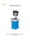
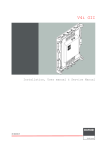
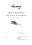
OPERATING INSTRUCTIONS
AR500
AR503
AR517
AR518
PROGRAMMABLE DIGITAL METERS
Version 1.2.2
2014.03.12
Thank you for choosing our product. These instructions will facilitate operating the device and
enable safe use of the controller at its full capacity. Prior to the installation and startup of the
device, please become familiar with these instructions. In the event of any additional questions,
please contact our technical adviser.
CONTENTS
1. SAFETY PRINCIPLES .................................................................................................................................... 3
3. GENERAL CHARACTERISTICS OF THE METERS ....................................................................................... 3
4. CONTENTS OF THE SET............................................................................................................................... 4
5. TECHNICAL DATA......................................................................................................................................... 4
6. ENCLOSURE DIMENSIONS AND INSTALLATION DATA .......................................................................... 5
7. DESCRIPTION OF TERMINAL STRIPS AND ELECTRICAL CONNECTIONS ............................................ 6
8. FUNCTIONS OF BUTTONS. MINIMUM AND MAXIMUM VIEW............................................................. 7
9. BINARY INPUT .............................................................................................................................................. 8
10. SETTING OF THE CONFIGURATION PARAMETERS .............................................................................. 8
11. QUICK ACCESS MENU ............................................................................................................................. 12
12. ANALOG OUTPUT AND ALARM CONFIGURATION ............................................................................ 12
12.1. CHANGING THE PRESET VALUE FOR THE ALARM AND THE MANUAL MODE ....................... 12
12.2. ANALOG OUTPUT ............................................................................................................................. 12
12.3. MANUAL AND REMOTE CONTROL FUNCTION ........................................................................... 12
13. MESSAGE AND ERROR SIGNALING ...................................................................................................... 13
14. CONNECTING THE CONTROLLER TO A COMPUTER AND AVAILABLE SOFTWARE....................... 13
15. RS485 COMMUNICATION INTERFACE (acc. to EIA RS-485) ............................................................. 14
16. MODBUS–RTU SERIAL TRANSMISSION PROTOCOL (SLAVE) .......................................................... 14
17. USER'S NOTES .......................................................................................................................................... 16
!
Please pay particular attention to the text marked with this sign.
The manufacturer reserves the right to make changes to the design and the programming of the device without any deterioration of the technical
parameters.
2
1. SAFETY PRINCIPLES
!
before you start to use the device, become familiar with the present instructions;
in order to avoid electrocution or damage to the device, its mechanical and electrical installation must be
performed by qualified staff;
before switching on the power supply, make sure that all cables and wires are properly connected;
before making any modifications to the wire and cable connections, switch off the device's power supply;
ensure proper operating conditions compliant with the technical specification of the device (power supply
voltage, humidity, temperature - see chapter 5).
2. INSTALLATION GUIDELINES
!
The device is designed so as to ensure an appropriate level of immunity to most interferences that may occur in
industrial environments. In environments of unknown level of interferences, it is recommended to implement the
following measures so as to prevent potential interference with the operation of the device:
do not supply the device from the same lines as high-power equipment without using appropriate power line
filters;
use cable shields on power supply cables, sensor cables, and signal cables, whereby the earthing of the shield
should be single-point and located as close to the device as possible;
avoid running instrument (signal) cables in the direct vicinity of and parallel to power distribution and power
supply cables;
it is recommended to use twisted pair signal cables;
in the case of sensing resistors in 3-wire connections, use identical wires;
avoid locating remotely controlled, electromagnetic meters, and high-power loads, loads with phase or group
power control, and other devices producing large impulse interferences close to one another;
ground or zero metal rails on which rail-mounted devices are installed.
Make sure to remove the protective film from the LED display before the first use of the device.
3. GENERAL CHARACTERISTICS OF THE METERS
measurement of temperature and other physical values (humidity, pressure, level, speed, etc.) processed to a
standard electrical signal (0/4÷20mA, 0÷10V, 0÷60mV, 0÷2,5kΩ);
1 universal measurement input (thermoresistance, thermocouple, and analog) with memory of the minimum
and maximum measured value and a remote data display function (over the MODBUS-RTU protocol); (except
for AR500)
programmable digital input (except for AR500) for changing the operation mode of the meter:
manual/automatic mode for the analog output, keypad block, stopping the display indications (HOLD
function)
analog output (except for AR500) 0/4÷20 mA or 0/2÷10 V (retransmission, alarm/control, manual)
manual mode for the analog output (open control loop) enabling setting the output signal value in the range
of 0-100% (except for AR500)
digital LED readout with programmable color (only AR517) and illumination brightness
signaling of alarm status with variable display color (only AR517)
integrated 24 V DC power supply supplying the field transducers (except for AR500)
RS485 serial interface (galvanically isolated, MODBUS-RTU protocol, except for AR500)
compensation of line resistance for resistance sensors and of temperature of cold thermocouple tips;
programmable type of input, range of indications (for analog inputs), alarm, display, communication, and
access options, and other configuration parameters
access to configuration parameters protected with a user password
parameter configuration methods:
3
−
from the film keypad located on the front panel (in AR500 and AR503 the buttons are accessible after the
front glass is taken out)
−
through the RS485 or the AR955 programmer and the ARSOFT-WZ1 free software (Windows
2000/XP/Vista/7/8)
software and the AR955 programmer that enables viewing the measured value and quick configuration single
or ready sets of parameters pre-saved on the computer in order to be used again, for example in other meters
of the same type (duplication of configuration)
panel enclosure (on the front side: IP65 - AR517, IP54 - AR500, AR503, AR518)
optionally (to be selected at the time of order): 24 V AC/DC power supply, analog output 0/2÷10 V and RS485
interface (does not apply to AR500)
high accuracy, long-term stability, and immunity to interferences;
available accessories:
−
AR955 programmer
−
RS485/USB converter
NOTE:
!
Before starting to work with the meter, you must become familiar with these operating instructions,
properly prepare the electrical system and the mechanical system, and correctly configure the parameters.
4. CONTENTS OF THE SET
a meter with grips for installation in a panel window
operating instructions
a warranty card
5. TECHNICAL DATA
1 universal input (set with parameter 0: inP )
measurement range
- Pt100 (RTD, 3- or 2-wire)
-200 ÷ 850
°C
- Ni100 (RTD, 3- or 2-wire)
-50
÷ 170
°C
- Pt500 (RTD, 3- or 2-wire)
-200 ÷ 620
°C
- Pt1000 (RTD, 3- or 2-wire)
-200 ÷ 520
°C
- thermocouple J (Fe-CuNi)
-40
÷ 800
°C
- thermocouple K (NiCr-NiAl)
-40
÷ 1,200
°C
- thermocouple S (PtRh 10-Pt)
-40
÷ 1,600
°C
- thermocouple B (PtRh30PtRh6)
300
÷ 1,800
°C
- thermocouple R (PtRh13-Pt)
-40
÷ 1,600
°C
- thermocouple T (Cu-CuNi)
-25
÷ 350
°C
- thermocouple E (NiCr-CuNi)
-25
÷ 820
°C
- thermocouple N (NiCrSi-NiSi)
-35
÷ 1,300
°C
- current
0/4
÷ 20
mA
- voltage (Rin = 110 kΩ )
0
÷ 10
V
- voltage (Rin > 2 M Ω)
0
÷ 60
mV
- resistance (3- or 2-wire)
0
÷ 2,500
Ω
- remote data display (through the RS485 or PRG port)
-1999 ÷ 9999
Response time (10 ÷ 90%)
0.25 ÷ 3 s (programmable with parameter 1: FiLt )
Resistance of leads (RTD, Ω)
Rd < 25 Ω (for each line)
Resistance input current (RTD, Ω)
400 μA (Pt100, Ni100), 200 μA (others)
(Rin = 50 Ω)
4
Processing errors (at ambient temperature of 25 °C):
- basic
- for RTD, mA, V, mV, Ω
0.1% of the measurement range ±1 digit
- for thermocouples
0.2% of the measurement range ±1 digit
- additional for thermocouples
<2 °C (temperature of cold tips)
- additional from ambient temperature changes
< 0.003% of the input range /°C
Resolution of measured temperature
programmable, 0.1 °C or 1 °C
Range of indications (resolution of analog inputs)
-1999 ÷ 9999, programmable
Position of the decimal point for analog inputs
programmable, 0 ÷ 0.000
Binary input (none in the AR500)
contact or voltage <24 V, bistable,
active level: short circuit or <0.8 V
Communication
interfaces
(RS485 and PRG, do not
use simultaneously)
-RS485 (galvanically separated),
option, none in the AR500
- speed 2.4 ÷ 115.2 kb/s,
- character format 8N1 (8 data bits, 1 stop bit, no
parity bits)
- PRG programming connection
- MODBUS-RTU protocol (SLAVE)
(no separation), standard
- current 0/4 ÷ 20 mA
Analog output
(standard)
(none in the AR500)
(1 current or voltage, not
- voltage 0/2 ÷ 10 V
separated from the input)
(option)
maximum resolution 1.4 μA (14 bit)
load capacity of the load Ro < 350 Ω
maximum resolution 0.7 mV (14 bit)
load capacity of the output Io < 3.7 mA (Ro > 2.7 kΩ)
- basic error of the output
< 0.1% of the output range
7-segment LED display - 4 digits
with programmable color (only AR517),
parameters 17: coLo , 18: AcoL ) and brightness (16: briG )
AR517 - 20 mm, 5 colors (red, dark- and brightorange, yellow, green), AR518 - 25 mm,
AR503 -14 mm, AR500 - 10 mm (blue), red
Signaling of alarms, messages, and errors
LED display, variable display color in AR517
Power supply (Usup)
- 230 VAC (standard)
85 ÷ 260 V AC/ 3 VA (none in the AR500)
- 24 VAC/DC (option)
20÷50 VAC/ 3 VA, 22÷72 VDC/ 3W, (standard in the AR500)
Power supply of field transducers (none in the AR500)
24 VDC / 30 mA
Rated operating conditions
0 ÷ 50 °C, <90% RH (no condensation)
Operating environment
air and neutral gases
Protection rating
- on the front side
IP65 - AR517, IP54 - AR500, AR503, AR518
- on the connections side
IP20
Weight
AR517 (approx.165 g), AR518 (approx.295 g),
AR500 (approx.60 g), AR503 (approx.100 g)
Electromagnetic compatibility (EMC)
immunity: according to the PN-EN 61000-6-2:2002(U)
standard
emissivity: according to the PN-EN 61000-6-4:2002(U)
standard
6. ENCLOSURE DIMENSIONS AND INSTALLATION DATA
a) AR517
Enclosure type
Material
Enclosure dimensions
Panel window
Fixing methods
Conductor
cross-sections
panel, Incabox XT L57
self-extinguishing NORYL 94V-0,
polycarbonate
96 x 48 x 79 mm
92 x 46 mm
grips on the side of the enclosure
2.5 mm2 (power supply), 1.5 mm2 (others)
5
b) AR518
Enclosure type
Material
Enclosure dimensions
Panel window
Protective cover IP54
Fixing methods
Conductor
cross-sections
c) AR500, AR503
Panel enclosure
Material
Enclosure dimensions
Panel window
Fixing methods
Conductor
cross-sections
panel, Incabox L57
self-extinguishing NORYL 94V-0
144 x 72 x 72 mm (W x H x D)
138 x 67 mm (W x H)
AR967 (option)
grips on the side of the enclosure
2.5 mm2 (power supply), 1.5 mm2
(others)
MULTIBOX - 482472 (AR500),
722408 (AR503)
self-extinguishing NORYL 94V-0
48x24x79 mm (AR500),
72x24x79 mm (AR503)
44x21 mm (AR500),
68x22 mm (AR503)
grips on the side of the enclosure
2.5 mm2 (power supply AR503),
1.5 mm2 (others)
7. DESCRIPTION OF TERMINAL STRIPS AND ELECTRICAL CONNECTIONS
Table 7. Numbering and description of terminal strips
Clamps
Description
1-2-3
input Pt100, Ni100, Pt500, Pt1000, resistance, (2- and 3-wire)
2-3
thermocouple input TC (J, K, S, B, R, T, E, N) and voltage input 0÷60 mV
3-5
current input 0/4÷20 mA
4-5
voltage input 0÷10 V
6 (none in the AR500)
output +24 V (in relation to the 5-GND) of the integrated power supply of field
transducers
5-7 (none in the AR500)
binary input (contact or voltage <24 V)
5-8 (none in the AR500)
analog current output (0/4÷20 mA) or voltage output (0/2÷10 V)
PRG
programming connection for cooperation with the programmer (only AR955)
9-10 (none in the AR500)
RS485 serial interface (MODBUS-RTU transmission protocol)
12-13
power supply input 230 VAC or 24 VAC/DC (in AR500 only 24 VAC/DC)
a) numbering of the connections on the back panel, method of connecting sensors and measurement signals and
the PRG adapter in AR500 and AR503 (description of terminal clamps - Table 7)
a.1) in AR517, AR518, AR503 (PRG item a.3)
a.2) in AR500 (PRG item a.3)
a.3) AR500, AR503
(PRG adapter connected)
NOTE: For connecting the device with a computer through the PRG socket, use only the AR955 programmer (for
AR500 and AR503 with an optional adapter). A connection made with a regular USB cable may cause damage to
6
the equipment. In AR500 and AR503, the PRG input is accessible from the top of the enclosure. Place the adapter
in the opening in the enclosure with the USB socket facing the nearest wall of the enclosure.
b) connection of a 2- and 3-wire transducer (Iout - output current, Uout - output voltage)
8. FUNCTIONS OF BUTTONS. MINIMUM AND MAXIMUM VIEW
a) Description of
the front side using
the example of
the AR517 device
b) AR500
a 7-segment LED display
programming buttons
c) AR503
In AR500 and AR503, the buttons are accessible after the front glass is removed.
a) button functions in the measurement display mode
Button
Description [and marking in the contents of the instructions]
[UP] or [DOWN]: changes the preset value for the alarm (parameter 6: SEt1 ) or the
analog output working in the manual mode 12: HSEt , see chapters 10 and 12.3
[SET] :
- output in the quick access menu (chapter 11)
[UP] and [DOWN] (at the same time): input in the parameter configuration menu (after
hold time longer than 1 s). If parameter 14: PPro = on (password protection is activated)
enter the access code (chapter 10)
[SET] and [UP] :
- displays the saved MAXIMUM VALUE of the measurement
- deletes the maximum value of the measurement (after hold time > 6 s)
[SET] and [DOWN] :
- displays the saved MINIMUM VALUE of the measurement
- deletes the minimum value of the measurement (after hold time > 6 s)
7
b) button functions in the parameter configuration menu and the quick access menu (chapters 10 and 11)
Button
Description [and marking in the contents of the instructions]
[SET] :
- edits the current parameter (the value blinks on the display)
- approves and saves the edited parameter value
[UP] or [DOWN]:
- moves to the next or previous parameter
- changes the value of the edited parameter
[UP] and [DOWN] (simultaneously):
- cancels the change of the edited value (and displays the parameter name again)
- returns to the measurement display mode (after hold time >0.5 s)
9. BINARY INPUT
Binary input BIN (not available in the AR500) performs a function that is programmable with parameter 15: Func
(chapter 10). The binary input works with the bi-stable signal i.e. the supplied signal (voltage or switch) must be
permanent (on/off type). Activation of the function is indicated by appropriate messages on the display (described
below).
Available BIN input functions
Source
Description (depending on the value of parameter 15: Func)
Func = nonE the BIN input is inactive (factory setting)
Message
-
Func = bLoc keypad block
bLoc / boFF
Func = hAnA unconditional manual mode for the analog output
hAnd / hoFF
Func = hoLd stopping the display indications (HOLD function)
hdoF / hoLd
10. SETTING OF THE CONFIGURATION PARAMETERS
All the controller's configuration parameters are saved in a non-volatile (permanent) internal memory.
When the device is switched on for the first time, an error message may be shown in the display due to the lack
of a sensor or the fact that the connected sensor is not factory-programmed. In such an event, the proper sensor
or analog signal must be connected and the configuration must be programmed.
There are two parameter configuration methods:
1. From the film keypad located on the front panel of the device:
(in AR500 and AR503, the buttons are accessible after the front glass is removed)
−
enter in the configuration menu from the mode where the input measurements are displayed (press the
[UP] and [DOWN] buttons simultaneously for more than 1 s) If parameter 14: PPro = on (password
protection is activated) then the display shows the message CodE , and then 0000 with the first digit
blinking, use buttons[UP] or [DOWN] to enter the password (default parameter 13: PASS = 1111 ), move
to successive positions or approve the code using the [SET] button
−
after entering the configuration menu (with message ConF ) the display shows the mnemonic name of the
parameter ( inP <-> FiLt <-> dot <-> etc.)
−
by pressing the [UP] button, one can move to the next parameter, and by pressing the [DOWN] button - to
the previous parameter (the list of the configuration parameters is presented in Table 10)
−
to change the value of the current parameter, press briefly the [SET] button (the parameter blinks in the
edition mode)
8
−
−
−
use buttons [UP] or [DOWN] to change the value of the edited parameter
approve the changed value of the parameter by pressing the[SET] button; cancel it by pressing the [UP]
and [DOWN] buttons (simultaneously and for a short moment); then parameter name is displayed again
to exit the configuration: press the [UP] and [DOWN] buttons for a long moment or wait approx. 2 minutes
2. Use the RS485 or the PRG port (AR955 programmer) and the ARSOFT-WZ1 software (chapter 14):
−
connect the meter to a computer port and start and configure the ARSOFT-WZ1 application
−
after the connection has been established, the current measured value is displayed in the window of the
software
−
setting and viewing of the device parameters is possible in the parameter configuration window
−
new parameter values must be approved with the Approve changes button
−
the current configuration can be saved in a file or set using values read from a file
−
a file with finished configuration can also be created using the ARSOFT-WZ4 software (chapter 14)
!
−
−
NOTE:
before disconnecting the device from a computer, press the Disconnect device button (ARSOFT-WZ1)
in the event of no response:
in the Program options check the configuration of the port and the MODBUS Address of the device
make sure that the serial port drivers in the computer have been properly installed for the RS485
converter or the AR955 programmer
disconnect for a few seconds and then reconnect the RS485 converter or the AR955 programmer
restart the computer
In the event of indications different than the actual value of the input signal, the zero and the sensitivity of a
sensor can be tuned: parameters 21: cALo (zero) and 22: cALG (sensitivity).
To restore the factory settings, when the power supply is switched on press buttons [UP] and [DOWN] and hold
them until the password menu appears ( CodE ), and then enter the following code 0112 .
As an alternative, a file with default configuration can be used in the ARSOFT-WZ1 software.
!
NOTE:
Do not perform configuration of the device with the keypad and through the serial interface (RS485 or AR955)
at the same time.
Table 10. List of configuration parameters
Parameter
0: inP
Type of measurement
input
Range of variability of the parameter and description
Pt
thermoresistance sensor (RTD) Pt100 (-200 ÷ 850°C)
ni
thermoresistance sensor (RTD) Ni100 (-50 ÷ 170°C)
Pt5
thermoresistance sensor (RTD) Pt500 (-200 ÷ 620°C)
Pt10
thermoresistance sensor (RTD) Pt1000 (-200 ÷ 520°C)
tc-J
thermoelectric sensor (thermocouple) type J (-40 ÷ 800°C)
tc-K
thermoelectric sensor (thermocouple) type K (-40 ÷ 1,200°C)
tc-S
thermoelectric sensor (thermocouple) type S (-40 ÷ 1,600°C)
tc-b
thermoelectric sensor (thermocouple) type B (-300 ÷ 1,800°C)
tc-r
thermoelectric sensor (thermocouple) type R (-40 ÷ 1,600°C)
tc-t
thermoelectric sensor (thermocouple) type T (-25 ÷ 350°C)
tc-E
thermoelectric sensor (thermocouple) type E (-25 ÷ 820°C)
tc-n
thermoelectric sensor (thermocouple) type N (-35÷ 1,300°C)
9
Factory
settings
Pt
1: FiLt filtration (1)
2: dot
position of the
point/resolution
3: Lo1 lower limit or
bottom of the indication
range (2)
4: Hi1 upper limit or
top of the indication range
4-20
current signal 4 ÷ 20 mA
0-20
current signal 0 ÷ 20 mA
0-10
voltage signal 0 ÷ 10 V
0-60
voltage signal 0 ÷ 60 mV
rES
resistance signal 0 ÷ 2,500 Ω
rEMo
remote input from the RS485 or PRG port, chapter 16, Table 16.6
1 ÷ 20
digital filtration of measurements (response time)
0
no point (2) or 1°C for temperature
1
0.0 (2) or resolution 0.1 °C for temperature
2
0.00 (2)
3
0.000 (2)
/999 ÷ 9999
indication 0/4 mA, 0 V, 0 Ω - start of the input scale (2)
/99.9 ÷ 1800
lower setting limit for the preset value of the alarm 6: Set1
/999 ÷ 9999
indication for 20 mA, 10 V, 60 mV, 2,500 Ω - end of the input
scale (2)
/99.9 ÷ 1800
upper setting limit for the preset value of the alarm 6: Set1
5
1
(0.1 °C)
/99.9 °C
850.0 °C
ALARM CONFIGURATION - chapter 12 (parameters insignificant to the AR500)
oFF
alarm constantly off
inu
reverse/heating
Figure 10.1. Characteristics of heating type alarm
5: out1 alarm type
oFF
dir
direct/cooling
Figure 10.2. Characteristics of cooling type alarm
bAon
in the band
Figure 10.3. Characteristics of alarm in the band
10
bAoF
outside of the
band
Figure 10.4. Characteristics of alarm outside of the band
6: SEt1 alarm value
changes in range 3: Lo1 ÷ 4: Hi1
7: H1 alarm hysteresis
0.0 ÷ 999.9 °C or 0 ÷ 9999 units (2)
100.0 °C
1.0 °C
ANALOG OUTPUT CONFIGURATION (chapter 12.2, parameters insignificant to the AR500)
0-20
mA
(0-10 V)
8: AtYP type of analog
output
depending on the order code: for current output 0-20 or 4-20 mA, for voltage
output 0-10 or 2-10 V
9: outA function of analog
output
oFF = off, hAnd = manual mode, rEtr = retransmission of measurement,
cont = alarm/control output, a detailed description is provided in chapter 12.2
oFF
10: A-Lo lower indication
for retransmission
start of the output scale - for output signal value 0/4 mA or 0/2 V (the parameter
is active only for measurement retransmission when 9: outA = rEtr )
0.0 °C
11: A-Hi upper indication
for retransmission
end of the output scale - for output signal value 20 mA or 10 V (the parameter is
active only for measurement retransmission when 9: outA = rEtr )
100.0 °C
12: HSEt preset value of
the manual mode
0 ÷ 100 %
1% step
control value for the analog output operating in the manual
mode, chapters 12.2 and 12.3
50 %
ACCESS, DISPLAY, AND COMMUNICATION OPTIONS AND OTHER CONFIGURATION PARAMETERS
13: PASS password
0000 ÷ 9999
password for the parameter configuration menu
14: PPro protection of the
configuration with a
password
oFF
entry into the configuration menu is not password-protected
on
entry into the configuration menu is password-protected
15: Func
the BIN input function
(chapter 9, parameter
insignificant to the AR500)
16: briG illumination
brightness
17: coLo basic color
18: AcoL alarm color
19: AddrMODBUS-RTU
address
20: br
speed for RS485
nonE
the BIN input is inactive
bLoc
keypad block
hAnA
unconditional manual mode for the analog output
hoLd
stopping the display indications (HOLD function)
50 ÷ 100 %
brightness of the display, a 50% increase
1111
on
nonE
100 %
GrEE = green, YELL = yellow, orAn = orange,
AMbE = amber, rEd = red, coLo = basic (only for 18: AcoL )
(18: AcoL - display color for connected alarm) (3)
1 ÷ 247
individual address of the device in the RS485 network
(chapter 16)
2.4 kbit/s
4.8 kbit/s
9.6 kbit/s
38.4 kbit/s
57.6 kbit/s
115.2 kbit/s
19.2 kbit/s
21: cALo calibration
of the zero
zero offset for measurements: -50.0 ÷ 50.0 °C or -500 ÷ 500 units (2)
22: cALG gain
85.0 ÷ 115.0 % Slope calibration (sensitivity) for measurements
rEd
AcoL
1
19.2
kbit/s
0.0 °C
100.0 %
Notes: (1) – for FiLt = 1 the response time is equal to 0.25 s, for FiLt = 20 it is equal to at least 3 s. A higher
degree of filtration means a more "smooth" measured value and a longer response time,
11
which is recommended in the case of turbulent measurements (e.g. water temperature in a boiler)
(2) – applies to analog inputs ( mA, V, mV, Ω )
(3) – a non-significant parameter for AR500, AR503, and AR518 (as the display is a single-color one)
11. QUICK ACCESS MENU
In the measurement mode (when the measured value is displayed), it is possible to immediately access certain
parameters without the need to enter a password. This possibility is offered by the quick menu, which can be
accessed by pressing the [SET] button. The parameter is selected and edited in the same way as described above
(in chapter 10).
Table 11. List of elements accessible in the quick configuration menu.
Element Description
SEt1
preset alarm value (parameter 6: SEt1 ), optional element - unavailable when parameter 5: out1 = oFF
HSEt
preset value of the manual mode (12: HSEt ), optional element - available in the manual operation mode
12. ANALOG OUTPUT AND ALARM CONFIGURATION
The programmable architecture of the meter enables using it in many fields and applications. Before the operation
of the device starts, it is necessary to set the parameters according to specific requirements (chapter 10).
A detailed description of configuration of the operation of the analog output and the alarm is given in chapters
12.1÷ 12.3. The alarm can be signaled both through the analog output (not available in the AR500) and through
variable color of the display (parameter 18: AcoL only in the AR517). The default (factory) configuration
is the following: the analog output and the alarm are switched off (Table 10, Factory settings column).
12.1. CHANGING THE PRESET VALUE FOR THE ALARM AND THE MANUAL MODE
In the measurement mode, the display shows the value being measured. The simplest way to change the preset
value for the alarm or the manual mode (parameter 6: SEt1 or 12: HSEt when the analog output is in the manual
mode) is to use the [UP] button or the [DOWN] button. As an alternative, it is possible to change the preset value
in the parameter configuration mode (using the methods described in chapter 10).
12.2. ANALOG OUTPUT
The standard of the output signal is determined by parameter 8: AtYP (chapter 10, table 10). The analog output
can work in one of the following modes: retransmission of measurement (parameter 9: outA = rEtr ), manual
mode (9: outA = hAnd ) and as an alarm/control output (9: outA = ALAr ).
In the measurement retransmission mode, the output signal is proportional to the measured signal in the range
set by parameters 10: A-Lo and 11: A-Hi (e.g. 0 mA for the measured value 0 °C when A-Lo = 0 °C, 20 mA for 100 °C
when A-Hi = 100 °C and, as appropriate, 10 mA for the half of the range, i.e. 50 °C).
Manual operation (chapter 12.3) makes it possible to change the output signal in the range of 0 ÷ 100%
with a 1% step.
In the alarm/control output mode, the alarm/control parameters are mandatory
(the following apply: 5: ovt1 , 6: SEt1 , 7: H1 ). In the alarm/control mode, the range of variability of the analog
signal is not continuous and the output assumes limit values (lower or upper, e.g. 0 mA or 20 mA), without
intermediate values. The analog output is not available in the AR500.
12.3. MANUAL AND REMOTE CONTROL FUNCTION
The manual mode enables setting the value of the output signal in the entire range of its variability (0-100%), thus
enabling operation in an open regulation loop (no automatic coupling between the measured value and the
12
output signal). Manual operation is available for the analog output of the meter and is programmed using
parameters 9: outA , chapter 10, Table 10. Also, the output can be configured for quick (unconditional) manual
mode controlled by the BIN binary input, by programming parameter 15: Func for the value hAnA (chapter 9).
The preset value of the manual mode (parameter 12: HSEt ) can be set directly using the [UP] or [DOWN] button or
using the quick menu (chapter 11), or alternatively, in the parameter configuration mode (from the film keypad of
the meter or remotely using the RS485 or PRG serial port, chapters 10, 14 ÷ 16 ).
13. MESSAGE AND ERROR SIGNALING
a) measurement errors:
Code
Possible causes of error
^^^^
____
- the measurement range of the sensor is exceeded from the top ( ^^^^ ) or from the bottom ( ____ )
- the sensor is broken
- the sensor that is connected is different than the one that is set in the configuration
(chapter 10, parameter 0: inP )
b) temporary messages and errors (one-time and recurring):
Code
Description of message
CodE
mode of entering the password for access to the configuration parameters, chapter 10
Err
the password is invalid
ConF
access to the parameter configuration menu
bLoc / boFF
keypad block on/off, chapter 9
hAnd / hoFF
unconditional manual mode on/off, chapter 9
hoLd / hdoF
stopping of display indications (HOLD function) on/off, chapter 9
SAUE
saving of factory parameter values (chapter 10)
14. CONNECTING THE CONTROLLER TO A COMPUTER AND AVAILABLE SOFTWARE
It may be useful (or necessary) to connect the meter to a computer in the following situations:
- remote monitoring and recording of current measurement data and control of the status of the analog output
- quick configuration of parameters, to include copying of settings to other meters of the same type
In order to establish communication over long distances, it is necessary to establish a connection in the RS485
standard with an available port in the computer (directly or using an RS485 converter), as described in chapter 15.
Moreover, as a standard, the meters are equipped with a PRG port which enables connecting to a computer using
an AR955 programmer (without galvanic separation, cable length approx. 1.2 m). Both the programmer and the
RS485 converter require installation of the supplied serial port drivers on the computer.
Communication with devices is effected using a protocol compatible with MODBUS-RTU (chapter 16).
The following applications are available (on a CD supplied with the AR955 programmer or to be downloaded from
the Internet at www.apar.pl, Download section, for operating systems Windows 2000/XP/Vista/7/8):
Name
Software description
ARSOFT-WZ1
(free)
- display of current measurement data from the connected device
- configuration of the type of measurement input, the indication range, the alarm options
display communication, and access options, etc. (chapter 10)
- creation of a disk with a "cfg" extension, containing the current configuration
of the parameters to be used again (duplication of configuration)
- the program requires communication with the meter via the RS485 or PRG (AR955) port
13
ARSOFT-WZ4
(free)
- creation on the disk of a ready configuration file with a "cfg" extension
enabling programming the meter in the future using
the RS485 interface or the AR955 and ARSOFT-WZ1 programmer
- the program does not use communication with the meter
ARSOFT-WZ2
(payable)
- display and recording of current measurement data from a maximum of 30 channels
at the same time (only from devices made by APAR)
- the program requires communication with the meter via the RS485 or PRG (AR955) port
The detailed descriptions of the aforementioned applications can be found in the installation folders.
!
NOTE:
Before establishing the connection, make sure that the MODBUS address of the device (parameter 19: Addr ) and
the speed of transmission (20: br ) are the same as the settings of the software. Moreover, in the software, set the
number of the COM serial port in use (in the case of the RS485 converter or the AR955 programmer it is the
number assigned by the operating system during installation of the drivers).
15. RS485 COMMUNICATION INTERFACE (acc. to EIA RS-485)
Max. RS485 cable length – 1 km. Max. no. of devices
in the RS485 line – 30 – in order to increase the number, use
RS485/RS485 amplifiers. Termination resistors when the MASTER
is at the start of the line (fig. above):
- at the start of the line – 2 x 820 Ω to the ground and +5 V MASTER and 150 Ω between the lines;
- at the end of the line – 150 Ω between the lines.
Termination resistors when the MASTER is in the middle of the line:
- at the converter – 2 x 820 Ω to the ground and +5 V converter;
- at both ends of the line – 150 Ω each between the lines.
16. MODBUS–RTU SERIAL TRANSMISSION PROTOCOL (SLAVE)
Character format: 8 bits, 1 stop bit, no parity bit
Available functions: READ - 3 or 4, WRITE - 6
Table 16.1. Claim frame format for the READ function (frame length - 8 bytes):
address of the
device
function
4 or 3
read register address:
0 ÷ 39 (0x0027)
number of read registers:
1 ÷ 40 (0x0028)
CRC check sum
1 byte
1 byte
2 bytes (HB-LB)
2 bytes (HB-LB)
2 bytes (LB-HB)
Example 16.1. Reading of a register with address 0: 0x01 - 0x04 - 0x0000 - 0x0001 - 0x31CA
Table 16.2. Claim frame format for the WRITE function (frame length - 8 bytes):
address of the
device
function 6
write register address:
0 ÷ 39 (0x0027)
write register value
1 byte
1 byte
2 bytes (HB-LB)
2 bytes (HB-LB)
CRC check sum
2 bytes (LB-HB)
Example 16.2. Entry in a register with address 10 (0xA) with the 0 value: 0x01 - 0x06 - 0x000A - 0x0000 - 0xA9C8
14
Table 16.3. Response frame format for the READ function (minimum frame length - 7 bytes):
address of
the device
number of bytes in the
data field (max. 40*2=80
bytes)
function
4 or 3
data field - register value
CRC check sum
1 byte
1 byte
1 byte
2 ÷ 80 bytes (HB-LB)
2 bytes (LB-HB)
Example 16.3. Response frame for register value equal to 0: 0x01 - 0x04 - 0x02 - 0x0000 - 0xB930
Table 16.4. Response frame format for the WRITE function (frame length - 8 bytes):
copy of the claim frame for the WRITE function (Table 16.2)
Table 16.5. Special response (errors: function field = 0x84 or 0x83 in the case of the READ function and 0x86 in
the case of the WRITE function):
Error code (HB-LB in the data field)
Error description
0x0001
non-existing register address
0x0002
wrong write register value
0x0003
improper function number
Example 16.5. Error frame for a non-existing read register address: 0x01 - 0x84 - 0x02 - 0x0001- 0x5130
Table 16.6. Map of registers for the MODBUS-RTU protocol
Register
address
HEX (DEC)
0x00 (0)
Value
(HEX or DEC)
-1999 ÷ 19999
current measurement value
-1999 ÷ 9999
value to be displayed for the remote input (when parameter 0: inP = rEMo)
0x01 (1)
517
0x02 (2)
100 ÷ 999
0x03 ÷ 0x05
Description of register and access type
(R- read only register, R/W - read and write register)
0
0x06 (6)
0÷1
0x07 (7)
R/W
device type identifier
R
meter software (firmware) version
R
not used or reserved
R
current alarm status: bit0, bit0=1 means that the alarm is on
R
0 ÷ 20000
current state of the analog output (0 ÷ 20000 μA or 0 ÷ 10000 mV)
R
0x08 (8)
-100 ÷ 700
thermocouple cold tip temperature (resolution 0.1°C )
R
0x09 (9)
-1999 ÷ 19999
minimum measurement value
R
0x0A (10)
-1999 ÷ 19999
maximum measurement value
R
not used or reserved
R
0x0B ÷ 0x10
0
Configuration parameters (chapter 10)
0x11 (17)
0 ÷ 17
parameter 0: inP type of measurement input (chapter 10)
0x12 (18)
1 ÷ 20
parameter 1: FiLt digital filtration of measurements (response time)
R/W
0x13 (19)
0÷3
parameter 2: dot position of the point or resolution for temperature
R/W
0x14 (20)
-1999 ÷ 18000
parameter 3: Lo1 lower limit for the alarm or bottom of the indication range
R/W
0x15 (21)
-1999 ÷ 18000
parameter 4: Hi1 upper limit for the alarm or top of the indication range
R/W
0x16 (22)
0÷4
parameter 5: out1 alarm type
R/W
0x17 (23)
-1999 ÷ 18000
parameter 6: SEt1 preset value for the alarm
R/W
0x18 (24)
0 ÷ 9999
parameter 7: H1 alarm hysteresis
R/W
0x19 (25)
0÷1
Parameter 8: AtYP type of analog output
R/W
0x1A (26)
0÷3
parameter 9: outA function of analog output
R/W
0x1B (27)
-1999 ÷ 18000
parameter 10: A-Lo lower indication for retransmission
R/W
0x1C (28)
-1999 ÷ 18000
parameter 11: A-Hi upper indication for retransmission
R/W
15
R/W
0x1D (29)
0 ÷ 100
parameter 12: HSEt preset value of the manual mode
R/W
0x1E (30)
0 ÷ 9999
parameter 13: PASS password
R/W
0x1F (31)
1÷2
parameter 14: PPro protection of the configuration with a password
R/W
0x20 (32)
0 ÷3
parameter 15: FuncBIN input function
R/W
0x21 (33)
20 ÷ 100
parameter 16: briG brightness of the display, a 50% increase
R/W
0x22 (34)
0 ÷4
parameter 17: coLo basic color of the display
R/W
0x23 (35)
0 ÷5
parameter 18: AcoL alarm color of the display
R/W
0x24 (36)
1 ÷ 247
parameter 19: Addr MODBUS-RTU address in the RS485 network
R/W
0x25 (37)
0÷6
0x26 (38)
0x27 (39)
parameter 20: br speed for RS485
R/W
-500 ÷ 500
parameter 21: cALo zero offset for measurements
R/W
850 ÷ 1150
parameter 22: cALG Slope calibration (sensitivity) for measurements
R/W
17. USER'S NOTES
16