1
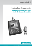
PowAirBox 12V/24V/230V
Supply system for power and compressed air with automatic ejection
User Manual
V 1.0
www.leab.eu
1
Important information about this documentation
The technical data, information and illustrations have been put together
carefully and correspond to the production status at the time the documentation
was prepared.
However, the manufacturer retains the right to improve or modify the
products, specifications and documentation without notice at any time according
to technical requirements and the latest development status.
The descriptions have been prepared in detail and with great care. Nevertheless,
errors can never be ruled out entirely. No liability will be accepted for errors of
damage which could originate from these or from faulty interpretations.
The contents of this documentation may not be copied, reproduced, translated
or forwarded to third parties in any other way without the express permission of
LEAB Automotive GmbH .
!
Caution!
Safety note, non-observance can lead to personal injury or material
damage as well as impair the device function.
Caution! Hazard through electric voltage
Safety note, non-observance can lead to injuries and death as well as
damage or destroy the device.
i
Note
Supplementary information on how to handle the device.
Important note on using the device
To avoid operational errors, you should read this manual carefully before
installation and before initial use, and always follow the respective instructions.
Please keep this manual near the device for future reference so that operators can
use it to find out about the device‘s functions.
2
Contents
Important note on using the device . . . . . . . . . . . . . . . . . . . . . . . . . . . . . . . . . . . . 2
1 . Scope of supply . . . . . . . . . . . . . . . . . . . . . . . . . . . . . . . . . . . . . . . . . . . . . . . . . 4
2. Performance characteristics and operating functions . . . . . . . . . . . . . . . . . . 5
3. Installations and assembly . . . . . . . . . . . . . . . . . . . . . . . . . . . . . . . . . . . . . . . . 6
Installation spot . . . . . . . . . . . . . . . . . . . . . . . . . . . . . . . . . . . . . . . . . . . . . . . . . . . . 6
Installation . . . . . . . . . . . . . . . . . . . . . . . . . . . . . . . . . . . . . . . . . . . . . . . . . . . . . . . . 6
Connection of power and compressed air . . . . . . . . . . . . . . . . . . . . . . . . . . . . . . . 7
Completion . . . . . . . . . . . . . . . . . . . . . . . . . . . . . . . . . . . . . . . . . . . . . . . . . . . . . . . . 8
Installation of the ceiling device (optional) . . . . . . . . . . . . . . . . . . . . . . . . . . . . . . 9
Coupling connection . . . . . . . . . . . . . . . . . . . . . . . . . . . . . . . . . . . . . . . . . . . . . . . . . 9
4 .Operation . . . . . . . . . . . . . . . . . . . . . . . . . . . . . . . . . . . . . . . . . . . . . . . . . . . . . 10
5. Troubleshooting . . . . . . . . . . . . . . . . . . . . . . . . . . . . . . . . . . . . . . . . . . . . . . . . 10
6. Maintenance and service . . . . . . . . . . . . . . . . . . . . . . . . . . . . . . . . . . . . . . . . . 11
7. Warranty conditions . . . . . . . . . . . . . . . . . . . . . . . . . . . . . . . . . . . . . . . . . . . . 12
8. Spare parts, accessories . . . . . . . . . . . . . . . . . . . . . . . . . . . . . . . . . . . . . . . . . . 13
9. Dimensional drawing . . . . . . . . . . . . . . . . . . . . . . . . . . . . . . . . . . . . . . . . . . . . 14
10. Technical data . . . . . . . . . . . . . . . . . . . . . . . . . . . . . . . . . . . . . . . . . . . . . . . . . . 15
11. CE Declaration of Conformity . . . . . . . . . . . . . . . . . . . . . . . . . . . . . . . . . . . . . . 15
3
1. Scope of supply
With the LEAB PowAirBox 12V/24V/230V you have purchased a high-quality power
and compressed air supply system for emergency vehicles. Please check before use
whether the following items are included in the scope of supply:
• PowAirBox charging station type A (with compressed air supply)*
or B (without compressed air supply)*
• PowAirBox coupling with 4 m cable
• Connection cable A for charging station, plug&play, length 4 m
• Connection cable B for charging station, plug&play, length 4 m
• Connection cable C for charging station, plug&play, length 4 m
• Connection cable output 12/24V (2-wire) or 230V (3-wire) for charging station,
plug&play, length 4 m
• Connection hose for compressed air, length 4 m,
(only for version A for compressed air)
• Mounting frame for PowAirBox charging station
• Attachment screws, hexagon socket A2 black M4x25, 6 pcs.
• English manual (this document)
*
optional
**
further cable lengths on request
If the scope of supply does not correspond to these items, or the PowAirBox,
coupling or connection cable are damaged, please contact your dealer or LEAB
directly.
If you should require an additional manual, you can download this in PDF
format from www.leab.eu free of charge, or access our product page directly by
smartphone:
If you should require spare parts or accessories for your LEAB PowAirBox, please
see section 8 of this manual and send your order by email to [email protected].
4
2. Performance characteristics and operating functions
The LEAB PowAirBox is a system which supplies both electrical power and
compressed air to emergency vehicles by using a special coupling and multi-cable.
The coupling is automatically disconnected from the vehicle when the vehicle
engine is started, the protective cover closes automatically.
The battery indicator (standard feature) provides reliable information about the
current state of charge of the vehicle battery as well as the charging process.
Two auxiliary contacts in the PowAirBox can be freely assigned and used either for
signal transmission or to establish start prevention as required.
There are two systems available:
• PowAirBox type A
for supplying power and compressed air at the same time
• PowAirBox type B for supplying power
Each of these systems is available either for 12, 24 or for 230V
supply. Coded pins prevent plugs and couplings of different
voltages being mixed up.
Systems with and without compressed air are 100% compatible
and can also be inserted mixed alternately. In this case, there is no air supply but
no loss of air either.
PowAirBox charging station and coupling are delivered with 4m connection cable
each in the standard version. Other lengths are available on request.
Connection in the vehicle is by means of lockable IP68 plug contacts.
We recommend the use of the PowAirBox in connection with the built-in battery
chargers of the series LEAB ABC, LEAB CPC and LEAB Champ.
Ceiling device (with or without charger)
Combined cable 230V & compressed air
Power distributor 230V
Compressed air
Compressor 8-10 bar
Energy distribution at the station
(power & compressed air)
PowAirBox supply
5
3. Installation and assembly
!
When selecting the installation location, the installation process itself
and electrical connection to the on-board power supply, observe the
specifications in the vehicle body manufacturer‘s manual and general
technical regulations.
Electrical work on cables and consumers and the connection set-up
should only be carried out by appropriately authorised electrical
specialists.
Installation spot
The PowAirBox must be installed on a vertical surface to guarantee perfect
function. Ideal installation locations are near the driver door or on the rear of the
vehicle. Make sure there is sufficient installation space available. This particularly
applies to the necessary installation depth of 121 mm.
The PowAirBox cover can be opened to the left or right, space requirements must
be checked here, too.
Installation
The PowAirBox is delivered with the mounting frame already
mounted, this serves as an installation template at the same
time.
Loosen the 6 black screws (hexagon socket 2.5 mm) and
remove the mounting frame.
Place the mounting frame in the installation position on the
surface of the vehicle and mark the inner contour of the frame
and the 6 screw holes.
The rubber seal is already glued to the back of the mounting frame.
i
6
Do not remove the protective film from the adhesive tape yet
Cut or nick the marked inner area out and drill the
marked holes using a drill size 4.5 to 5 mm.
The mounting frame is made of stainless steel and
has 6 press-in nuts. Screw the 6 x 4 mm threaded pins
provided into the nuts by hand from the smooth side.
Check whether the mounting frame fits the cut-out from
the inside and whether the threaded pins fit easily
through the drilled holes.
!
Seal the cut surfaces and drilled holes with zinc primer or similar to
avoid corrosion later.
Once you have made sure that everything fits, pull the protective film off the
rubber seal and glue the frame into the cut-out from the inside.
The threaded pins can now be removed, they are no longer required.
Connection of power and compressed air
We recommend routing the connection cables provided and the compressed air
hose in the vehicle and connecting this to the on-board voltage and the 230 V
on-board installation before final installation of the PowAirBox charging station.
Then connection to the PowAirBox should be made via the cable screw
connections.
!
i
Terminal A: The start signal for the ejector magnet should ideally be
provided via terminal 50 (starter control). Do not connect permanent
plus. This could destroy the ejector magnet.
Note the specifications of the vehicle body manufacturer‘s manual when
connecting the air line.
If you connect permanent voltage to terminal B, the current battery
voltage will always be displayed.
7
Completion
Once all the cables have been routed properly in the vehicle and connected
correctly, connect the plugs to the respective terminals on the PowAirBox charging
station.
When inserting the plugs, turn them slightly to the left and right until the guide
engages and then tighten the sealing cap by hand.
Terminal B
2-wired cable to permanent voltage (Battery indicator),
brown = +, blue = -;
Terminal A
Terminal C
2-wired cable to starter
(clamp 50), brown = +, blue = Do not connect
permanent voltage!
Connection to 2 auxiliary
contacts, contacts are
bridged in the coupling and
be used for indication or
start prevention.
Compressed air hose
Hose 6 mm is mounted
only with type PowAirBox A.
Output 12/24 or 230V
Depending on the type 2 or 3-pin connector:
2-pol (12/24 V) plus (pin 1)/minus (pin 2) to battery (2x 4 mm²).
3-pol (230 V) 3-wires to 230 V-cabinet (3x 2.5 mm²)
LEAB charger can come with appropriate plug ready to run – plug & go.
!
i
Do not use any tools when screwing the plugs into the terminals in
order to avoid damage to the plugs or thread.
Assign plugs and terminals correctly and do not mix them up in order to
guarantee correct function.
We recommend occupying the central terminal (B) first to make installation easier.
Once all the cables (and compressed air pipe if appropriate) have been connected
to the charging station, push the PowAirBox into the cut-out.
Carefully insert the 6 hexagon socket screws and tighten them evenly until the
rubber seal is flush cleanly all the
way round.
Do not use an electric or
Use medium-strength threadlocker
pneumatic screwdriver to
to avoid unintentional loosening at
tighten the M4 screws.
a later date.
!
8
Installation of the ceiling device (optional)
We recommend the optional ceiling device (see accessories, Chapter 8) for
trouble-free operation.
Ceiling device with multi-cable
Stainless steel mounting frame
PA cover
Mount the mounting frame on the ceiling at a distance of about 30 cm away from
the side of the vehicle.
If the distance is not large enough, the cable will swing back after ejection and
could get caught in the vehicle body.
If the distance is too large, the cable could swing too far from the vehicle and could
touch the vehicle parked next to it.
The length of the cable must be dimensioned in such a way that the coupling
does not touch the floor. A distance of 60 to 80 cm is usually ideal. This avoids
mechanical damage to the coupling and contact with the wet depot floor.
Coupling connection
When connecting the cable to the coupling, assign the wires as follows:
Function
Combined cable power/compressed air
Electric cable H07-BQ
PE
green/yellow
green/yellow
L
1
brown
N
2
blue
Auxiliary contact 1
3
black
Auxiliary contact 2
4
grey
Both auxiliary contacts are bridged in the coupling to show the message “mains connected”
to the vehicle. If you want to use the auxiliary contacts for transmitting data to or from the
vehicle the auxiliary contacts in the coupling must be connected according to the table
above.
!
The PowAirBox cable must not be used together with balancers, cable
winders or similar. These systems might lead to the coupling in the
PowAirBox becoming jammed and not being ejected, and consequently
to a lapse of warranty.
9
Pow
A
4. Operation
irB
ox
The battery display on the charging box
indicates the current state of the battery
connected.
Insert the PowAirBox coupling into the
PowAirBox charging box. To do this, use
your thumb to turn the box cover up to
the side, the cover will pivot away and
reveal the plug contacts. Insert the
coupling into the charging box until you
can feel and hear it „click in place“.
The coupling is actually held in place by a
particularly strong magnet.
The vehicle‘s batteries are now charged, which is signalised by a circulating and
flashing display.
Start the vehicle engine to eject the coupling automatically and interrupt the
power and compressed air supply.
5. Troubleshooting
If your PowAirBox is not working as it should, please try to localise the fault using
the following procedure first.
Fault
Coupling is not ejected
Battery display not shown
Cause
Remedy
Has the starter been pressed?
Press the starter
Power at terminal 50?
Measure the voltage at terminal 50
Coupling jammed?
Has a cable winder been used?
Battery connected?
Check terminal B connection
Check FI or LS in the depot
Charger not charging
230V voltage at the coupling?
Check the supply cable
Check FI or LS in the vehicle
If this is not successful, please contact your specialist dealer or LEAB. Have the
serial number and date of purchase on hand as well as an accurate description of
the fault so that we can help you as quickly as possible.
10
6. Maintenance and service
Regular tests
Check the PowAirBox regularly before every use as follows:
• Supply cable and coupling undamaged?
• Charging station undamaged?
• Supply cable fixed securely to the ceiling?
• Have the coupling and cables been in contact with water, oil or other fluids?
When used commercially, the LEAB PowAirBox is part of an electrical installation in
the sense of the German accident prevention regulation BGV-A3.
This employers‘ liability association regulation prescribes the regular testing
of devices for electrical safety (usually once a year). Please clarify with your
employers‘ liability association whether you are affected by this or any
comparable regulation and take the measures necessary for the safety of your
employees.
Your employers‘ liability association or work accident insurance company will be
able to provide more information.
!
Clean the coupling and charging box cable regularly to guarantee
perfect function and detect any damage immediately.
Protect the coupling and cable from being driven over by vehicles,
other mechanical damage and wet conditions.
Protect the cable from damage by sharp-edged vehicle or building
parts.
Do not use the pivoted cover of the PowAirBox to hang cables or
jackets on.
Check regularly that the screws are tight.
Have regular checks done in accordance with accident prevention
regulation BGV-A3.
Do not used a damaged PowAirBox or parts of one again.
Replace faulty parts or damaged cables without delay.
Only use the PowAirBox for the voltages given.
Always have any necessary repairs done exclusively by LEAB.
Always make sure the device is voltage-free before starting work.
i
Spare parts can be purchased from your specialist dealer or from
LEAB directly
11
7. Warranty conditions
Providing installation has been carried out professionally and the devices are
used according to their intended purpose, LEAB offers mandatory warranty over a
period of 36 months after the date of purchase.
If any defects of faulty functions should occur during this period under normal
conditions of use, LEAB will either repair the device free of charge or replace it at
their own discretion. New or repaired parts of equal value can be used for
replacement.
A warranty claim cannot be recognised under the following circumstances:
• The device was not used in accordance with the recommendations
given in this manual.
• The device was used for purposes other than general automotive, solar,
industrial or maritime applications without prior agreement with LEAB.
• The device was repaired or modified without express permission from LEAB.
• The device shows signs of damage caused by overload, penetration of
humidity (water, oil, acid), mechanical force, excess or insufficient voltage
or any other non-intended use.
Pre-conditions for warranty payments
Warranty claims can be made to your specialist dealer or LEAB directly.
The following documents are required:
• Invoice or delivery note
• Model description or type
• Serial number
• Detailed description of the fault and installation, if appropriate
Procedure
If the device cannot be put back into operation perfectly according to the
instructions in this manual or if the fault persists, contact your dealer‘s Service
department or LEAB directly.
If this is no help either, please request a processing form and processing number
(RMA number) as well as a free UPS pick-up sticker (free UPS pick-up service
unfortunately only possible in Germany) by calling +49 (0)4621 - 97860-120 or
sending a mail to [email protected]. You can send the defective device to us
together with these documents free of charge. We will then examine it and repair
it if necessary.
12
8. Spare parts, accessories
The following accessories can be ordered from LEAB Service at bestellung@leab.
eu or in the LEAB shop at http://shop.leab.eu under specification of the article
number:
Pos.
Description
Article number
Ceiling device
PowAirBox ceiling device with stainless steel holder
1549000000
Supply adapter
PowAirBox adapter Schuko → PowAirBox 5.0 m
1549230022
Mounting frame
PowAirBox mounting frame VA
9970360000
Installation seal
PowAirBox seal for installation
9970250002
Champ 1230 Pro
Battery charger Champ 1230 Pro
0101043890
Champ 2420 Pro
Battery charger Champ 2420 Pro
0101043891
CPC 1230
Battery charger CPC 1230, J117C
0101036930
CPC 2430
Battery charger CPC 2430, J114C
0101036931
CTS-5
Combined sensor cable (voltage + temperature)
for CPC battery chargers 5.0 m
1601035598
CTS-10
Combined sensor cable (voltage + temperature)
for CPC battery chargers 10.0 m
1601035595
Inquiries for spare parts can be made by calling +49-4621-9780-110 or sending an
email to [email protected].
13
9. Dimensional drawing
145
193
163
193
121,5
79
110
Alle Angaben in mm.
14
10. Technical data
Supply voltage
Choice of 12 V, 24 V or 230 V
Rated current
20 A
Compressed air
Max. 13 bar
Contacts (standard)
5-pole, of which 2 are auxiliary contacts
Display
Battery state of charge, charge control, undervoltage
alarm
On-board voltage
Universal 12 and 24 VDC
Lifting magnet
Universal 12 and 24 VDC
Material
Glass-fibre reinforced polyamide
Dimensions
See drawing
Weight (charging station)
1.2 kg (without cable)
Type of protection
IP55
Weight (coupling)
1.14 kg (with 4 m multi-cable)
Length of connection cable
(charging station and coupling)
4 m (standard), other lengths on request
Warranty
36 months
11. CE Declaration of Conformity
The product
LEAB PowAirBox 12V/24V/230V
with/without compressed air supply
complies with the requirements of the directives 2011/65/EU of the
European Parliament and Council dated 8th June 2011 restricting the use of certain
hazardous substances in electrical and electronic devices.
The following EU directives were applied:
2006/95/EC, 2004/104/EC and Low Voltage Directive 72/245/EEC.
Busdorf, 31.01.2014
Bart Westerkamp
Managing Director
15
www.leab.eu
LEAB Automotive GmbH
Thorshammer 6
24886 Busdorf
Germany
T +49 (0) 46 21 97 860-110
F +49 (0) 46 21 97 860-260
[email protected]
16