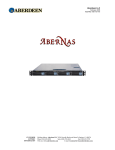
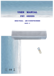
1
Multi Variable Air Conditioners
Ducted Type Indoor Unit Owner’s Manual
Models
:
OV-R224P/Na-M
OV-R280P/Na-M
Please read this manual carefully before operating
Thank you for choosing ONIDA Air Conditioner Units, please read this manual carefully
before using this unit and operates it correctly according to guideline in this manual, and
1
Safety Precautions
3
The selection of installation place and notice of the air conditioner
unit
4
Install the ducted type indoor unit
6
Name and Function of Each Part of Ducked Type Indoor Unit
20
Working Temperature Range
21
Wired remote control operation procedure
User notices
Remote controller
operation procedure
CONTENTS
keeps it for reference.
The components of the wired remote control
22
On/Off operation
22
Timer setting
23
SLEEP mode setting
24
Fan Speed Control
24
Temp. adjusting
25
Set of running mode
25
Malfunction display
25
Names and functions of every button of the remote control
27
Names and functions of every button of the remote control
(Remove the cover)
28
Operation procedure
29
How to insert batteries
29
Trouble shooting
30
Care and maintenance
31
Performance parameters list of the ducted type indoor unit
32
USER NOTICES
☆
When the unit is operating, the total capacity of the indoor units should be no more than the
capacity of outdoor unit. Otherwise, it can cause the shortage of cooling capacity (heating
capacity) of each indoor unit.
☆ The power supply of the indoor unit must be the unified power supply. The indoor unit cannot
have the individual power switch, and the entire indoor unit can only be controlled by one
main power control. Disconnect the main power of all the indoor units before cleaning.
☆ In order to start the unit successfully, the general power supply switch of the air-conditioning
units should be turned to the “ON” position for 8 hours before running.
☆ After each of indoor units received the stop running signal, the fan motor of the indoor unit
will use the surplus cool or surplus heat of the heat exchanger go on running for 20-70 seconds,
this is the preparation for the next time use and this is the normal phenomenon.
☆ When the selected mode of the indoor unit co nflict with the mode of outdoor unit, after 5
seconds, the wired remote control will display the operation conflict, the indoor unit will stop
running, then to unify the running modes of the indoor unit and outdoor unit, the unit will get
right. There is no conflict in the COOL mode and DRY mode, the FAN mode will not conflict
with any other modes.
☆ The appliance shall not be installed in the laundry
☆ An all-pole disconnection switch having a contact separation of at least 3mm in all poles should
be connected in fixed wiring
☆ Missing information regarding electric supply tolerances(+/-10%, +/-1Hz) in documentation
☆ Missing information regarding humidity (30-95%) in documentation
1
☆
Missing information regarding installation altitude (max 1000m) in documentation
☆ Information regarding transp ort/storage temperature (-25-55
is missing
☆ Main switch provided by end user: main swit ch handle should be black or gray, it can be
locked in “OFF” position with padlock
☆ The main disconnection device should be expl ained in user manual and the height should be
recommended at 0.6-1.7m. over current protection is required(EN 60947-3, EN 60947-2)
☆ The cooling range of the unit is the outdoor environment temp.18-43
DB, the heating range
of the unit( only for the heat pump type unit) is the outdoor environment temp. -16-15
2
WB.
Safety Precautions
1. Before using the appliance, read this manual thoroughly and operate under its direction.
2. “WARNING” and “ATTENTION” have the foll owing meanings in these instructions:
WARNNING! :This mark indicates procedures, which if improperly performed, might lead to the death
or serious injury of the users.
ATTENTION! :This mark indicates procedures, which if improperly performed, might possibly result in
personal injury to the user, or damage to property.
WARNNING !
z
When install the unit, please relegate to the special arrangement maintenance center. If improper performed, it can
cause the water leakage, electric shock and fire etc. accidents.
z
Please install the unit to a steady and stable place. If the intension is inadequate, the unit will drop off and will lead
to the personal injury and death.
z
In order to make sure the right water drainage, the installation of drainage pipe should be according to the
installation methods of this manual, and also adopt the heat retaining measure to prevent the water condensing. If
installed improperly, it will cause water leakage and might moisten the furniture.
z
Do not use or store the combustible and detonatable materials near the air conditioner.
z
When malfunction happed (there is the burning smell etc.), please power off the general power supply of the units.
z
Keep the well ventilation in order to avoid the oxygen lack.
z
Do not insert hands or other objects into the inlet or outlet grille.
z
Due to the long time use, please check the mounting frame if broken or not.
z Do not refit the unit. When need to maintenance or remove the unit, please contact with the local dealer or the
professional.
ATTENTION!:
z
Ensure the power supply correspond to the nameplate and check the security of the power source before installation.
z
Make sure that the wires, pipes and drain hose are properly connected before operation to avoid a fire or electric
shock.
z
The general power supply must be reliably earthed! To ensure the units are earthed availably, to avoid the electric
shock. The earth wire can’t be connected to the gas pipe, water pipe, wires of the lightning rod and telephone.
z
Once the units start, need at least more than 5 minutes running then it could be turned off.
z
Don’t let children operate the units.
z
Do not operate the units with wet hands.
z
When cleaning the air conditioner or changing filters, please turn off the general power supply of the units firstly.
z
Switch off power source when the units will not be operated for a long period.
z
Do not expose the units to the water place or the damp place or the corrosion environment.
z
After installation, when electrified the electric leakage should be tested.
3
The selection of installation place and notice of the air conditioner unit
●
The selection of the installation place of the air conditioner unit
The installation must accord with the national and local safe criterion.
Since the quality of installation would affect the operation directly, user should contact the seller
and have the conditioner installed and tested by the professional install personnel according to
the install instruction instead of install by himself/herself.
Only connect the power after all the installation works are finished.
● The selection of the installation place of the indoor unit
☆ Prevent direct sun burn.
☆ Make sure that the top steeve, ceiling, and the structure of the construction etc. is strong enough to bear the weight of
the unit.
☆ The drainage pipe is easy to drain.
☆ The air flow is not blocked at the outlet and intake vents.
☆ The connecting pipe indoor and outdoor can by lead to outside conveniently.
☆ The unit cannot be installed in the place where stored the flammability, easy exploded thing or the place where would
have leakage of flammability and exploded gas.
☆ The unit cannot be installed in the place where has the corrupt gas and serious dust, saline fog, lampblack and huge
humidity.
Note!
The air conditioner unit installed in the following place may have malfunction, if the malfunction cannot prevent,
please contact the Nominated Repair Center Of MIRC Electronics Ltd., Mumbai.
①the place with greasy all around; ②the seashore place with salinity and alkali; ③the place with vulcanized gas( such
as vulcanized hot spring); ④the place with high frequency equipment ( such as wireless equipment, electric welding
machine and medical treatment equipment);⑤the place with special environment.
●
The electric cord disposal
☆ The cord disposal should be installed according to the National Principal.
☆ The power must use the rated voltage and the electric circuit specific for air conditioner unit.
☆ Please don’t pull the power cord vigorously.
☆ All the electric equipment should be installed by the professional personnel according to the local law, regulation and
this instruction.
☆ The power cord diameter should be big enough, the destroyed power cord and connecting cord should be replaced by
the specific cord.
4
The selection of installation place and notice of the air conditioner unit
☆ The earthing should reliably connected with the specific earthing equipment in the architecture, and this should be
done by the professional personnel. There must be creepage protection switch and air switch with enough capacity in
the rated circuit (reference the following form). The air switch should maintain the functions of magnetic de-buckle
and heat de-buckle to assure the protection when circuit-short and overload happen.
●
☆
Earthing requirement
The air conditioner is class I appliance, so please do take the reliable measurement to earthing.
☆ The yellow and green cord in the air conditioner unit is earthing cord which cannot be used for other purpose, and cut
off, as well as fixed up with screw. Otherwise, it would lead electric shock.
☆ The reliable earthing terminal must be offered by the user power. And please don’t connect the earthing cord to the
following place:
①Tap water pipe; ② Coal gas pipe; ③ Ejection pipe; ④ The place that is consider to be not reliable by the
professional personnel.
●
The attachment used for installation
Every attachment used for installation of the indoor and outdoor unit please refer to the packing list in every
individual package carton.
5
Install of the ducted type indoor unit
● Shape dimension diagram of indoor unit
1). The dimensions of installation hole and the intake/outlet port are shown in Fig. 1 and Table 1.
The following figure is applicable to the indoor units of OV-R224P/ Na-M 、OV-R280P/ Na-M
c
e
b
Air Outlet
f
d
a
Fig. 1
Look into from air outlet vent, the wiring is in the right of the unit.
Table 1
Model
OV-R224P/ Na-M
OV-R280P/ Na-M
6
a
b
c
d
e
f
1560
910
1194
1194
292
342
Install of ducted type indoor unit
● Schematic diagram of installation spaces
2).Main body of the indoor unit The indoor unit should be installed horizontally and the demand of installation
space is shown in Fig. 2. To install an indoor un it needs 4 hanging rods, and each hanging rod should at
least withstand four times of the unit’s weight.
S u sp e n d e r
>560
> 1 ,0 0 0
H ook
A ir s u p p ly
F la t
w asher
S p rin g
w asher
N ut
in s ta lla tio n o f s u s p e n d e r
>1000
A ir re tu rn
Fig.2
3). Drain hose
For easy drainage of the condensation water, the should be installed with a downward gradient. To avoid the
condensation, the connection pipe joint should be insulated with thermal insulation material. A water seal
should be employed as shown in Fig. 3 and the height of the water seal could be determined by the pressure
of the drain hose.
Drain hose is in negative pressure state: A = B ≥P/10+20 (mm)
Drain hose is in positive pressure state: A≥30mm,B≥P/10+20 (mm)
B
A
Note: P is the absolute pressure of the drain hose position, Pa
Fig.3
4). Refrigerant pipe insulation layer
To avoid condensation of drew and water leakage, gas pipe and liquid pipe of refrigerant should be insulated with
thermal insulation material and adhesive tape.
7
Install of ducted type indoor unit
5). Install the Electrical Box.
In order to ease the maintaining work, we recommend to get of the electrical box part of the indoor unit to refix
it at the air outlet part. Please see following Fig 4.
Fig. 4 Schematic for the Electrical Box part
6). Adjust the tightness of the belt of the fan unit
The rotation of the fan is achieved by the transmission of the belt. The velocity and stability of the fan is associated with
the tightness of the belt and the tightness should be adjusted after a period of time. For a new belt, the tightness should be
adjusted for at least twice within 24 hours. After one week running, the tightness of the belt should be adjusted again, we
should routinely check it every 1-2 months; also ensure the test results complying with Table 2. The adjustment of the
tightness of the belt is shown in Fig. 5. Loosen screws fixing motor on the base, move motor along the direction of arrow
as shown in the picture, then fix the screw again.
The tightness level of belt is tested by tensiometer as shown in Fig. 6, when △ reaches the deviation
length(Deviation=The total length beit/64) ,read the value on the meter, the value should be in the category
specified in Table 2.
Table.2 Tension range of the belt
Section area of the belt
SPA
SPZ
8
Diameter of the small belt (mm)
Φ80
Φ80
Φ71
Φ67
Tension (N)
Min
Max
7.5
10.9
7.2
8.3
5.8
6.6
7.8
9.0
Install of ducted type indoor unit
Mounting plate for motor
Belt tensiometer
Nut 1
Nut 2
Setting lever
Fig. 5 Adjust the tightness of the belt
9
Fig. 6 Utilization of the belt tensiometer
Install of ducted type indoor unit
Attention:
● There should be thermal insulation layers around the air delivery and air return ducts as well as on the
new air ducts to protect against heat losses and condensation. Adhere the plastic nails onto the ducts,
and then attach a layer of insulation cloth with the tinfoil onto the ducts. Fix the plastic nail and then
seal tightly the joints by way of tinfoil tapes. Some other materials with good thermal insulation
properties can also be used.
● The air delivery and air return ducts should be fixed to the prefabricated ceiling boards with iron
stands. The joints of the air ducts should be sealed tightly to prevent from air leakage.
● The designing and operation of the air ducts should comply with the related state standards and
procedures for engineering.
● It is recommended to leave at least a space of 150mm between the edge of the air return duct and the
wall, and a filter screen should be placed at the air return opening.
● Muffling and vibration reduction should be taken into consideration during the designing and
operation of the air ducts. In addition, the noise source should be kept away from the crowds. It is
absolutely not allowed to design the placement of the air return opening right above the head of the
users (in the offices, lounges or other public sites).
● Installation of Condensed Water Pipes
The condensed water pipes should be kept at 5—10 degrees of gradient to facilitate discharge of the
condensed water. Thermal insulation materials should be placed at the joints of the condensed water pipes
so as to prevent from dew condensation. (As shown in Fig.7)
Thermal insulation layer
water pipe
Cover of the pipe
Fig.7: Thermal insulation of the condensed water pipe
Attention: It must be made sure that there is no leakage at the joints of the condensed water
pipes.
10
Install of ducted type indoor unit
● Designing of the Drainage Pipelines
☆ The drainage pipes should be kept at a certain gradient (1/50—1/100) so as to avoid bulges of pipes
where there might be water bends.
☆ When connecting the drainage pipes with the unit, care must be taken not to exert too much force on
the pipelines of either side of the unit, and the pipes should be fixed as close to the unit as possible.
☆ The drainage pipes can be the locally purchased hard PVC pipes for common purposes. When making
the connections, the end of the PVC pipe should be inserted into the drainage hole. Use drainage hose
and wire bondage to fix it tightly. It is not allowed to use adhesive glue to join the drainage hole and
the drainage tube.
☆ When the drainage pipeline is laid for a couple of units, the position of the shared pipeline should be
approximately 100mm lower than the drainage outlet of each unit. In this case, some special-purpose
pipes with thicker walls sill be used.
● Testing on the Drainage System
☆ Upon completion of the installation of the electric appliances, the testing on the drainage system
should be performed.
☆ During the testing, it should be made sure that the water flows through the pipeline in the correct
direction. Careful observations should be made on the joints to ensure that there is no leakage of water
at the joints.
☆ In the case that the unit is to be installed in a new building, it is recommended that the testing be made
prior to the decoration of the ceiling.
11
● Install of ducted type indoor unit
Function description of functional dial switch S7
☆ Before power on of the main board, 4-bit dial switch must be set to decide running status of indoor
unit.
☆ Function description is as below:
The DIP switch setting showed in above illustration is the default setting after manufactured.
Dial switch
Silk-screen
Function description
Dial ON
Dial OFF
Selection of memory mode:
1(S/R)
A. Selection between recovery mode after
Standby
power on and standby mode after power on
power on
after
Recovery
after power on
B. This function is effective without wired
controller.
Selection between receiver and manual
controller:
A.
2(L/I)
If
manual
controller
is
selected;
Select
wired
remote-control function of receiver will be
controller
shielded.
operate
to
Select
receiver
to operate
B .If receiver is selected, manual controller
will be ineffective.
Setting of master unit and slave indoor
unit
3(M/S)
Master unit
A. Used to solve modes conflict
Slave unit
B. This function is effective without wired
controller.
Selection of ambient temp. sensor:
A. selection between ambient temp. sensor
4(I/O)
(T amb.) of main board and ambient temp.
sensor (T amb.1) of receiver
This function is effective without wired
5(L/H)
controller.
Select to choose high E.S.P or low E.S.P
fan speed
Select
Select
ambient
temp. sensor of
temp. sensor of
main board
receiver
Select low
E.S.P fan
speed
12
ambient
Select high
E.S.P fan speed
Install of ducted type indoor unit
Notes:
1. When you choose to equip the receiving board (this component is optional) on the units it is
requried that set the 2nd position of S7 DIP switch to OFF position, meanwhile if need to plug the
communication cable from receiving board into 9 core terminal CN20 which locates on the mainboard,
and wired remote controller is disabled.
2. When you choosed to equip wired remote controller to the units, it needs to set the 2nd position of
S7 DIP switch to the ON position, and connect 4 core communication cable to CN19 terminal on the
mainboard; the address code on wired remote controller and indoor mainboard address code MUST
BE THE SAME, after doing this, the receiving header is disabled.
3. The driving method of the blower on OV-R224P/Na-M and OV-R280P/Na-M is Belt driving, there is
only 1 fan speed, if need to adjust the E.S.P, it is required that the adjustment of the pulley is within
safe range (please consultant technical professionals)
S1Address DIP
S7 function DIP
5 bits functional DIP switch mainboard
13
Install of ducted type indoor unit
1.Address code switch
All the indoor units of OV system must set the address code properly, else will cause communication abnormal
between outdoor and indoor unit. There are total 4 bit of address code, with address code range from 1 to 16.
Notice! When more than 1 indoor units is connected parallel, please modify the address
code setting of the units before installation, their address code should be different from each
other. (address code DIP switch locates on the ma in board of indoor units); if add wired remote
controller to the unit, make sure the address code on controller is the same as on the indoor unit.
(address code DIP switch of wired remote controller locates at the back of the controller)
☆the default setting of DIP address setting is show as blew:
Address
Default setting of address code DIP switch is 0000, and address is 1 (position showed as above)
☆Address DIP switch code list
The address code setting is based on binary, the “ON” side represents 0, while opposite side
represents 1; on address code DIP switch, there are 4 position, 4 position is high side, 1 position is low side;
Address
1
2
3
4
5
6
7
8
DIP position 1 2 3 4 1 2 3 4 1 2 3 4 1 2 3 4 1 2 3 4 1 2 3 4 1 2 3 4 1 2 3 4
Set value
Address
0 0 0 0 1 0 0 0 0 1 0 0 1 1 0 0 0 0 1 0 1 0 1 0 0 1 1 0 1 1 1 0
9
10
11
12
13
14
15
16
DIP position 1 2 3 4 1 2 3 4 1 2 3 4 1 2 3 4 1 2 3 4 1 2 3 4 1 2 3 4 1 2 3 4
Set value
0 0 0 1 1 0 0 1 0 1 0 1 1 1 0 1 0 0 1 1 1 0 1 1 0 1 1 1 1 1 1 1
e.g.1: set DIP switch as “0111” represent address “8”, set DIP switch 1,2,3 positon to OFF side, while set 4
position to ON side;
e.g.1: set DIP switch as “1010” represent address “11”, set DIP switch 2,4 positon to OFF side, while
set 1,3 position to ON side;
example showed as below:
Address 8: DIP value 0111
Address 11: DIP value 1010
14
Install of ducted type indoor unit
● Usage of receiving board
When choose to use remote signal receiving board, do set 2nd position on the S7 functional DIP switch
to the “OFF” side, then connect the receiving board to the main board.
For duct type indoor units, there are two options: work with remote signal receiving board or wired
remote controller; if choose to use the receiving board, the wired controller can not put be put into work at the
same time.
Fig.8
wiring between main board and receiving board
1
CN19
CN1
Back of
controller
wired
remote
Fig.9 Power/communication Wiring illustration of wired remote controller
15
Install of ducted type indoor unit
When connect wired controller to main board showed as Fig.9, use a 4 cores cable to set up a
communication wiring from CN19 terminal on the main board to CN1 terminal on the wire controller. Make sure
the power is shut off before the wiring; check if the wiring is firmly and prevent any circuit shortage after
finishing this step one more time. There are 4 pieces of wires in the cable of controller. (all included in the 4 cores
cable), count from upper right direction of wiring terminal are the name of the wires: Earthed wire (GND),
communication wire A (A), communication B(B), power wire (+12V)
● Install the wired remote controller
1
Fig.10
SN
Name
1
Casing base, installed
into the wall
2
3
4
Installation of wire remote controller
2
Controller Soleplate
3
Screw M4X25
4
Controller Panel
● Notice for installation under the guidance of Fig.10
1. Cut off power supply before install the electrical components, it is forbidden to carry out the installation with
power on;
2. Get one end of the 4 core communication cable, put it through the rectangular hole on the base board on the
wire remote controller;
3. hold the base board of controller on the wall, then fix it to the wall with M4x25 screw;
4. Plug the 4 core communication cable into the slot on the wired remote controller, then fix the controller panel
with base board together;
16
Install of ducted type indoor unit
●
Connection between the Electric Wires and the Terminals on the Terminal Plate: (As
shown in Fig.11)
A. Connection of mono-branching wires
1. Use a wire stripper to strip off about 25mm of the insulation layer at the end of the mono-branching
wire;
2. Remove the screws on the wiring board of the air conditioner unit;
3. Use the pliers to bend the end of the wire into a ring shape corresponding the size of the screw;
4. Pass the screw through the wire ring and fix it onto the wiring board.
B. Connection of multi-ply stranded wires
1. Use the wire stripper to strip off about 10mm of the insulation layer of the stranded wires;
2. Remove the screws on the wiring board of the air conditioner unit;
3. Use the wire pressing pliers to press the ends of the multi-ply stranded wires onto the terminals
corresponding to the size of the screws;
4. Pass the screws through the terminals of the multi-ply stranded wires and fixes them onto the
wiring board.
B. M ulti-ply stranded w ire
A.M ono-branching w ire
10
25
W iring term inal
Insulation
layer
Fig.11
Warning:
1. If the power cord or signal cord of the unit is damaged, special-purpose cords must be used for
replacement;
2. Please identify the voltages for the components indicated on the nameplate before doing the wire
connection, and then connect the wires in accordance with the schematic diagram of wiring.
3. The air conditioner unit should use the special-purpose power cord, and should be equipped with
breaker of air switch so as to handle the occurrence of overloads;
4. The air conditioner unit must be properly grounded to prevent from the damages caused by the failure
of insulation;
5. All the distribution wires must use the press-connecting terminals or single wires. The direct
connection between the multi-ply stranded wires and the terminal board might lead to sparking;
6. All the wiring must follow the schematic diagram for the electric circuits. Any erroneous wiring and
connection might result in the abnormal operations or damages of the air conditioner unit;
17
Install of ducted type indoor unit
7. All the wiring must follow the schematic diagram for the electric circuits. Any erroneous wiring
and connection might result in the abnormal operations or damages of the air conditioner unit;Do
not allow the power cord to contact the pipelines or any moving parts like the compressor or fan;
8. The internal wiring of the air conditioner unit should not be altered without authorization. The
manufacturer shall not be responsible for any losses or abnormal operations incurred from such
unauthorized alterations.
● Connection of Distribution (Communication) Wires:
1、Open the cover of the electric box of the indoor unit;
2、Pass the distribution (communication) wire through the rubber gasket;
3、Insert the distribution (communication) wire into the three pin stands of CN17 or CN18 on the
electric circuit board of the indoor unit;
4、Bind the distribution (communication) wires firmly together and fix them.
●
Connection of Power Supply Lines:
Attention: The power supply for various indoor units must be from the unified power
supply.
A、Air conditioner units using single-phase power supply
1. Remove the cover of the electric box of the indoor unit;
2. Pass the power supply cord through the rubber gasket;
3. Connect the power cord to the L and N terminals as well as the grounding screw;
4. Bind the cord and wires firmly together and fix them properly;
B、Air conditioner units using three-phase power supply。
1.Put power cable through rubber insulation ring。
2.Connect the power cord to the L1、 L2、L3 and N terminals as well as the grounding screw。
3. Fix the power cable firmly by cable fixing clip。
18
Install of ducted type indoor unit
●
Connection of Remote controller Signal Wire:
1. Open the cover of the electric box of the indoor unit;
2. Pass the signal line of the remote controller through the rubber ring;
3. Insert the signal line of the remote controller into the four-positioned pin stands(CN19) on the
electric circuit board of the indoor unit;
4. Bind the signal lines of the remote controller firmly together and fix them.
Attention:
Special precaution must be taken when doing the following connections so as to prevent from the
failure of the air conditioner unit due to EMI (electromagnetic interference).
1. The signal lines and the distribution (communication) wires should be separated from the power
supply cord and the connection lines between the indoor and the outdoor units;
2. In the case that the air conditioner unit has to be installed at the places subject to the EMI, it is
advised to use shielded and double-strand wires for the signal lines and distribution (communication)
wires.
19
Name and Function of Each Part of Ducked Type Indoor Unit
DUCTED TYPE INDOOR UNIT
①
②
③
Outlet vent
Air return vent
Condensation Pipe
NOTE: 1.Connection pipe and Air pipe are not included in this Air conditioner
20
Working Temperature Range
Working Temperature Range
Indoor side state
Dry bulb temp.
Wet bulb temp.
Outdoor side state
Wet bulb temp.
Dry bulb temp.
Rated Cooling
27
19
35
24
Max. cooling
32
23
43
26
Min. cooling
21
15
18
—
Rated Heating
20
15
7
6
Max. heating
27
—
21
15
Min. heating
20
15
-15
-16
21
Wired Remote Controller Operation Procedure
MODE
FAN
SLEEP
TIMER
ON/OFF
Fig.12
Various Components of Wired Remote Controller
1
Operating mode display (Cool, Dry, Fan, Heat)
9
On/Off button
2
Sleep mode display
10
Timer button
3
Environmental temp. display /Malfunction display
11
Sleep button
4
Fan control display (automatic, high, media, low)
12
Swing display
5
Set Temp. display
13
Fan control button
6
Defrosting display
14
Temp./ Timer decrease button
7
Timer display
15
Temp./ Timer increase button
8
Signal receptor
16
Mode button
1) On/Off(Fig.13)
When press the ON/OFF key,the unit will start.
MODE
When press ON/OFF key again,the unit will stop.
NOTE:Fig.13 shows the closedown status after power on. When the
communication is normal, both at the running and stopping status will
FAN
display the environment temp. Here,there is no“graticule line”on the
SLEEP
LCD of Fig.14,it shows the unit is closedown..
TIMER
ON/OFF
Fig2
Fig.13
22
Wired Remote Controller Operation Procedure
2)Timer setting(Fig.14,hereinafter will be displayed according to
the function of the wired remote controller.)
MODE
At stopping, press TIMER ON button, set ON TIME, at operating,
press TIMER OFF button, set OFF TIMER.
When it is not timed(i.e. there is no show content in the timing
FAN
display field ),press TIMER ON,the liquid will display the
SLEEP
pattern of “
xx.x hour”, “ ” and “HOUR”the samples
TIMER
will be flashed in every 0.5second on and on,at this time press
ON/OFF
or
button to set time。After using
or
Fig3
Fig.14
button,adjust to the desired temperature, then press the TIMER
”and“HOUR”will not flash,that shows
button,at this time“
the TIMER ON has been set.
After power on, to press the TIMER button once,LCD will display“
0.0 HOUR”,The sign of“
”and
“HOUR”will twinkle,when repress the TIMER button,the LCD will not display the sign,that shows the
TIMER ON has been canceled.
”and “HOUR”will twinkle continuously),if press the
When the TIMER ON has been set,(i.e. the sign of“
TIMER button once more,LCD will show “
xx.x HOUR”
(Note:
“xx.x”is the time of last setting,after power
on it will be cleared automatically),the sign of“
press
or
”and“HOUR”will twinkle continuously,at this time could
button for time setting,or press the TIMER button again to confirm the function of time.
The range of TIMER ON and TIMER OFF is from 0.5hour to 24hour. Press
time,the set time will be increased or decreased 0.5hour,hold the press
0.5hour or decrease 0.5hour every other 0.5second. The setting range of
or
or
and
and they are circulatory.
button:
button:
0.0
0.0
0.5
0.5
·
1.0
1.0
......
23.5
.....
23.5
NOTE:The Fig. shows the relevant display area.
23
24.0
24.0
button for each
button,it will increase
is from 0 to 24,
Wired Remote Controller Operation Procedure
3 )SLEEP mode setting (Fig.15)
When PCB is running at COOL or DRY mode ,after received
the SLEEP mode setting and run for 1 hour,the preset
temperature Tset will be increased 1
increased 1
MODE
2 hours later it will be
again,it has been increased 2
totally within
2 hours , then the unit will run accord to the setting
FAN
temperature.
SLEEP
When the PCB is running at HEAT mode ,after received the
TIMER
SLEEP mode setting and run for 1 hour , the preset
temperature Tset will be decreased 1
will be decreased 1
ON/OFF
2 hours later the Tset
again,it has been decreased 2
Fig4
Fig.15
totally within 2 hours,then the unit will run accord to the setting
temperature.
There is no SLEEP function in FAN mode.
4)Fan Speed Control(Fig.16)
Press FAN SPEED button each time,fan speed will be
changed as following:
AUTO
LOW
MODE
MED
HIG
FAN
AT DRY mode :The fan speed will be set to the LOW speed
SLEEP
automatically.
TIMER
ON/OFF
Fig.16
24
Wired Remote Controller Operation Procedure
5) Temp. adjusting (Fig.17)
When not setting the time,press
and
button,can
set the temperature adjustment.
MODE
For increasing setting temperature;
For decreasing setting temperature。
(When press this button,the temperature will be increased or
FAN
decreased in the unit of 1
SLEEP
The temperature setting range is 16
30
at every kind off
TIMER
modes
ON/OFF
6)Set of running mode(Fig.18)
Fig.17
When pressing MODE button each time,the mode will be
changed as following:
MODE
COOL
DRY
FAN
HEAT
At “COOL” mode,the COOL display will be light on,the
FAN
temperature of setting should be lower than the room
SLEEP
temperature. If the setting temperature is higher than the
TIMER
room sensor,the unit will not run at cool mode operation.
ON/OFF
At “DRY” mode,the DRY display will be light on. Fan
motor will run at low fan speed in the definite temperature
Fig.18
range. The dehumidifying effect of this mode is better than that
in COOL mode and more energy saving.
At “HEAT” mode ,the HEAT display will be light on. The
MODE
temperature should be set higher than the room temperature;If
the setting temperature is lower than the room temperature, the
unit will not run at HEAT mode operation.
At“FAN”mode,the FAN display will light on.
FAN
7)Malfunction display(Fig.19)
SLEEP
When the malfunction happened during the operation, the
TIMER
environment temperature display area will show the error code.
ON/OFF
As shown in Fig.19 it shows the compressor high-pressure
Fig.19
protection.
When the malfunction happened,except for the FAN mode is in
operation,at the mode of COOL, DRY, HEAT ,the outdoor unit
and fan motor are closedown, that will not affect the LCD
display.
25
Wired Remote Controller Operation Procedure
When the controller displays malfunction,please turn off the
unit to stop the malfunction display,ask for the professional to
debug.
The meaning of error codes as shown in below:
Malfunction code
Malfunction
E1
High pressure protection of compressor
E2
Indoor anti-frozen protection
E3
Low pressure protection of compressor
E4
Discharge temp. protection of compressor
E5
Compressor overload protection
E6
Transmit malfunction
E7
Modes conflict
F0
Fb
Indoor environment temp. sensor mal-function
Indoor pan tube inlet tube temp. sensor
malfunction
Indoor pan tube middle temp. sensor malfunction
Indoor pane tube outlet tube temp. sensor
malfunction
Outdoor environment temp. sensor mal-function
Outdoor pan tube inlet tube temp. sensor
malfunction
Outdoor pan tube middle temp. sensor
malfunction
Outdoor pan tube outlet tube temp. sensor
malfunction
Discharge temp. sensor 1 (rated frequency)
malfunction
Discharge temp. sensor 2 (digital) malfunction
Greasy temp. temp. sensor 1 (rated frequency)
malfunction
Greasy temp. temp. sensor 2 (digital) malfunction
FC
High pressure sensor malfunction
Fd
Low pressure sensor malfunction
F1
F2
F3
F4
F5
F6
F7
F8
F9
FA
26
Remote controller operation procedure
Names and functions of every button of the remote control
NOTE!
●
Make sure that there is no obstruction between the remote control and the signal receptor.
● The remote control signal can be received at the distance of up to about 10m.
● Don’t drop or throw the remote control.
● Don’t let any liquid flow into the remote control.
● Don’t put the remote control directly under the sunlight or any place where is very hot.
SWING button
the guide louver swings
according to certain
angle when press once;
repress once to stop
operating.
FAN button
Press the button to
change the speed of the
fan according to the
following order.
SWING
FAN
AUTOFAN
TEMP. button
Set temp. increases 1 c
by pressing "+" and
decreases 1 c by pressing
"-" once.
Set temp. : 16 c~30 c
Set temp. : 16 c~30 c
AUTO FAN
SPEED
OPER
AUTO
AIR
SWINGHUMIDLIGHT SAVE
TIMER
ONOFF
HR.
COOL
DRY
FAN
HEAT
Set temp. : 16 c~30 c
Set temp. : 16 c~30 c
on/off button
Press the button to turn on
the unit. Press the button
once again to turn off the
unit and cancal the timer.
MODE button
Press the button to change
the mode according to the
following order
MODE
ON/OFF
NOTE: The cooling only
units have no
mode.
NOTE!
After every indoor unit received the turn off signal, the fan and electric inflate valve will continue to work for
20-70mins to make use of the rest cool or rest heat, while for preparation for the next work. And this is normal
phenomenon.
27
Remote controller operation procedure
Names and functions of every button of the remote control (Remove the cover)
NOTE!
This type of remote control is a kind of general use remote control that is suitable for several types (function) of
air conditioner units. Please understand that the functions and buttons that are not suitable for this air conditioner will
not be introduced.
Liquid crystal displayer
It shows all set contents.
SWING
FAN
AUTOFAN
SLEEP button
Press the button to set SLEEP
mode, and stop when repressed.
When the sleep mode is in the
cool and dry mode, the set
temp. will increases 1~2
during the set time, then the
unit will operate according to
the temp.. When sleep mode is
in the heat mode, the set temp.
decreases 1~2
during the set
time, then the unit will operate
according to the set temp..
OPER
AUTO
AIR
SWING HUMID
LIGHT SAVE
TIMER
ONOFF
HR.
SLEEP
AIR
LIGHT
HUMID
TIMER ONTIMER OFF ANION
SAVE
MODE ON/OFF
Temp./Timer button
When the unit is operating, increase 1
by pressing "+" button once, and
decrease 1 by pressing "-" button
once. The indoor temp. can be set in
the range of 16-30 .
Press the "Timer OFF/TIMER ON"
button at operating/ stopping to set the
off/on time. Press "Timer OFF/TIMER
ON" once to increase 0.5 hour for the
set time. The longest set time is 24
hours; repress it once to cancel timer.
28
Remote controller operation procedure
Operation procedure
Normal procedure
1. Press ON/OFF button after connected with the power, then the unit is operating.
2. Press MODE button to choose the need operation mode.
3. Press FAN button to set the fan speed.
4. Press +/- button to set the need temp..
Selectable procedure
5. Press SLEEP mode to set the sleep state.
6. Press TIMER OFF button to set the set time.
Note: When the operating mode selected by the indoor unit is clash with the one selected by the outdoor unit, the
remote controller will display the operating clash after 5 seconds and the power light will flicker, then the indoor
unit turns off. At this time, the units will become normal after the operating mode of the indoor unit is changed to
cooperate with the outdoor unit. Cool mode can cooperate with dry mode, and fan mode can cooperate with any
mode.
How to insert batteries
Two batteries (Two AAA dry-cell batteries) are used by the remote control
1. Remote the cover from the back of the remote control downward, take out the worn batteries and insert two new ones
(Make sure the two poles are correct)
2. Re-attach the cover.
ACL
1.All the prints and code no. will
be showed on the displayer after
the insert of batteries. The remote
control can be operated after 10sec.
2.The lifetime of the batteries is
about one year.
3.Don't confuse the new and worn
or different types of batteries.
4.Remove batteries when the
①Remove the cover remote control is not in use for a
③Re-attach the cover longtime to avoid mal-function
caused by liquid leakage.
5.The remote control should be
placed about 1m or more from the
open
TV set or any other electric
appliances.
6.The remote control should be
used in the receivable range (the
RESET KEY
reception range is 10m)
7.When the remote control can not
be controlled in the situation of
inserted batteries, please remove
the back cover and press "ACL"
button to make it normal.
②Insert 2AAA dry-cell
battaries(attachment)
29
Trouble Shooting
If the malfunction occurs, please check item shown below before requesting on service center.
Phenomenon
Cause
1. The power supply is not connected well.
The unit can’t start
2. The electrical leakage cause the jump
3. The voltage is too low.
Although the unit can run, 1. The inlet vent and outlet vent are
after a while it will stop.
blocked
1. The air filter is dirty or blocked
2. There are heat sources in the air
conditioner room or too many people in
this room.
The cooling effect is not good. 3. The door or window is opened.
4. There are obstructions in the air inlet or
outlet grille.
5. The set temp. is too high, that will affect
the cooling effect.
1. The air filter is too dirty, or blocked.
2. The door or window isn’t closed well.
The heating effect is not good.
3. The set temp. is too low, that will affect
the heating effect.
1. When replacing batteries or under other
conditions, sometimes the “Machine
Death” phenomenon is shown on the
remote controller, please remove the rear
cover, then press “ACL”(reset key), the
unit will get back
The remote controller can not 2. Is it in the receiving range? Or are there
any obstructions?
work
3. For the ducted type indoor unit, the
remote controller should be aimed at the
wired remote control for the control.
4. To check the voltage of batteries is
enough or not, if not enough please change
it.
NOTE:
After checking the above items, the unit still can’t be operated, please turn off the unit
immediately and contact with the local service center and ask for the professional to maintain.
30
Care and Maintenance
ATTENTION:Please pay more attention to the following items before cleaning the units
z
The general power supply of the indoor units must be powered off before contacting the wiring device;
z
Only when unit is turned off and the general power supply is cut off, the unit could be cleaned, otherwise it might
cause the electric shock or injury;
z Do not use water to clean air conditioners, or it may cause electric shock;
z Especially when cleaning the units you should pay more attention, to stand on the firm place.
Daily Care
(1)Clean the air filter
z
When not cleaning the air filter please do not disassembly the filter, or it will cause the malfunction.
z
When there is a lot of dust, the air filter should be cleaned many times (generally once for every two
weeks)
(2)The care of the season begin to use
z
Check the inlet and outlet of the indoor units blocked or not;
z
Check the wires earthed well or not;
z
Check the lines connected well or not;
z
After switching on, the indicator lights of the wired remote control should light.
NOTE: If there is any abnormal phenomenon, please operate the unit under the direction of after
service.
(3)The care of the season end to use
z
When the weather is fine, set the unit in the fan mode and running for half of the day.
z
When not to use the unit for a long time, please switch off the power supply, the indicator light of the
wired remote control should extinguish.
31
The Performance Parameters List of Ducted Type Indoor Units
Model
Item
OV-R224P/Na-M
OV-R280P/Na-M
Heating capacity
W
22400
25000
Air volume
m3/h
4000
4800
Noise(H/L)
dB(A)
54
57
Motor input power
W
2000
2000
External Static Pressure
Pa
120
120
380V 3N ~ 50Hz
380V 3N ~ 50Hz
Cooling capacity
W
Phase number-Voltage-Frequency
The type of anti-electric shock
protection
Width
mm
Outline
Depth mm
dimensions
Height mm
The aperture of condensing
inch
draiHge pipe
Net weight
Kg
31000
I
1500
1500
1000
1000
500
500
1"
Please refer to the nameplate
Dimensions of air
outlet
Length
mm
292
Dimensions of
air return
Length
mm
1194
Width
mm
342
Width
28000
mm
1194
Diameter of gas pipe
inch
φ3/4"
7/8"
φ
Diameter of liquid pipe
inch
φ3/8"
3/8"
φ
Note:
1. The performance parameters are tested under the rated working condition;
3. Please refer to the actual parameters on the nameplate.
4. The cooling capacity was tested in the condition of outdoor temp.35
(dry bulb)/24 (wet bulb), indoor temp.27
(dry bulb)/19 (wet bulb)
5. The heating capacity was tested in the condition of outdoor temp.7
(dry bulb)/6
(wet bulb), indoor temp.20
(dry
bulb), it is not include the heating capacity of auxiliary electric heat.
6. The value of noise is the value which was tested in the anechoic chamber, the measuring point is 1.4m under the unit,
the actual running the temp. will be higher due to the influence of environment.
32