1
BASCOM Language Reference
691
TIMER1
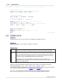
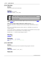
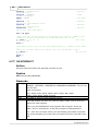
Remarks
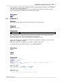
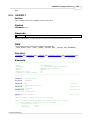
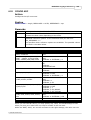
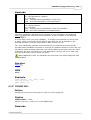
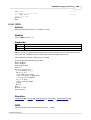
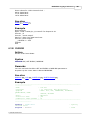
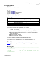
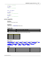
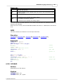
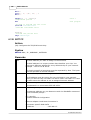
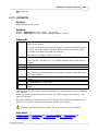
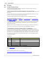
Togglebit
Address
Command
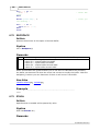
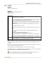
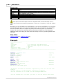
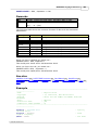
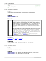
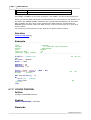
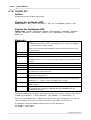
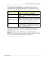
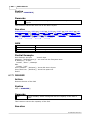
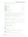
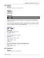
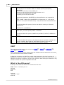
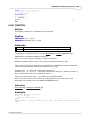
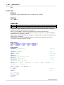
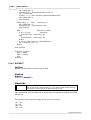
Make the toggle bit 0 or 32 to set the toggle bit
The RC5 address
The RC5 command.
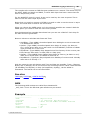
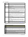
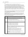
Normal RC5 code uses 2 leading bits with the value '1'. After that the toggle bit
follows.
With extended RC5, the second bit is used to select the bank. When you make it 1
(the default and normal RC5) the RC5 code is compatible. When you make it 0, you
select bank 0 and thus use extended RC5 code.
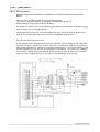
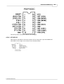
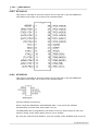
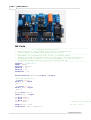
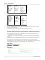
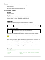
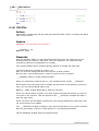
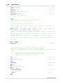
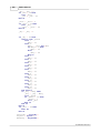
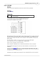
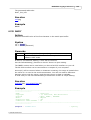
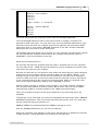
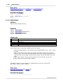
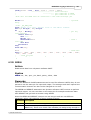
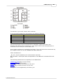
The resistor must be connected to the OC1A pin. In the example a 2313 micro was
used. This micro has pin portB.3 connected to OC1A.
Look in a data sheet for the proper pin when used with a different chip.
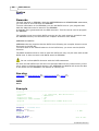
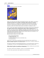
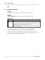
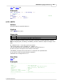
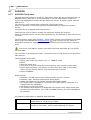
Most audio and video systems are equipped with an infra-red remote control.
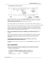
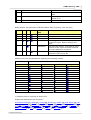
The RC5 code is a 14-bit word bi-phase coded signal.
The two first bits are start bits, always having the value 1.
The next bit is a control bit or toggle bit, which is inverted every time a button is
pressed on the remote control transmitter.
Five system bits hold the system address so that only the right system responds to
the code.
Usually, TV sets have the system address 0, VCRs the address 5 and so on. The
command sequence is six bits long, allowing up to 64 different commands per
address.
The bits are transmitted in bi-phase code (also known as Manchester code).
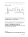
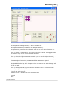
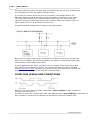
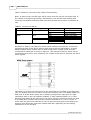
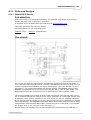
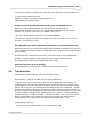
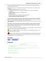
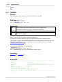
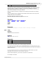
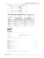
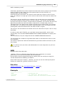
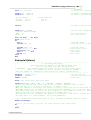
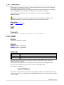
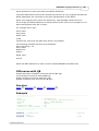
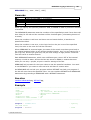
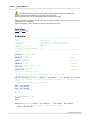
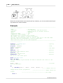
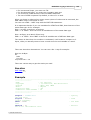
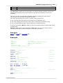
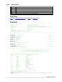
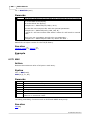
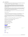
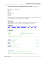
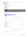
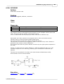
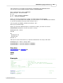
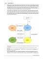
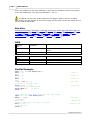
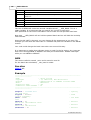
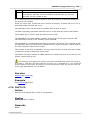
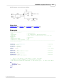
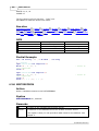
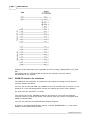
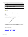
An IR booster circuit is shown below:
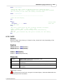
See also
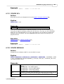
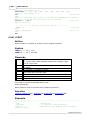
CONFIG RC5
442
, GETRC5
594
, RC6SEND
692
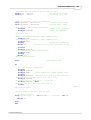
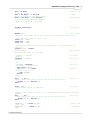
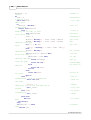
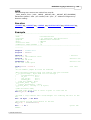
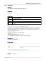
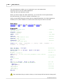
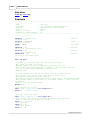
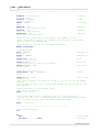
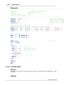
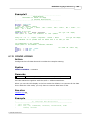
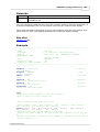
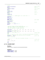
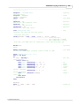
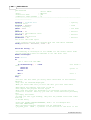
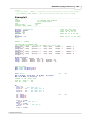
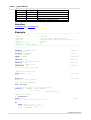
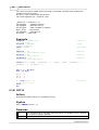
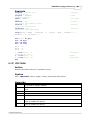
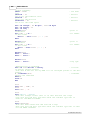
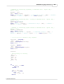
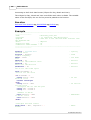
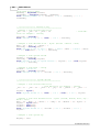
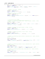
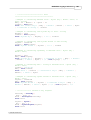
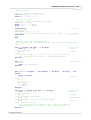
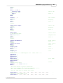
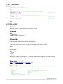
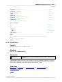
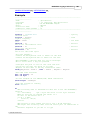
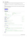
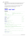
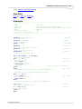
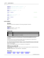
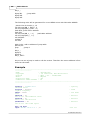
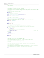
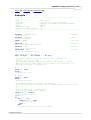
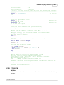
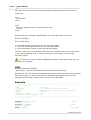
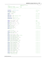
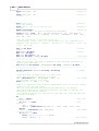
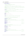
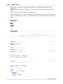
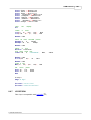
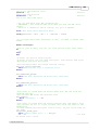
Example
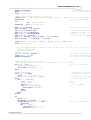
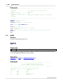
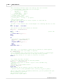
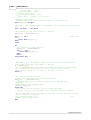
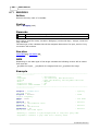
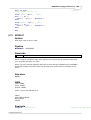
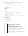
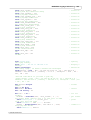
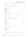
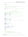
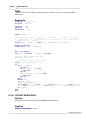
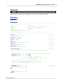
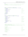
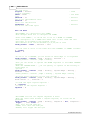
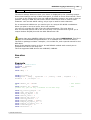
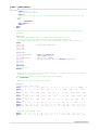
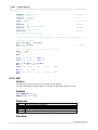
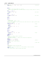
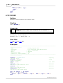
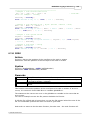
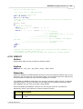
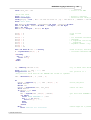
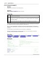
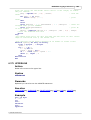
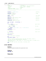
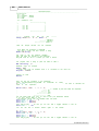
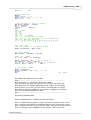
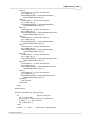
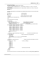
'---------------------------------------------------------------------------------------'name
: sendrc5.bas
'copyright
: (c) 1995-2005, MCS Electronics
'purpose
: code based on application note from Ger
Langezaal
© 2008 MCS Electronics