1
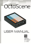
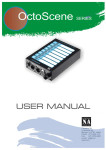
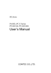
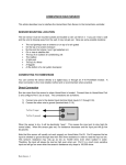
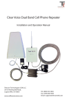
TABLE OF CONTENTS
1. BEFORE YOU BEGIN............................................................................................................. 3
WHAT IS INCLUDED
3
UNPACKING INSTRUCTIONS
3
AC POWER
3
Power-Up Procedure
3
CONTACT US
3
SAFETY INSTRUCTIONS
4
2. INTRODUCTION ..................................................................................................................... 5
FEATURES
5
DMX CHANNEL SUMMARY
5
PRODUCT OVERVIEW
6
3. SETUP..................................................................................................................................... 8
FUSE REPLACEMENT
8
FIXTURE LINKING
8
Data Cabling
9
DMX Data Cable
9
Cable Connectors
9
3-Pin to 5-Pin Conversion Chart
9
SETTING UP A DMX SERIAL DATA LINK
10
MOUNTING
10
Orientation
10
Rigging
10
4. OPERATING INSTRUCTIONS............................................................................................... 11
NAVIGATING THE CONTROL PANEL
11
MENU Function
11
MENU Map
12
Function descriptions
13
DMX CHANNEL VALUES
13
DMX Channel Values 3C mode
14
DMX Channel Values 4C mode
15
5. APPENDIX................................................................................................................................. 16
DMX PRIMER
16
GENERAL MAINTENANCE
16
RETURN PROCEDURE
17
CLAIMS
17
TECHNICAL SPECIFICATIONS
18
PowerFlash User manual version 1.0
06.2011
2
1. BEFORE YOU BEGIN
What is included in PowerFlash
► 1 x PowerFlash
► 1 x Lamp XOP 15
► Warranty Card
► Users Manual
What is included in ColorFlash
► 1 x ColorFlash
► Warranty Card
► Users Manual
Unpacking Instructions
Immediately upon receiving a fixture, carefully unpack the carton, check the contents to
ensure that all parts are present, and have been received in good condition. Notify the shipper
immediately and retain packing material for inspection if any parts appear damaged from shipping
or the carton it self shows signs of mishandling. Save the carton and all packing materials. In the
event that a fixture must be returned to the factory, it is important that the fixture be returned in the
original factory box and packing.
AC Power
The only thing necessary to do before powering on the unit is to make sure the line
voltage you are applying is within the range of accepted voltages. This fixture will accommodate
190V - 240V AC 45/65 Hz. All fixtures must be powered directly off a switched circuit and can not
run off a rheostat (variable resistor) or dimmer circuit, even if the rheostat or dimmer channel is
used solely for a 0% to 100% switch.
Power-Up Procedure
Switching on the power PowerFlash performs a pre-programmed self-test. If the test is
revealed a fault , that prevents the normal operation of the fixture, display shows at the end of the
test legend „Err”. In this case the fixture signals about the damage for some time blinking. Then
pressing any button on the control panel, the display indicates for all the errors:
„cXY” – where ”c” means it is the color changer error indication. „X” is tape or motor error
number. „Y” is position sensor error
After that, on the control panel display is shown planted DMX address and the PowerFlash enters
the work state
Contact Us
General Information Company NA
9 Lambertu street
Marupe, LV-2167, Latvia
Phone: +37167801110
Fax: +37167556505
e-mail: [email protected]
web: www.na.lv
PowerFlash User manual version 1.0
06.2011
3
Safety Instructions
Please read these instructions carefully, which includes important
information about the installation, usage and maintenance of this
product.
●
●
●
●
●
●
●
●
●
●
●
Please keep this User Guide for future consultation. If you sell the unit to another user, be sure
that they also receive this instruction booklet.
Always make sure that you are connecting to the proper voltage, and that the line voltage you
are connecting to is not higher than that stated on the decal or rear panel of the fixture.
Make sure there are no flammable materials close to the unit while operating.
Always disconnect from power source before servicing or replacing fuse and be sure to replace
with same fuse source.
Secure fixture to fastening device using a safety chain.
Maximum ambient temperature (Ta) is (40°C). Do not operate fixture at temperatures higher
than this.
In the event of a serious operating problem, stop using the unit immediately. Never try to repair
the unit by yourself. Repairs carried out by unskilled person can lead to damage or
malfunction. Please contact the nearest authorized technical assistance center. Always use the
same type spare parts.
Don’t connect the device to a dimmer pack.
Make sure the power cord is never crimped or damaged.
Never disconnect the power cord by pulling or tugging on the cord.
Avoid direct eye exposure to the light source while it is on.
Caution! There are no user serviceable parts inside the unit. Do not open the housing or attempt any repairs
yourself. In the unlikely event your unit may require service, please contact „Company NA” at:
+37167801110.
PowerFlash User manual version 1.0
06.2011
4
2. INTRODUCTION
Features
● 3 and 4 channel DMX-512 stroboscope fixture
● Various flash intensity 0% - 100%
● Flash Duration control 0ms – 650ms
● Flash Rate control 0flash – 33 flashes per second
● Continous blinder effect up to 30 seconds with 3000W
● Flash intensity curve selection
● LED control panel display
Additional Features
● Aviable optional color changer unit with 11 colors ( ColorFlash )
● Aviable optional beam clamp
● Aviable optional safety cable
● Aviable optional road case ( 4 PowerFlash and 4 ColorFlash )
PowerFlash - 3 kW stroboscope with powerful Blinder effect in 50Hz or 100Hz modes. Possible to
control flash intensity, frequency, duration flash curves and effects. Continues blinder effect with max
power. For smooth and intelligent flash - 100Hz mode, ideal for TV productions. Optional data/power
output for ColorFlash color changer, made for PowerFlash strobe. PowerFlash provides use in touring,
disco clubs, concerts, theatre performances or TV.
ColorFlash is color changer designed for use together with high output strobes. High speed color
frame changing function as well as effective cooling system allow to create colorful strobe, blinder and
fade effects. The ColorFlash do not require additional power supply unit in case of usage together with
Power-Flash strobe, or optional 2 or 8 changer power supply units available in case of other brand
strobes.
3C (3 channel mode)
CHANNEL
FUNCTION
1
Flash intensity
2
Flash duration
3
Flash rate
4
ColorFlash ( if connected )
4C (4 channel mode)
CHANNEL
FUNCTION
1
Flash intensity
2
Flash duration
3
Flash rate
4
Flash intensity curve selection
5
ColorFlash ( if connected )
PowerFlash User manual version 1.0
06.2011
5
PowerFlash Overview
PowerFlash User manual version 1.0
06.2011
6
ColorFlash Overview
PowerFlash User manual version 1.0
06.2011
7
3. SETUP
Disconnect the power cord before replacing a fuse
and always replace with the same type fuse.
Fuse Replacement
The fuse for this fixture is located outside the chassis. Remove the damaged fuse from its
holder and replace with exact same type fuse. Reconnect power.
Fixture Linking
You will need a DMX data link to run light shows of one or more fixtures using a DMX-512
lighting console. The combined number of channels required by all the fixtures on a DMX
data link determines the number of fixtures the DMX data link can support.
Important: Fixtures on a DMX data link must be daisy chained in one single line. To
comply with the EIA-485 standard no more than 32 devices should be
connected on one data link. Connecting more than 32 fixtures on one
serial data link without the use of a DMX optically-isolated splitter may
result in deterioration of the digital DMX signal.
Maximum recommended DMX data link distance between fixtures: 300 meters (984 ft.)
DMX DATA CABLE
Use a Belden© 9841 or equivalent cable which meets the specifications for EIA RS-485
applications. Standard microphone cables cannot transmit DMX data reliably over long
distances. The cable will have the following characteristics:
2-conductor twisted pair plus a shield
Maximum capacitance between conductors – 30 pF/ft.
Maximum capacitance between conductor and shield – 55 pF/ft.
Maximum resistance of 20 ohms / 1000 ft.
Nominal impedance 100 – 140 ohms
PowerFlash User manual version 1.0
06.2011
8
CABLE CONNECTORS
Cabling must have a male XLR connector on one end and a female XLR connector on the
other end.
DMX connector configuration
CAUTION
Do not allow contact between the common and the fixture’s chassis
ground. Grounding the common can cause a ground loop, and your
fixture may perform erratically. Test cables with an ohm meter to verify
correct polarity and to make sure the pins are not grounded or shorted
to the shield or each other.
3-PIN TO 5-PIN CONVERSION CHART
NOTE !
If you use a console with a 5 pin DMX output connector, you will need
to use a 5 pin to 3 pin adapter. The chart below details a proper cable
conversion:
3-PIN TO 5-PIN CONVERSION CHART
Conductor
3 Pin Female (output)
5 Pin Male (Input)
Ground / Shield
Data ( - ) signal
Pin 1
Pin 1
Pin 2
Pin 2
Data ( + ) signal
Pin 3
Pin 3
Do not use
Do not use
Do not use
Do not use
PowerFlash User manual version 1.0
06.2011
9
Setting up a DMX Serial Data Link
1. Connect the (male) 5 pin XLR connector side of the DMX cable to the output (female) 5
pin XLR connector of the DMX console. Connect the end of the cable coming from the DMX console
which will have a (female) 5 pin XLR connector to the input connector of the fixture consisting of a
(male) 5 pin XLR connector.
2. Then, proceed to connect from the fixture output as stated above to the input of the
following fixture and so on.
3. Then, coninue the linking till last planted fixture is conected in your DMX signal data chain.
Mounting
ORIENTATION
This fixture may be mounted in any position provided there is adequate room for ventilation.
RIGGING
Hanging Clamps
It is important never to obstruct the fan or vents pathway. Mount the
fixture using, a suitable “C” or “O” type clamp. Adjust the angle of the
fixture by loosening both knobs and tilting the fixture. After finding the
desired position, retighten both knobs.
● When selecting installation location, take into consideration lamp
replacement access and routine maintenance.
● Safety cables must always be used.
● Never mount in places where the fixture will be exposed to rain, high
humidity, extreme temperature changes or restricted ventilation.
NOTE !
Clamp is sold separately.
PowerFlash User manual version 1.0
06.2011
10
4. OPERATING INSTRUCTIONS
Navigating the Control Panel
Access control panel functions using the three control panel buttons located directly underneath the LCD
Display.
Button
Function
<MENU>
Used to access the menu. And used to
select and store the current menu or option
within a menu.
<UP>
Scrolls through menu options in ascending
order.
<DOWN>
Scrolls through menu options in descending
order
The Control Panel LED Display shows the menu items you select from the menu map on page #.
When a menu function is selected, the display will show immediately the first available option for the
selected menu function. To select a menu item, press <MENU>.
Press and hold the <MENU> button to scroll through the top level menu items. This is the top of the menu
map. Use the <UP> and <DOWN> buttons to navigate the menu map and menu options. Press the <MENU>
button to access the menu function currently displayed or to enable a menu option. To return to the top of the
menu map or menu without changing the value, press the <MENU> button.
Menu Functions:
Adr
tSt
Con
tEr
U in
Frq
PoL
dIS
dEF
–––
–
–
–
–
–
–
–
–
–
–
DMX address selection
Pre-programmed self test
Channel configuration
Internal thermometer
Mains power
Frequence
Power limit
Display
Factory defaults
Exit from menu
Normally operation of the system during the Control Panel LED Display indicates DMX start address. When
the DMX signal is not connected, or for any other reason, PowerFlash does not receive DMX signal, the
Display blinks.
PowerFlash User manual version 1.0
06.2011
11
Menu Map
Adr
001 - 512
tSt
1
Con
3C
4C
2
3
4
tEr
30.2
5
U in
233.
Frq
PoL
6
50
7
100
8
0.50
0.75
1.00
dIS
on
OFF
dEF
YES
no
---
PowerFlash User manual version 1.0
06.2011
12
Function Description
Adr – Use the <UP> and <DOWN> buttons to enter the DMX address from 1 to 512. Holding the <UP> and
<DOWN> buttons change in address happen to acceleration. Blinking indicator means the
unconfirmed address. To confirm the address press <MENU> button. Only after the <MENU> button
is pressed address is changed. After the defeat on the display will be shown to the last confirmed
DMX address.
tSt – Will be activated the pre-programmed self test. It is possible the eight test versions:
1
2
3
4
5
6
7
8
- Flash intensity 100%, Flash Rate 3Hz
- Flash intensity 100%, Flash Rate 4Hz
- Flash intensity 100%, Flash Rate 11Hz
- Flash intensity 100%, Flash Rate 14Hz
- Flash intensity 100%, Flash Rate 18Hz
- Flash intensity 100%, Flash Rate 21Hz
- Flash intensity 100%, Flash Rate 25Hz
- Flash intensity 0%, Flash Reate 0Hz
During the test, using the <UP> and <DOWN> buttons you can change the test versions. To exit tSt
mode, you need to press and hold the <MENU> button.
Con – DMX control mode selection. The PowerFlash has 2 operating modes. In each of the control modes
fixture occupies different DMX adresses quantity and are various controlled:
DMX modes
3C
4C
Address number
3
4
Mode description
3 chanel mode - Flash intensity, duration, reate control
4 chanel mode - Flash intensity, duration, reate, curve type
If at the PowerFlash XLR-4 pin output is attached to a color changer unit
(ColorFlash), then at any PowerFlash control mode are added one more
DMX channel that provides the color changer control ! See DMX channel
values ...
tEr – Built-in thermometer will provide full information about fixtures the current temperature.
U in – Mains voltage
Frq – Chenge frequency 50Hz to 100Hz***
Warning!!! *** 100 Hz frequency setting requires to use a 20A circuit breakers if you work in
220V AC, and wire cross section must be at least 2.5 square.
As well as this mode shortens the lamp life (and color gel for ColorFlash or added
scroler).
PoL – Power limit - limiting the average and peak power. Chose 1.00 - device works in full
(100%) power range. Power of device can be limited to 0.75 (75%) and 0.50 (50%).
dIS – Display on/OFF. Dispaly is switched on all the time or switches off in standby mode.
dEF – Set factory default.
--- – Exit from the menu and return to working mode.
PowerFlash User manual version 1.0
06.2011
13
DMX Channel Values
DMX Channel Values 3C mode (50Hz)
Channel
Value
1
000 ↔ 003
003 ↔ 255
2
000 ↔ 255
3
000 ↔ 003
003 ↔ 255
4
000 ↔ 255
Function
Flash intensity
lamp is turned off
lamp dimming up to 100%
Flash duration
0ms – 650ms 100%
Flash reate
No flash
0.5Hz – 25Hz
ColorFlash control if connected
11 colours
0 – 100%
DMX Channel Values 3C mode (100Hz)***
Channel
Value
1
000 ↔ 003
003 ↔ 255
2
000 ↔ 255
3
000 ↔ 003
003 ↔ 255
4
000 ↔ 255
Function
Flash intensity
lamp is turned off
lamp dimming up to 100%
Flash duration
0ms – 650ms 100%
Flash reate
No flash
0.5Hz – 100Hz***
ColorFlash control if connected
11 colours
0 – 100%
***
Warning!
100 Hz frequency setting requires to use a 20A circuit breakers if you work in 220V AC, and wire cross
section must be at least 2.5 square.
As well as this mode shortens life of the lamp (and color gel for ColorFlash or added scroler).
PowerFlash User manual version 1.0
06.2011
14
DMX Channel Values 4C mode (50Hz)
Channel
Value
1
000 ↔ 003
003 ↔ 255
2
000 ↔ 255
3
000 ↔ 003
003 ↔ 255
4
000 ↔ 005
006 ↔ 042
043 ↔ 085
086 ↔ 128
129 ↔ 171
172 ↔ 214
215 ↔ 255
5
000 ↔ 255
Function
Flash intensity
lamp is turned off
lamp dimming up to 100%
Flash duration
0ms – 650ms 100%
Flash reate
No flash
0Hz – 25Hz
Flash intensity curve selection
No special intensity curves
Ramp up
Ramp-down
Ramp-up-down
Random
Lighting
Spikes
ColorFlash control if connected
11 colours
0 – 100%
DMX Channel Values 4C mode (100Hz)***
Channel
Value
1
000 ↔ 003
003 ↔ 255
2
000 ↔ 255
3
000 ↔ 003
003 ↔ 255
4
000 ↔ 005
006 ↔ 042
043 ↔ 085
086 ↔ 128
129 ↔ 171
172 ↔ 214
215 ↔ 255
5
000 ↔ 255
Function
Flash intensity
lamp is turned off
lamp dimming up to 100%
Flash duration
0ms – 650ms 100%
Flash reate
No flash
0.5Hz – 100Hz***
Flash intensity curve selection
No special intensity curves
Ramp up
Ramp-down
Ramp-up-down
Random
Lighting
Spikes
ColorFlash control if connected
11 colours
0 – 100%
***
Warning!
100 Hz frequency setting requires to use a 20A circuit breakers if you work in 220V AC, and wire cross
section must be at least 2.5 square.
As well as this mode shortens the lamp life (and color gel for ColorFlash or added scroler).
PowerFlash User manual version 1.0
06.2011
15
5. APPENDIX
DMX Primer
There are 512 channels in a DMX-512 connection. Channels may be assigned in any manner.
A fixture capable of receiving DMX 512 will require one or a number of sequential channels.
The user must assign a starting address on the fixture that indicates the first channel reserved
in the lighting console. There are many different types of DMX controllable fixtures and they all
may vary in the total number of channels required. Choosing a start address should be
planned in advance. Channels should never overlap. If they do, this will result in erratic
operation of the fixtures whose starting address is set incorrectly. You can however, control
multiple fixtures of the same type using the same starting address as long as the intended
result is that of unison movement or operation. In other words, the fixtures will be slaved
together and all respond exactly the same.
DMX fixtures are designed to receive data through a DMX Chain. A DMX Chain connection is
where the DMX OUT of one fixture connects to the DMX IN of the next fixture. The order in
which the fixtures are connected is not important and has no effect on how a lihgting console
communicates to each fixture. Use an order that provides for the easiest and most direct
cabling. Connect fixtures using shielded two conductor twisted pair cable with three pin XLR
male to female connectors. The shield connection is pin 1, while pin 2 is Data Negative (S-)
and pin 3 is Data positive (S+). Company NA carries 3-pin and 5-pin XLR DMX compliant
cables.
General Maintenance
To maintain optimum performance and minimize wear fixtures should be cleaned frequently.
Usage and environment are contributing factors in determining frequency. As a general rule,
fixtures should be cleaned at least twice a month. Dust build up reduces light output
performance and can cause overheating. This can lead to reduced lamp life and increased
mechanical wear. Be sure to power off fixture before conducting maintenance.
Unplug fixture from power. Use a vacuum or air compressor and a soft brush to remove dust
collected on external vents and internal components. Clean all glass when the fixture is cold
with a mild solution of glass cleaner or Isopropyl Alcohol and a soft lint free cotton cloth or lens
tissue. Apply solution to the cloth or tissue and drag dirt and grime to the outside of the lens.
Gently polish optical surfaces until they are free of haze and lint.
The cleaning of internal and external optical lenses and/or mirrors must be carried out
periodically to optimize light output. Cleaning frequency depends on the environment in which
the fixture operates: damp, smoky or particularly dirty surrounding can cause greater
accumulation of dirt on the unit’s optics. Clean with soft cloth using normal glass cleaning fluid.
- Always dry the parts carefully. – Clean the external optics at least every 20 days. Clean the
internal optics at least every 30 / 60 days.
PowerFlash User manual version 1.0
06.2011
16
Return Procedure
Returned merchandise must be sent prepaid and in the original packing, call tags will not be
issued. Package must be clearly labeled with a Return Merchandise Authorization Number
(RMA #). Products returned without an RMA # will be refused. Call Company NA and request
RMA # prior to shipping the fixture. Be prepared to provide the model number, serial number
and a brief description of the cause for the return. Be sure to properly pack fixture, any
shipping damage resulting from inadequate packaging is the customer’s responsibility.
Company NA reserves the right to use its own discretion to repair or replace product(s). As a
suggestion, proper UPS packing or double-boxing is always a safe method to use.
Note: If you are given an RMA #, please include the following information on a piece
of paper inside the box:
1) Your name
2) Your address
3) Your phone number
4) The RMA #
5) A brief description of the symptoms
Claims
Damage incurred in shipping is the responsibility of the shipper; therefore the damage must be
reported to the carrier upon receipt of merchandise. It is the customer's responsibility to notify
and submit claims with the shipper in the event that a fixture is damaged due to shipping. Any
other claim for items such as missing component/part, damage not related to shipping, and
concealed damage, must be made within seven (7) days of receiving merchandise.
PowerFlash User manual version 1.0
06.2011
17
PowerFlash Technical Specifications
WEIGHT & DIMENSIONS
Length ............................................................................................................ 433 mm
Width ..............................................................................................................130 mm
Height ..............................................................................................................240 mm
Weight .................................................................................................................4,9 kg
POWER
Operating Voltage ....................................................................190V ~ 240V 45/65 Hz
Fuse.......................................................................................................................20A
Power Consumption (50Hz mode)...................................................................... 3000W
Power Consumption (100Hz mode).................................................................... 4500W
LIGHT SOURCE
Lamp............................................................................................................... XOP 15
THERMAL
Maximum ambient temperature............................................................................+40°C
Minimum ambient temperature........................ .....................................................-25°C
Cooling ............................................... .................................................. air cooled - fan
CONTROL & PROGRAMMING
DMX input ..................................................................... locking 5-pin XLR male socket
DMX output ................................................................ locking 5-pin XLR female socket
Data + power output for ColorFlash .......................... locking 4-pin XLR female socket
DMX pin config. ...........pin 1 shield, pin 2 (-), pin 3 (+), pin 4 don’t use, pin 5 don’t use
Protocol........................................................................................................... DMX-512
DMX Channels ..................................................................................................3 , 4 , 5
WARRANTY INFORMATION
Warranty................................................................................... 2-year limited warranty
PowerFlash User manual version 1.0
06.2011
18
ColorFlash Technical Specifications
WEIGHT & DIMENSIONS
Length ............................................................................................................ 500 mm
Width .............................................................................................................. 30 mm
Height ..............................................................................................................300 mm
Weight .................................................................................................................3,4 kg
POWER
Operating Voltage ...........................................................................................24 V DC
Power Consumption....................................................................................max. 0.15A
Aviable optional power supply for 2 or 8 Color Flash units
Colours
Color changer..................................................................................................11 colors
THERMAL
Maximum ambient temperature............................................................................+40°C
Minimum ambient temperature........................ .....................................................-25°C
Cooling ............................................... .................................................. air cooled - fan
CONTROL & PROGRAMMING
Data + power input ...................................................... locking 4-pin XLR male socket
Protocol........................................................................................................... DMX-512
DMX Channels ............................................................................................................ 1
WARRANTY INFORMATION
Warranty................................................................................... 2-year limited warranty
Gel
position
0
1
2
3
4
5
6
7
8
9
10
Color
Clear
Straw
Pale Amber Gold
Orange
Red
Broadway Pink
Light Lavender
Aquamarine
Green Blue
Light Green
Blue Glass
Dimension
350x372mm
300x372mm
300x372mm
300x372mm
300x372mm
300x372mm
300x372mm
300x372mm
300x372mm
300x372mm
350x372mm
PowerFlash User manual version 1.0
No.
R-00
R-12
R-09
R-23
R-26
R-339
R-52
R-363
R-77
R-88
R-2005
06.2011
Manufacturer
Rosco
Rosco
Rosco
Rosco
Rosco
Rosco
Rosco
Rosco
Rosco
Rosco
Rosco
Level
0<100%
0%
10 %
20 %
30 %
41 %
50 %
61 %
71 %
81 %
90 %
100%
Level
0<255
0
25
48
71
94
130
156
181
207
230
255
19