1
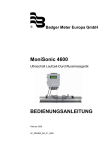
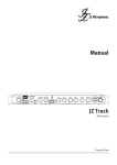
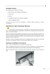
TABLE OF CONTENTS
1. BEFORE YOU BEGIN............................................................................................................. 3
WHAT IS INCLUDED
3
UNPACKING INSTRUCTIONS
3
AC POWER
3
CONTACT US
3
SAFETY INSTRUCTIONS
4
2. INTRODUCTION ..................................................................................................................... 5
FEATURES
5
Description
5
PRODUCT OVERVIEW
5
3. SETUP..................................................................................................................................... 6
FUSE REPLACEMENT
6
FIXTURE LINKING
6
Data Cabling
6
DMX Data Cable
6
Cable Connectors
7
3-Pin to 5-Pin Conversion Chart
7
SETTING UP A DMX SERIAL DATA LINK
7
MOUNTING
8
Orientation
8
4. OPERATING INSTRUCTIONS............................................................................................... 8
Operating
8
Signal processing
8
DMX Splitter output connection to input
8
LED indicator positions
9
5. APPENDIX............................................................................................................................... 10
DMX PRIMER
10
GENERAL MAINTENANCE
10
RETURNS PROCEDURE
11
CLAIMS
11
TECHNICAL SPECIFICATIONS
12
DMX Splitter IP65 User Manual version 1.0
06.2011
2
1. BEFORE YOU BEGIN
What is included
► 1 x DMX Splitter IP65 unit
► 1 x Warranty Card
► 1 x Users Manual
Unpacking Instructions
Immediately upon receiving a unit, carefully unpack the carton, check the contents to
ensure that all parts are present, and have been received in good condition. Notify the shipper
immediately and retain packing material for inspection if any parts appear damaged from shipping
or the carton it self shows signs of mishandling. Save the carton and all packing materials. In the
event that a unit must be returned to the factory, it is important that the unit be returned in the
original factory box and packing.
AC Power
The only thing necessary to do before powering on the unit is to make sure the line
voltage you are applying is within the range of accepted voltages. This unit will accommodate 85265V AC, 47 / 63 Hz. All units must be powered directly off a switched circuit and cannot be run off
a rheostat (variable resistor) or dimmer circuit, even if the rheostat or dimmer channel is used
solely for a 0% to 100% switch.
Contact Us
General Information Company NA
9 Lambertu street
Marupe, LV-2167, Latvia
Phone: +371 6780 1111
Fax: +371 6755 6505
e-mail: [email protected]
web: www.na.lv
DMX Splitter IP65 User Manual version 1.0
06.2011
3
Safety Instructions
Please read these instructions carefully, which includes important
information about the installation, usage and maintenance of this
product.
●
●
●
●
●
●
●
●
●
●
●
Please keep this User manual for future consultation. If you sell the unit to another user, be
sure that they also receive this instruction booklet.
Always make sure that you are connecting to the proper voltage, and that the line voltage you
are connecting to is not higher than that stated on the decal or rear panel of the unit.
Make sure there are no flammable materials close to the unit while operating.
Always disconnect from power source before servicing or replacing fuse and be sure to replace
with same fuse source.
Secure unit to fastening device using a safety chain.
Maximum ambient temperature (Ta) is (40°C). Do not operate unit at temperatures higher than
this.
In the event of a serious operating problem, stop using the unit immediately. Never try to repair
the unit by yourself. Repairs carried out by unskilled people can lead to damage or
malfunction. Please contact the nearest authorized technical assistance center. Always use the
same type spare parts.
Don’t connect the device to a dimmer pack.
Make sure the power cord is never crimped or damaged.
Never disconnect the power cord by pulling or tugging on the cord.
Avoid direct eye exposure to the light source while it is on.
Caution! There are no user serviceable parts inside the unit. Do not open the housing or attempt any repairs
yourself. In the unlikely event your unit may require service, please contact
„Company NA” at: +371 6780 1111.
DMX Splitter IP65 User Manual version 1.0
06.2011
4
2. INTRODUCTION
Features
● DMX-512 IP65 signal splitter
● DMX inputs: 1
● DMX outputs: 1+4
● IP65 protected housing
● There are 2 LED status indicators
Additional Features
● Available in silver
● Optional IP65 protected DMX connectors: Neutrik NC5 F/M-HD
Description
The Company NA manufactured DMX IP65 signal splitter is designed for outdoor use from very cold
to very hot conditions and it is IP65 rated. DMX signal splitter is used for standard DMX-512A signal
amplification and splitting to multiple outputs. The splitter has 1 optically isolated DMX input, 1 through output
and 4 optically isolated outputs. Available with hard wired data connectors.
Product Overview
DMX Splitter IP65 User Manual version 1.0
06.2011
5
3. SETUP
Disconnect the power cord before replacing a fuse
and always replace with the same type fuse.
Fixture Linking
You will need a DMX data link to run light shows of one or more fixtures using a DMX-512
lighting console. The combined number of channels required by all the fixtures on a DMX
data link determines the number of fixtures the DMX data link can support.
Important: Fixtures on a DMX data link must be daisy chained in one single line. To
comply with the EIA-485 standard no more than 32 devices should be
connected on one data link. Connecting more than 32 fixtures on one
serial data link without the use of a DMX optically-isolated splitter may
result in deterioration of the digital DMX signal.
Maximum recommended DMX data link distance between fixtures: 300 meters (984 ft.)
DMX DATA CABLE
Use a Belden© 9841 or equivalent cable which meets the specifications for EIA RS-485
applications. Standard microphone cables cannot transmit DMX data reliably over long
distances. The cable will have the following characteristics:
2-conductor twisted pair plus a shield
Maximum capacitance between conductors – 30 pF/ft.
Maximum capacitance between conductor and shield – 55 pF/ft.
Maximum resistance of 20 ohms / 1000 ft.
Nominal impedance 100 – 140 ohms
DMX Splitter IP65 User Manual version 1.0
06.2011
6
CABLE CONNECTORS
Cabling must have a male XLR connector on one end and a female XLR connector on the
other end.
DMX connector configuration
CAUTION
Do not allow contact between the common and the fixture’s chassis
ground. Grounding the common can cause a ground loop, and your
fixture may perform erratically. Test cables with an ohm meter to verify
correct polarity and to make sure the pins are not grounded or shorted
to the shield or each other.
3-PIN TO 5-PIN CONVERSION CHART
NOTE !
If you use a console with a 5 pin DMX output connector, you will need
to use a 5 pin to 3 pin adapter. The chart below details a proper cable
conversion:
3-PIN TO 5-PIN CONVERSION CHART
Conductor
3 Pin Female (output)
5 Pin Male (Input)
Ground / Shield
Pin 1
Pin 1
Data ( - ) signal
Pin 2
Pin 2
Data ( + ) signal
Pin 3
Pin 3
Do not use
Do not use
Do not use
Do not use
Setting up a DMX Serial Data Link
1. Connect the (male) connector side of
the DMX cable to the output (female)
connector of the lighting concole.
2. Connect the end of the cable coming from
the lighting console which will have a (female) 3
connector to the input connector of the
DMX Splitter consisting of a (male)
connector.
3. Then, proceed to connect from the output
as stated above to the input of the following
fixture and so on.
DMX Splitter IP65 User Manual version 1.0
06.2011
7
Mounting
ORIENTATION
This unit may be mounted in any position.
4. OPERATING INSTRUCTIONS
Operating
DMX Splitter IP65 has two types of DMX outputs: one output without optical isolation; four outputs with
optical isolation up to 1000V.
Signal processing:
DMX signal splitter is used for standard DMX-512A signal amplification and splitting to multiple
outputs. The splitter has 1 optically isolated DMX input, 1 through output and 4 optically isolated outputs.
Available with hard wired data connectors or tail Neutrik NC5 M/F X-HD series data connectors.
This unit provide the DMX signal reinforcement at the outputs 2-5. Upon receipt of DMX signal,it is
recorded in device memory, and then straightened the signal distortion components. Then at the DMX
Splitter IP65 output is fed DMX signal with the proper DMX curve. At this outputs signal processing signal
delay is 0.1 μsek.
At the first DMX output signal processing is not performed.
DMX Splitter IP65 User Manual version 1.0
06.2011
8
LED indicator positions
„POWER” - Power LED indicator ( green ) has two positions:
● Off - Power is not connected;
● On - Power is connected.
„DATA” - DMX input signal LED indicator is located at the top of the unit and indicate whether the DMX
signal recieve at the input. DMX input signal LED indicator (yellow) has two positions:
● Off - DMX signal is not received;
● Blink - DMX signal is recieved.
DMX Splitter IP65 User Manual version 1.0
06.2011
9
5. APPENDIX
DMX Primer
There are 512 channels in a DMX-512 connection. Channels may be assigned in any manner.
A fixture capable of receiving DMX 512 will require one or a number of sequential channels.
The user must assign a starting address on the fixture that indicates the first channel reserved
in the lighting console. There are many different types of DMX controllable fixtures and they all
may vary in the total number of channels required. Choosing a start address should be
planned in advance. Channels should never overlap. If they do, this will result in erratic
operation of the fixtures whose starting address is set incorrectly. You can however, control
multiple fixtures of the same type using the same starting address as long as the intended
result is that of unison movement or operation. In other words, the fixtures will be slaved
together and all respond exactly the same.
DMX fixtures are designed to receive data through a DMX Chain. A DMX Chain connection is
where the DMX OUT of one fixture connects to the DMX IN of the next fixture. The order in
which the fixtures are connected is not important and has no effect on how a lihgting console
communicates to each fixture. Use an order that provides for the easiest and most direct
cabling. Connect fixtures using shielded two conductor twisted pair cable with three pin XLR
male to female connectors. The shield connection is pin 1, while pin 2 is Data Negative (S-)
and pin 3 is Data positive (S+). Company NA carries 3-pin and 5-pin XLR DMX compliant
cables.
General Maintenance
To maintain optimum performance and minimize wear fixtures should be cleaned frequently.
Usage and environment are contributing factors in determining frequency. As a general rule,
fixtures should be cleaned at least twice a month. Dust build up reduces light output
performance and can cause overheating. This can lead to reduced lamp life and increased
mechanical wear. Be sure to power off fixture before conducting maintenance.
Unplug fixture from power. Use a vacuum or air compressor and a soft brush to remove dust
collected on external vents and internal components. Clean all glass when the fixture is cold
with a mild solution of glass cleaner or Isopropyl Alcohol and a soft lint free cotton cloth or lens
tissue. Apply solution to the cloth or tissue and drag dirt and grime to the outside of the lens.
Gently polish optical surfaces until they are free of haze and lint.
The cleaning of internal and external optical lenses and/or mirrors must be carried out
periodically to optimize light output. Cleaning frequency depends on the environment in which
the fixture operates: damp, smoky or particularly dirty surrounding can cause greater
accumulation of dirt on the unit’s optics. Clean with soft cloth using normal glass cleaning fluid.
- Always dry the parts carefully. – Clean the external optics at least every 20 days. Clean the
internal optics at least every 30 / 60 days.
DMX Splitter IP65 User Manual version 1.0
06.2011
10
Returns Procedure
Returned merchandise must be sent prepaid and in the original packing, call tags will not be
issued. Package must be clearly labeled with a Return Merchandise Authorization Number
(RMA #). Products returned without an RMA # will be refused. Call Company NA and request
RMA # prior to shipping the fixture. Be prepared to provide the model number, serial number
and a brief description of the cause for the return. Be sure to properly pack fixture, any
shipping damage resulting from inadequate packaging is the customer’s responsibility.
Company NA reserves the right to use its own discretion to repair or replace product(s). As a
suggestion, proper UPS packing or double-boxing is always a safe method to use.
Note: If you are given an RMA #, please include the following information on a piece
of paper inside the box:
1) Your name
2) Your address
3) Your phone number
4) The RMA #
5) A brief description of the symptoms
Claims
Damage incurred in shipping is the responsibility of the shipper; therefore the damage must be
reported to the carrier upon receipt of merchandise. It is the customer's responsibility to notify
and submit claims with the shipper in the event that a fixture is damaged due to shipping. Any
other claim for items such as missing component/part, damage not related to shipping, and
concealed damage, must be made within seven (7) days of receiving merchandise.
DMX Splitter IP65 User Manual version 1.0
06.2011
11
DMX Splitter IP65 Technical Specifications
WEIGHT & DIMENSIONS
Length .............................................................................................................295,0 mm
Width .............................................................................................................215.0 mm
Height ...............................................................................................................95,0 mm
Weight ................................................................................................................ 2,3 kg
POWER
Operating Voltage .......................................................................85-265V AC, 47/63 Hz
Power Consumption ........................................................................................7.5W max.
Input / Output isolation.................................................................... Optical up to 1000 V
THERMAL
Maximum ambient temperature............................................................................+50°C
Minimum ambient temperature........................ .....................................................-40°C
Cooling ............................................... ..................................................... convectional
IP protection ............................................................................................................. 65
CONTROL & PROGRAMMING
DMX input ............................................. 1 unit , tail Neutrik NC5 MX-HD male socket
DMX output ............................................1+4 units , Neutrik NC5 FX-HD female socket
DMX pin config. ...........pin 1 shield, pin 2 (-), pin 3 (+), pin 4 don’t use, pin 5 don’t use
Control ............................................................................................................ DMX-512
Signal delay in processing mode ......................................................................0,1 μsec.
WARRANTY INFORMATION
Warranty................................................................................... 2-year limited warranty
DMX Splitter IP65 User Manual version 1.0
06.2011
12