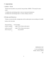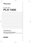
1
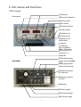
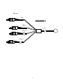
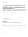
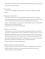
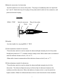
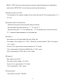
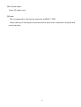
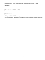
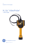
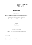
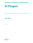
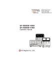
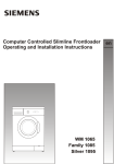
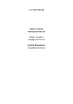
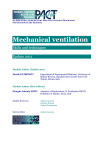
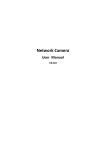
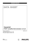
�����������������������������������������������
Laser Tissue Blood Oxygenation Monitor
BA4D9004-2
OMEGAMONITOR BOM-L1TR SF
OMEGAMONITOR
BOM-L1 TR SF
USER'S MANUAL
�
�CONTENTS
��������������
��������������������
Page
!
1.�Summary
!
2.�Part names and Function
!
3.�Connection to Recorder and Operation
!
4.�Theory
!
5.�Handling and Cautions
!
6.�Specifications
!
7.�Guarantee
!
!
!
!
!
!
!
!
!
!
!
!
!
!
!
!
!
!
!
2
3
10
13
17
20
21
�1
1. Summary
�This laser tissue blood oxygenation monitor, OMEGAMONITOR BOM-L1 TRSF, is an useful
instrument for measuring haemodynamics in a small portion of tissue, especially of brain,
muscle and skin of a small animal.
BOM-L1 TRSF can measure tissue blood volume and its oxygenation continuously and
noninvasively, and it is widely used from in fundermental research to in clinical
applications.
�BOM-L1 TRSF uses 3 laser diodes and their width of wavelength is narrow, then it causes
high S/N measurement. Also, our stabilizer system for the laser dioedes makes stable
measurement possible, and fast change of haemodynamics can be observed. The probe is
made from optical fibers, and it is not affected by electromagnetic noise.
The maximum measuring depth is almost the same length as the distance between the
probe and detector although it is dependent on a kind of tissue.�
�2
2.�Part names and Functions
1)Part names
①Indicator
②Detector indicator
Front panel
③Mode switch
④Set switch
⑤Distance switch
⑥Laser switch
⑦Indicator for
detector level
⑧Indicator for
probe level
⑨Optical
connectors
Red : Incidence
Black : Receiving
⑩Connector for
detector1, 2
⑪Handle
⑫Gain adjustment
switch nfor probe替ス
イッチ
⑬Gain adjustment
�プローブ用
switch for detector
本体背面部
⑭Selection switch
for indicator
⑮Selection switch
for AVG
⑯Outputs
⑰Power switch
⑱Ground terminal
⑲AC power input
����
�3
!
!
!
!
!
!
⑲Probe
Red
SF35 and SF-DS
Black
1
Gray 1
�
2
Gray 2
!
!
�4
2) Functions
!
① Indicator
�This indicator shows the measurement value of tissue blood oxygenation ratio and
total Hb volume.
�The tissue blood oxygenation ratio, StO2, is showed as persantage, and total Hb
volume, TOTAL Hb, is showed as 0〜100.0.
The oxy-Hb volume, OXY HB, and deoxy-Hb volume, DEDOXY Hb, are not showed in this
indicator, but all of StO2, Total Hb, OXY Hb and DEOXY Hb are obtained from the output
on the rear panel.
�Output mode has three modes. "MEA" mode is for measurement, "0" mode shows 0
(zero) on this indicator and sets the output to 0 (V), and "CAL" mode shows calibration
value and outputs its voltage. The calibration value of
StO2 on the indicator is 10.0 and the value of TOTAl Hb is 20.0. The calibration voltage
of the output of OXY Hb, DEOXY HB and StO2 are1.0 (V) respectively, and the voltaage
of TOTAL HB is 2.0(V).
TOTAL Hb = OXY Hb + DEOXY Hb�
!
② Mode switch
The output mode of "MEA"、"0" and "CAL" is selected by this switch.
!
③ Set switch
�This switch is used for measuring the value of change from a point. When this switch is
pushed, OXY-Hb, DEOXY-HB and TOTAL-Hb become zero. Then just the volume change
is obtained. However, StO2 is not affected by this switch. The red light shows "ON".
This switch is controlled when Mode switch shows "MEA", Laser switch is "ON",
Detector level shows green light and Probe level shows green light.
!
④ Distance switch
�5
�This switch is for normalizing the distance between Probe and Detector on tissue. Input
the distance as the unit of "mm".
!
⑤ Laser switch
Laser power is operated by this switch. Press this switch for ON and the red light
glows.
!
⑥ Indicator for detector level
�
This indicator shows the level of detected light intensity detected by the detector.
The haemodynamic values are obtained when this indicator shows green. When it shows
red at L or H level, adjust the detection level using "⑫Gain adjusting switch for
detector" to become green. L level means low detected light intensity, and H level does
high intensity for processing the signal.
The larger number of switch means higher gain.
!
⑦ Indicator for monitor level
�This indicator shoes the level of detected light intensity detected by the optical fiber
for monitor . This light intensity is used to compensate the output laser power on tissue
and absorption by pigment in the tissue. The haemodynamic values are obtained when
this indicator shows green. When it shows red at L or H level, adjust the detection level
using "⑪Gain adjusting switch for probe" to become green. L level means low detected
light intensity, and H level does high intensity for processing the signal.
The larger number of switch means higher gain.
!
⑧ Optical connectors for incidence and monitor
�Optical connectors to cennect the probe. The plugs of standard probes are�specified
by RED and BLACK. Match the key of the plug of the probe with the dich of the
connector, and push and screw the plug.
!
�6
⑨Optical connectors for detection
�Optical connectors to cennect the probe. The plugs of standard probes are�specified
by 1 and 2. Match the key of the plug of the probe with the dich of the connector, and
push and screw the plug.
!
����������Top View
�
�����BOM-L1 TRSF
Optical connector�����Plug of the probe
Ditch
Key
�
!
⑩ Handle
�Use this handle for carrying BOM-L1 TR SF.
!
⑪ Gain adjustment switch for monitor
�This selection switch is used to adjust the detected light intensity level of the probe.
Usually the position of "2" is widely used for many tissue. When dark tissue is measured
and the indicator shows red at L, set to "3".
When white tissue is measured and the indicator shows red at H, set to "1".
!
⑫ Gain adjustment switch for detector
�This selection switch is used to adjust the detected light intensity level of the
detection. The detected light intensity is affected by the distance between the
incidence and the detection. When the indicator shows red at L, turn this switch to
higher number. When the indicatorshows red at H, turn this switch to lower number.
�7
BOM-L1 TRTSF uses two point detection system, and each detection is adjusted by
each switch. DETECTOR 1 is the shorter point from the incidence.
!
⑬ Selection switch for AVG
�The average of the output voltage can be set by this switch. The averaging time is 1, 2
or 5 sec.
!
⑭ Selection switch for detection
The detection point can be selected using this switch.
The selectable detection points are "1", "2" and "2-1".
The detection point "1" is for shallow part, "2" is for deeper part from the surface.
"2-1" measures haemodynamics of only deep part.
!
⑮ Output 1
This output is for OXY Hb, DEOXY Hb and TOTAL Hb.
The range of the voltage is 0〜10(V). When the set switch shows "ON", the range is
-10〜+10(V).
0 (zero) (V) is generated on each parameter on "0" mode.
1(V) is obtained for OXY Hb and DEOXY Hb on "CAL" mode.
2(V) is obtained for TOTAL Hb on "CAL" mode.
⑯ Output 2
This output is for StO2.
The range of the voltage is 0-10(V).
0 (zero) (V) is generated on "0" mode.
1(V) is obtained on "CAL" mode.
!
⑰ Power switch
�This switch is used for "ON-OFF".
!
�8
⑱ AC power input
�Insert 3P power cord.
!
⑲ Probe
� This is connected to the optical connector on BOM-L1 TRSF.
Match the key of the plug of the probe with the dich of the connector, and push and
screw the plug.
!
!
!
!
!
�9
3. Connection to Recorder and Operation
1)Connection to a recorder
(1)Connect the output of BOM-L1 TRSF to the inputs of a recorder using the signal cable
having three black and red banana jacks. Black banana jacks are grounds and red ones
are signals for each haemodynamic parameters.
(2)Put the power source cord into the "AC power input" of BOM-L1 TRSF and connect to
a power source.
!
2)Operation�
(1) Insert the plugs of a probe into the optical connectors ofBOM-L1 TRSF and screw the
coupling of the plugs to the right by one hand holding the balck rubber boots not to
turn by the other. Insert the plugs slowly and in a straight line. Do not insert the plugs
slantwise by force.
!
�����������������Top view
�
����BOM-L1 TRSF
Optical connector�����Probe plug
�
Key
���Hold this black rubber boots not to turn,
���and screw this coupling.
!
!
BOM-L1 TRSF has 4 optical connectors for laser incidence, receiving, detection 1 and
detection2 . Insert the red plug of the probe into the red mark connector, the black
�10
plug into the black connector, detection 1 in to 1 connector and detection 2 into 2
connector.
(2) Put the probe and the detector on the tissue under study. To avoid the light from
outside, use the optional probe holder, a black rubber sheet or vynal tape over them.
!
Probe (SF35)
!
!
Probe holder
!
!
!
!
(3) Input the distance between the 2 detection points in the distance switch. The unit is
"mm".�
(4) Turn on BOM-L1 TRSF and the recorder by the power switchs.
(5) Turn "LASER" switch on. The red lamp is lighted. Confirm the green light on both the
detector level and probe level. When they shows red, adjust the gain adjustment switch
for the detector and probe on the rear panel.
(6)Calibration
�① Set the full scale of a recorder at 10 (V) using the range dial of the recorder.
�② Press "MODE" switch and set at "0".
�③ Set the pen of the recorder at zero line using the zero null dial of the recorder.
�④ Press "MODE" switch again and set at "CAL".
�OXY Hb : 10.0 , DEOXY Hb : 10.0 , TOTAL Hb : 20.0, St02 : 10.0
are obtained from the out put of BOM-L1 TR. The each voltage is 1 (V) for
OXY Hb, DEOXY Hb and StO2, and 2(V) for TOTAL Hb.
Set the pen of the recorder at an adequate point.
�⑤ Run the chart paper and make the calibration form showed below operating
① to ④ again.
�11
!
OXY Hb & deOXY Hb
S tO2
TOTAL Hb
20.0
10.0
10.0
0
0
t
��
0
t
t
(7) Press "MODE" switch to set at "MEA" . Measurement starts.
(8) Raise the gain of the recorder if the measuring wave is too small.
(9) Chose the AVG switch on the rear panel. To obtaine averaged measuring wave,
choose longer time-constant.
Once the recorder is adjusted, this "Calibration" section will not be needed.
!
3)�Stop Operating
!
(1) Stop the chart of the recorder, and turn off "LASER" switch.
(2) Turn off the power switch of BOM-L1 TRSF.
(3) Remove the probe from BOM-L1 TRSF slowly. Do not pull the plugs out slantwise by
force.
(4) Cap the optical connectors.
(5) Cap the plugs of the probe and keep it in the probe case.
!
�12
3. Theory
1) Spectrophotometry
The absorption spectrum of light by oxygenated haemoglobin and deoxygenated
haemoglobin are differnt. Three kinds of laser lights illuminate tissue and the scattered
light is detected at the point separated 1-8 mm from the incident point. As tissues are
highly scattering materials in the wavelength range between 500 and 900 nm, photons
are scattered many times in tissue, and some of them are absorbed by heamoglobin in
erythrocytes. The absorption coefficient of haemoglobin depends on wavelength, and the
detected light intensity can be expressed as
!
I = ηIo exp [( -αVo - βVd - μ) L].
(1)
!
Here,
I : detected light intensity
Io : incident light intensity
η : the coefficient of measurement system
α : absorption coefficient of oxy-haemoglobin
β : absorption coefficient of deoxy- haemoglobin
Vo : volume fraction of oxygenated blood(haemoglobin) in tissue
Vd : volume fraction of deoxygenated blood(haemoglobin) in tissue
μ : attenuation(scattering + absorption) coefficient of tissue
L : optode, the distance between the incident point and the detected
point.
Using three laser lights, we can obtain the volume fraction of oxygenated and
deoxygenated blood in the tissue as
!
�13
Vo・ L= A・[Ln (I1/I10) - Ln (I2/I2O)] + B・[Ln (I2/I20) - Ln (I3/I3O)]
(2)
and
Vd・ L= C・[Ln (I1/I10) - Ln (I2/I2O)] + D・[Ln (I2/I20) - Ln (I3/I3O)].
(3)
Here,
I1、I2 and I3 are the detected light intensity of the three laser wavelengths
1, 2, and 3 respectively,
I10、I20 and I30 are the incident light intensity of the three laser light,
A, B, C and D are the coefficients obtained from α1, α2, α3, β1, β2, and β3 ,
α1, α2 and α3 are the absorption coefficient of oxy- haemoglobin at the
three laser wavelengths, and
β1, β2, andβ3 are the absorption coefficients of deoxy-haemoglobin at
the three laser wavelengths.
!
Usually, the assumption that the scattering coefficient of tissue itself are the same for
each wavelength if the wavelengths are close enough to each other.
The oxygenation of the blood, StO2, is calculated as
�
StO2 = Vo / (Vo + Vd).
(4)
!
!
!
�14
2) Unit and Indication
� The indication of 1.0 and output of 0.1(V) for OXY Hb, DEOXY Hb and TOTAL Hb is
equivalent to about 1×10⁴[N/mm3] of the density of erythrocyte in tissue on the
condition that the actual optical pass length in tissue is assumed 4 times of the
distance between the laser incidence and receiving.
As the volumer of haemoglobin, 1[μmol/100mL]≒2.2×104[N/mm3].
�
!
!
!
!
!
!
!
!
!
!
!
!
!
!
!
!
!
!
!
!
!
!
!
!
!
!
!
!
!
!
�15
Indicator
AVG circuit
Analog
output
D/A
converter
Timing circuit
CPU
A/D
converter
Switch
controll
DC
+ -
G
Power circuit
Transformer
Detection 2
Detection 1
Optical
connector
Monitor
Optical
coupler
Gain switch
Laser controll
circuit
Noise filter
Case
Fuse
Power
switch
Probe
��
Block diagram
�16
5. Handling and Cautions
1) Pay attention to the next matters.
(1) Keep BOM-L1 TRSF out of water.
(2) Set BOM-L1 TRSF on the place where air pressure, temperature, humidity, wind,
sunlight, dust, and air containing salt and sulfur do not cause bad condition.
(3) Pay attention to inclination, vibration and shock.
(4) Keep BOM-L1 TRSF out of a storeroom of chemicals and the place where gas
generates.
(5) Pay attention to the voltage, frequency and power of the power souce which BOML1 TRSF is connected to.
(6) Connect the ground correctly.
!
2) Pay attention to the next matters before using BOM-L1 TRSF.
(1) Examine switch workings and meters, and confirm BOM-L1 TRSF working.
(2) Confirm the ground being completely connected.
(3) Confirm all the cables being connected correctly and completely.
(4) Pay attention to using another instruments together.
!
3) Pay attention to the next matters in use of BOM-L1 TRSF.
(1) Do not use over the time for diagnosis and medical treatment.
(2) Aiways jeep watch on BOM-L1 TRSF and a patient being not unusual.
(3) Take proper measures, like turning off BOM-L1 TRSF, if something is unusual on
BOM-L1 TRSF and a patient�
(4) Keep patients out from BOM-L1 TRSF.
(5) Do not look at the laser light generated from BOM-L1 TRSF directly and through a
lens .
(6) Probes are made from glass fibers, and they are hardly repaired. Pay attention to
the next matters for probes.
�① Do not scrub the tip of probes.
�17
�② Do not bend into a circle of under 10 mm radius.
�
Probe cable
R
R >10mm
����������
�③ Do not step on probes.
�④ Keep the tip and plugs clean.
�⑤ Do not insert and pull the plugs slantwise by force.
�⑥ Use under 60℃ sterilization.
!
4) Pay attention to the next matters after using BOM-L1 TRSF
(1) Turn off the power switch after restoring the condition of before using BOM-L1
TRSF along the process.
(2) Do not pull the cables by force.
(3) Pay attention to keeping.
�① Keep BOM-L1 TRSF out of water.
�② Set BOM-L1 TRSF on the place where air pressure, temperature, humidity,
wind, sunlight, dust, and air containing salt and sulfur do not cause bad
condition.
�③ Pay attention to inclination, vibration and shock.
�④ Keep BOM-L1 TRSF out of a storeroom of chemicals and the place where gas
generates.
(4) Put belongings, cables and probes in order after cleaning.
(5) Clean BOM-L1 TRSF for the next using.
!
�18
5) When BOM-L1 TR SF is out of order, do not handle. Leave it to a
specialist.
!
6) Do not remodel BOM-L1 TRSF.
!
7) Maintenance
(1) Inspect BOM-L1 TRSF regularly.
(2) Confirm BOM-L1 TRSF being in order before using it having not used for a long time.
!
�19
6. Specifications
!
Laser for Measurement : Semiconductor lasers、
Wavelength : 635nm, 655nm, and 690nm
�����
Under 3mW at the probe end
Probe : Optical fibers
Measuring parameters
�1)Tissue oxygenated blood volume(OXY Hb) :0〜+100.0、or change
-100.0〜+100.0
�2)Tissue deoxygenated blood volume(DEOXY Hb) :0〜+100.0、or change
-100.0〜+100.0
�3)Tissue total blood volume(TOTAL Hb) :0〜+100.0、or change
-100.0〜+100.0
�4) Oxygenation ratio (StO2) : 0 〜 100.0 %
Indication : StO2 and TOTAL Hb
Analog output
�1)OXY Hb : 0〜10V、or -10〜+10V
�2)DEOXY Hb : 0〜10V、or -10〜+10V
�3)TOTAL Hb : 0〜10V、or -10〜+10V
�4)StO2 : 0〜10V
AVG : 1, 2 and 5 sec
!
Power souce : AC110±10V, 50/60Hz, 25VA
Weight: 5.5kg
Size : W257、H100、D322�(mm) without the handle
Operation circumstance : Temperature : 5-40℃, Humidity : �0-90%
�20
7. Guarantee
1) BOM-L1 TR SF
�Repairs are free within one year after the purchase of BOM-L1 TR except the next
cases.
(1) Malfunction and damage due to incorrect using and inattention.
(2) Malfunction and damage due to a nature calamity and a fire.
!
2)Probes and Detectors
Probes are treated as like consumption articles, and repaires are according to the table
below at the first time.
!
after purchase��������cost of repaire�
within 6 months
under 50% of the purcahse price
within one year
under 70% of the purchase price
after one year
not provided
!
!
!
!
!
!
!
!
!
OMEGAWAVE, INC
2-20-3 KATAMACHI
FUCHU, TOKYO, JAPAN
No.�����
�21