1
US007956738B2
(12) Ulllted States Patent
(10) Patent N0.:
Karschnia et al.
(54)
(45) Date of Patent:
3,012,432 A
12/1961 Moore et al. .................... .. 73/40
FREQUENCY COMMUNICATION
3,218,863 A
11/1965
Inventors: Robert J. Karschnla, Chaska, MN ' '
(Us); Charles R-WillwX, Eden Pralne,
MN (US); David A. Broden, Andover,
MN (US)- Brian LWestiield Victoria
f
a
’
(*)
2/1966 Stearns
3,249,833 A
5/1966
3,374,112 A
3/1968 Danon
3,557,621 A
1/1971
23/255
10/1971 Fowler
10/1972 Satori
1/1973
362/30
.. D10/102
MN ms)’ Kelly M‘ Orth’ Apple Valley’
3,742,450 A
6/1973 Weller
3,808,480 A
4/1974 Johnston .
Subject to any disclaimer, the term ofthis
Braun
. . . .. 73/398
.. 317/246
SeltZer
MN (Us)
12/1975
317/246
117/226
Ferran . . . . .
3,612,851 A
A
.. 73/398
Vosteen ..
3,697,835 A
D225,743 S
Assignee: Rosemount Inc., Eden Prairie, MN (US)
Notice:
Calvert ..... ..
3,232,712 A
3,924,219
(73)
Jun. 7, 2011
PROCESS FIELD DEVICE WITH RADIO
.
(75)
US 7,956,738 B2
375/257
... ... ...
.. 317/256
. . . ..
338/34
4,008,619 A
2/1977 Alcaide et al
4,158,217 A
6/1979
4,168,518 A
9/1979 Lee ~~~~~~~~~~~~~~~~~~~~~~~~~~~~~ ~~ 361/283
patent is extended or adjusted under 35
Bell .......... ..
73/398
361/283
(Continued)
U.S.C. 154(b) by 806 days.
(21)
APP1-NO-I 11/842356
(22) Filed:
FOREIGN PATENT DOCUMENTS
672 368 A5 11/1989
CH
Aug. 21, 2007
(65)
(Cont1nued)
Prior Publication Data
US 2007/02852242411
OTHER PUBLICATIONS
Dec. 13, 2007
Of?ce Action from Russian Patent Of?ce in Russian Serial No.
2006145434.
Related US. Application Data
(63)
_
(Cont1nued)
Continuation of application No. 10/ 878,235, ?led on
Jun. 28, 2004, noW Pat. No. 7,262,693.
Primary Examiner * Donnie L Crosland
(51) Int. Cl.
H04Q 11/04
(2006.01)
G08B 29/00
G08B 1/08
(2006.01)
(2006.01)
(52) US. Cl.
(74) Attorney, Agent, or Firm *Westman, Champlin &
Kelly, P.A.
57
340/538; 340/508; 340/506; 340/539.1;
700/9
A ?eld device for use in an industrial process control or
monitoring System includes terminals Con?gured to Connect
0f Classi?cation Search ................ ..
_
_
_
340/508
to a tWo-Wire process control loop. The loop carries data and
See aPPhCaUOn ?le for Complete Search hlstol'y-
provides poWer to the ?eld device. RF circuitry in the ?eld
_
(56)
device is provided for radio frequency communication. A
References Clted
poWer supply poWers the RF circuitry using poWer received
from the tWo-Wire process control loop.
U.S. PATENT DOCUMENTS
2,533,339 A
2,883,489 A
ABSTRACT
( )
12/1950 Willenborg ................. .. 177/311
4/1959 Eadie, Jr. et a1. ........... .. 335/148
97 Claims, 6 Drawing Sheets
10
12K CONT/90L
sysrsn
,4
O
[iii-‘P51
24
26
FIELDDEVIL'E
WIRELESS
COMM UNIL14 UONS
I/O
POWER
zaJ
|
El r”
WANSDUCER
L22
.2
US 7,956,738 B2
Page 2
D439,181 s
3/2001 Fandr6y 6ra1. .............. .. D10/46
4,177,496 A
U8. PATENT DOCUMENTS
12/1979 B611 6131. .................... .. 361/283
8388888
81
,
,
2,588} ginacr'fey
etal' '
getal.
315512;? A
18882? g§1l<mi11c1i1111
6,236,334 B1
5/2001 Tapperson 61 a1. ..... .. 340/825.37
31323133
4,322,775 A
3882;
3/1982 Anastazia
Delatorre
6,338,283
85888;‘; B1
8%
188881
1/2002 B1aZqir6Z
é't'éiNavarro
"""""""""""
. " 73/865.8
413701890 A
1
M983
1. 361/283
1 1
1
W718
1
31323128; A
2882; gflyc‘l’rlr111
4,422,125 A
12/1983 AriioriaZZi6ia1. .
4,422,335 A
12/1983 ohnesorge et a1~
4,434,451 A
414551874 A
313321343‘; 2
6,360,277 B1
3/2002 Rirok16y6ia1.
6,366,436 B1
4/2002
' 257/419
DIG/52
709/250
Mai6r et a1. ..
.. 361/93.9
‘gig;
6,385,972 B1
5/2002 Fellows ..... ..
. 361/283
813881888
8%
,
,
8888; glcmsklet a1‘ '
ansemlr et a1.
.. 60/517
..
""
" 702m
340/87027
73/724
6,441,747 B1
2/1984
Delatorre ~~~~~ ~~
~ 361/283
6,457,367 B1
10/2002
8/2002 Khair et a1‘ ““““““ “ 340/87016
Behm et a1‘ ““““““““““ " 73/753
6/1984
Paws ''''''''''''''''''''' 11 73/704
6,484,107 B1
11/2002
Roper 61 a1. .
13882: EggI? 311 ~~~~~~~~~~~~~~~~~~~~~~ 11 gag/g2
6,487,912 B1
12/2002 Behm 61 a1. . . . . .
.. 702/50
. . . . .. 73/753
4,476,853 A
10/1984 Arbogast .
. 126/578
8288’??? g;
8588;
' 3404877058
4,490,773 A
12/1984 Moffatt
. 361/283
615101740 B1
M2003
" 73/708
. 361/283
6’511’337 B1
V2003
"439/320
5471’829
S
30003
DID/85
134721831 S
40003
' DID/85
4,542,436 A
9/1985 Carusillo .
4,562,742
1/1986
A
4,590,466 A
4,670,733
A
B611
............
. . . . ..
5/1986 Wiklund 6ra1.
6/1987
B611
73/718
340/870.28
............
. . . . ..
338/36
4,701,938 A
10/1987 B611 ............................ .. 375/257
4,704,607 A
11/1987 T6ar1r6r6ra1. ......... .. 340/825.07
4,749,993 A
6/1988 SZabo 6ra1.
38231??? 2
15181823 gensonaftal
418751369 A
“M989 Di‘faigné
1
’
.
.
500%
73/753
I“ 7000
11111316428762
6,574,515 B1
6/2003 Kirkpatrick 61 a1.
7M1“
6,593,857 B1
7/2003 Roper 61 a1. ...... ..
. 340/870.3
6,609,427 B1
8/2003
.... .. 73/753
5,045,963 A
9/1991 HanSene1a1,
5,060,295 A
5094109 A
328/368
361/2831
'
5188}
'
12992 Williams
5,168,419 A
12/1992 Delatorre .
12/2003 Nord 61 a1. .... ..
V2004 Nilsson 8M1‘
.. 73/715
342/124
3/2004
Kirkpatrick et a1.
.... .. 700/19
6/2004
Gerlach 61 a1. ..
340/870.21
6,765,968 B1
7/2004 N61sori 61 a1.
1.. 361/87
88348888 8%
8,588: 8Y8“ et a1‘ """""""" “328/8888;
. 455/186
6’778’100 B2
8/2004 sclhg?lryf """"""""" " 340/870'07
73/718
DIG/46
. 361/283
r1é111
6,711,446
WeSt?eld 6ra1.
B2
136ari 6ra1. ..
1313311370 S
6,662,662 B1
616801690 B1
.... .. 700/19
6,747,573 B1
~~~~~~~~~~~~~~~~~~~~~~~~ 1523/7176?
10/1991 Borras 61 a1.
3/1992
73/753
500%
12/1990 Nlshlhm ~~~~~~~~~~~~~~~~~~~~~ 11 73/724
218%1355 A
'
"3750”
6’568’279 B2
128838 Echulte 6‘ 3111
8/1990 Gzasriiléinarerrtgiaiw
’
400%
400%
635713132 B1
11
419771480 A
6 546805
340/870.31
1
31332125 A
4951174 A
B2
6’553’076 B1
’
’
-
6,792,259 B1
375/257
p
"
9/2004 Paris6
8888888 8%
85882 g?icilgeet 21'1"
6,898,980 B2
5/2005 Behm 61 a1. ..
gégggég A
$888;
13345,107
5,233,875 A
s
3/1994
8/1993 wiiiiarrrs
0b6rrrr6i6r6ia1.
..... ..
.. D10/46
73/718
888888;
6’910’332 8%
B2
5,329,818 A
7/1994 Frick 6ra1. ..
.. 73/708
6’961’665 B2
'
455/343.1
' 4257/8/28}
.. 73/756
8,5882
600% gangré1'("ét"5'1"
F288“
' '
“0005
Slezak
605%
"""""""""""" " 702/61
514921016 A
“996 Pinto 6‘ a11 ~~~~~~~~~~~~~~~~ 11 73/724
6,995,685 B2
2/2006 Randall'iiii """""""" 340/870.39
2128213? A
28882 gods“ ‘M11 ~~~~~~~~~~~~~~~~ 11131633782
7,010,294 B1
3/2006 Pyotsia 6ia1.
5,542,300 A
8/1996 £638.18...
1.. 73/724
710581542 B2
600% Hm-lhia etal'
5,546,804 A
8/1996 Johnson 61 a1
73/431
8%
5,554,809 A
9/1996 Tobitaet a1.
516061513 A
5,610,552 A
“997 Louwagie 6‘ a11 1
3/1997 Schlesinger et a1.
5 637 802 A
6/1997
536423301 A
6/1997 warrioretal, ,,,,,,,,, H 364/57102
5,656,782 A
8/1997
888?; gig"; a] 11111 11
5,682,476 A
702/183
8,5888 818K181 ""t'é'l"
73/700
7’233’745 B2
6/2007 Lnmhee
' '
398/1'28
7,262,693 B2
7’27l’679 B2
8/2007
615i”
9/2007 Lundber et al'
340/508
333/24
Pow611,116ia1.
............. .. 73/756
.
’
’
g
730L454 B2
'
110007 séyfang et a1‘ '
158111“
and‘ ' ' ' ' ' ' '
arood et a1. .
20088022951828 2%
8888?
1/2002 Frick ............................. .. 73/718
8888; Eryn?‘
etal' """"""" " 702/183
oec ner
702/188
10/1997 Tapperson
6ia1
.
395/200.05
58858888888 2}
81882 31°33‘ et 311 111
113140322855
2002/0082799 A1
6/2002 Pramanik
517571608 A
“998 Beingtye‘itj
3610813 4
2002/0095520 A1
7/2002 Wettstein 61 a1.
2002/0097031
7/2002
1
1
.
1
11
1
1
A1
COOketal.
282183; 2
128882 gaFperson 6‘ 311 11111 11 393829313;
2002/0163323 A1
518701695 A
M999 Bioawnnggéi1111111111111111111 11 702mg
2003/0043052 A1
3/2003 Tapperson 6ra1.
1
2003/0079553
5/2003
1
2003/0083038 A1
1
1
@8888 gala“ “F111 11111
A1
709/253
.... ..
2002/0105968 A1
212851323‘ A
' ' ' ' ' ' 713/340
" 290/2
702/130
375/257
1
7/1998 Louagle 6‘ 311
"
340/539'26
2002/0011115 A1
A
517871120 A
5403/8888:
1 702/138
. 327/560
Frick 6ra1. ............. .. 73/724
212321222 2
455/420
323/273
8/2002 PruZaIl 61 a1.
370/465
11/2002 Kasai 61 a1.
323/284
340/825.37
Cain 6ra1. ................ .. 73/861.27
5/2003 Poon 61 a1. .................. .. 455/344
519111162 A
M999 D‘élrll‘r’lvgrgleeta1 1
1
W718
2003/0143958 A1
7/2003
Eliasetal. .... ..
.. 455/73
519541526 A
W999 S .th
111439/l36
2003/0171827 A1
9/2003 K6y6s,1V6ra1.
.. 700/19
1
519781658 A
11/1999 5&1
5992240 A
11/1999 Tsirriro'loa'6i'al.
630383927 A
6,062,095 A
6,079,276 A
6,127,739 A
13439177
5
11
455/66
2003/0204371 A1
:1: 73/718
2004/0086021 A1
5/2004 Litwin 111111111111111111111111 11 374/120
73/706
73/866.5
2004/0124854 A1
2004/0142733 A1
7/2004 s16Za1< ..
7/2004 Pause ~~~~~~~~~~~ 11
30000 Kms """" "
5/2000 Mir1roori6y 61a.
6/2000
Prick et a1‘ ‘ ‘ ‘ ‘ ‘
Fandrey et a1,
Sciamanna ................. .. 702/183
‘ ‘ ‘ “ 73/l8
2004/0183550 A1
9/2004
290/55
2004/0184517 A1
9/2004 West?eldetal.
10/2000 Appa ,,,,,,, H
3/2001
10/2003
,,
D10/46
2004/0199681
A1
10/2004
324/644
455/572
Fehrenbach et a1.
Hedtke
...........
D439,178 S
3/2001 Fandrey et a1.
.. D10/46
2004/0203434 A1
10/2004 Karschnia et a1.
13439,179 s
3/2001 Faridr6y 6ra1.
.. D10/46
2004/0211456 A1
10/2004 K6y6s et a1.
13439,180 s
3/2001
Faridr6y 6ra1. .............. .. 1310/85
2004/0214543 A1
10/2004
27/26
375/219
. . . . ..
710/37
. 455/67.11
136/243
0sori6 6ra1. ............. .. 455/197.2
US 7,956,738 B2
Page 3
2004/0218326 A1
11/2004 Duren et al. ............... .. 361/93.1
EP
0 895 209 A1
2/1999
2004/0242169 A1
12/2004 Albsmeier et al
455/91
EP
0 945 714
9/1999
2004/0259533 A1
12/2004 NlXOIl et al.
. 455/414.1
EP
1 202 145 A1
5/2002
1/2005 Arms et al. ................. .. 310/339
2/2005 Bingle et al. .................. .. 296/76
EP
EP
1 192 614
1 293 853 A1
1/2003
3/2003
2005/0017602 A1
2005/0023858 A1
2005/0029236 A1
2/2005 Gambino et al.
219/121.69
EP
2005/0040570 A1
2005/0046595 A1
2/2005
3/2005
.... .. 266/99
. 340/908
FI
GB
118699 B
1 397 435 A
2/2008
6/1975
2005/0056106 A1
2005/0072239 A1
3/2005 Nelson et al
4/2005 Longsdorf et al
73/866.3
73/649
GB
GB
2 300 265 A
2 403 043
10/1996
6/2004
2005/0109395
A1
2005/0115601 A1
2005/0118468 A1
2005/0130605 A1
5/2005
Asselborn
Bl
........ ..
Seberger
........
1/2008
137/8
JP
02067794
6/2005 Olsen et al. .
. 136/212
6/2005 Adams et al. ................. .. 429/22
6/2005 Karschnia et al. ......... .. 455/90.3
JP
JP
JP
06 199284 A
2000-304148
2003-070079
. 455/414.1
JP
2003/042881
2/2003
. 370/342
JP
2003051894
2/2003
5/2003
2005/0164684 A1
7/2005 Chen et al.
2005/0201349 A1
9/2005 Budampati .
. . . ..
1879294
7/1990
7/1994
11/2000
11/2000
2005/0222698 A1
10/2005 Eryurek et al
700/90
JP
2003134261
2005/0228509 A1
10/2005 James ..
700/19
JP
2004021877
1/2004
2005/0245291 A1
11/2005
. 455/572
JP
2004146254
5/2004
2005/0276233 A1
2005/0281215 A1
12/2005 Shepard et al.
12/2005 Budampati et al.
. 370/254
. 370/328
JP
JP
2004-317593
2005-207648
11/2004
8/2005
2005/0289276 A1
12/2005 Karschnia et al. .
. 710/305
RU
2 131 934 C1
2006/0002368 A1
1/2006 Budampati et al.
. 370/351
RU
2342639 C2
2006/0028327 A1
2/2006
. 340/431
W0
WO 91/13417
9/1991
2006/0036404 A1
2/2006 Wiklund et al.
. 702/183
W0
WO 95/07522
3/1995
2006/0063522 A1
3/2006 McFarland
455/423
W0
WO 96/12993
5/1996
2006/0092039 A1
5/2006 Saito et al. ..
.. 340/825.37
W0
WO 99/53286
10/1999
2006/0131428 A1
2006/0148410 A1
6/2006 Wang et al. .
7/2006 Nelson et al.
235/492
. 455/67.11
W0
W0
WO 01/18723
WO 01/76148
7/2001
10/2001
2006/0181406 A1
2006/0194547 A1
8/2006 Petite et al. .
8/2006 Davis ........... ..
. 340/521
455/69
W0
W0
WO 02/05241
W0 03/023536
1/2002
3/2003
2006/0227729 A1
2006/0274644 A1
10/2006 Budampati et al.
12/2006 Budampati et al.
. 370/278
. 370/216
W0
W0
W0 03/089881
WO 2004/023423
10/2003
3/2004
2006/0274671 A1
12/2006 Budampati et al.
370/254
W0
WO 2004/082051
2006/0287001
2006/0290328
2007/0030816
2007/0030832
12/2006
12/2006
2/2007
2/2007
Budampati et al. ...... .. 455/552.1
Orth ............................ .. 323/218
Kolavennu ..
. 370/252
Gonia et al.
. 370/338
W0
W0
W0
W0
WO
WO
WO
WO
2004/094892
2005/060482
2005/086331
2007/002769
11/2004
7/2005
9/2005
1/2007
A1
A1
A1
A1
2007/0054630 A1
Brown ...... ..
Amis ............... ..
3/2007 Scheible et al.
6/1999
8/2003
9/2004
455/90.3
W0
WO 2009/003146
12/2008
2007/0229255 A1
2007/0233283 A1
10/2007 Loechner .
10/2007 Chen ......... ..
. 340/540
700/17
W0
W0
WO 2009/003148
WO 2009/063056
12/2008
5/2009
2007/0237137 A1
2007/0275755 A1
10/2007 McLaughlin
11/2007 Chae et al.
. 370/389
. 455/557
OTHER PUBLICATIONS
58878538133 21 155883 3221222 2E 21: 111111111111111: 338%
ennn Communication nAPPnen<>nN<>~nee/145434, nedMay
2007/0280286 A1
2007/0280287 A1
12/2007 Hodson et al.
12/2007 Samundrala et a1. .
. 370/466
. 370/466
5, 2005
“Wireless R&D Aims to Bees Traf?e,” by M Moore, InTeeh with
2007/0282463 A1
2007/0285224 A1
12/2007 Hodson et al.
12/2007 K?rSChIlia et 81. ~
~ 340/538
“System Checks Farawy Machines’ Health,” by J. Strothman, InTech
2007/0288204 A1
Zoos/0010600 A1
12/2007 Gienke et al. ..
1/ 2008 Katano ~~~~ ~
. 702/188
~ 715/748
with 1111111311131 Computing, Feb, 2002, pp, 42.43,
Noti?cation of Transmittal of the International Search Report or the
Zoos/0310195 A1
12/2008 Seberger et a1‘
2009/0015216 A1
1/2009
2009/0081957 A1
3/2009 Sinreich .... ..
2009/0146502 A1
Seberger et al.
6/2009 Sinreich
700/20
363/26
. 323/234
455/68
‘ 307/104
Industrial Computing, Feb. 2002, pp. 40-41.
“Wireless Mana ement Toolkit XYR 5000” b Hone
.
g.
.
’
y
ell Interna
W’
“011.31In°"Ph°emX’AnZ°na’ 3 Pigs" Oct‘ 2003'
“Wireless Analog Input ‘Transmitters XYR 5000”, by Honeywell
2009/02533gg A1
10/2009 Kielb e131, ,,,,,,,,,,,,,,,,, ,, 455/117
International Ine, Ph0en1X,AI1Z0na, 4 F58» Oct 2003
2009/0309558 A1
2009/0311975 A1
12/2009 Kielb ““““““““““““““ “ 323/234
12/2009 Vanderaa etal. ..
455/903
“Quad Analog Output Module Installation and User’s Manual”, by
Honeywell International lne, Phoenix, Arizona, PP~ Ii, iii, iv and
2009/0311976 A1
12/2009 Vanderaa et al. ..
2009/131 1971
12/2009 Kielb e1 31,
2010/0000316 A1
.. 455/903
455 /74, 1
1/2010 Fehrenbach et al. .......... .. 73/295
l-l2, Dee 2001
International Search Report and Written Opinion of Application No.
PCT/US2005/015848, ?le May 5, 2005
“Wireless Dual Analog Input Interface Transmitter Installation and
FOREIGN PATENT DOCUMENTS
1 429 354 A
1 442 822 A
CN
100386602 C
5/2008
Guide”, by Honeywell International Inc., Phoenix, AriZona, Dec.
DE
2710211
9/1978
2003,
DE
DE
DE
DE
7/2003
9/2003
User’s Manual”, by Honeywell International Inc., Phoenix, AriZona,
CN
CN
3340834 A1
5/1985
“Wireless Measure, Monitor & Control”, by Accutech, 4 pgs. May
38 42 379 A1
6/1990
2003‘
5/1996
..
196 22 295
37 l l 754 Al
“V1998
100 41 160
102 21 931 A1
10 2004 020393
0 518 916 B1
0 524 550 A1
30002
5 /2002
11/2005
2/ 1991
1/1993
BE
DE
DE
DE
EP
EP
PP~ li-vi and 7-43, Dee, 2003,
“XYR 5000 Wireless Dual Analog Input Interface, Model Selection
-
-
-
-
- ,,
pgirigiscs I2IBs5r3umentation, Multi Input Field UIllt , by Accutech, 2
“Quad Analog Output Module”, by Accutech, 1 pg. Dec. 2003.
3 Pages from Website www.chemicalprocessing.com, Apr. 2004.
Noti?cation of Transmittal of the International Search Report and the
Written OpinioniPCT/US2005/021757.
International Search Report for International Application No. PCT/
US 03/27561, ?led Mar. 9, 2003, dated Jun. 15,2004.
US 7,956,738 B2
Page 4
2002 Microchip Technology Inc., “Stand-Alone CAN Controller
With SPITM Interface,” pp. 1-75, Mar. 1, 2002.
Rosemount Reference Manual 00809-0100-4022,Rev AA, Jul. 2002,
“Model 4600 Oil & Gas Panel Transmitter,” 65 pages.
Transmitter Schematic, Sold Jul. 2002, 5 pages.
Noti?cation of Transmittal of the International Search Report and the
Written Opinion of the International Searching Authority for Inter
national Application No. PCT/US2005/007328 ?led Mar. 7, 2005.
Date of Mailing: Jan. 12, 2006.
4 Pages from Website http://content.honeyWell.com/imc/eZneWs/
eZneWs0403/neWs.htm, 2004.
Noti?cation of Transmittal of the International Search Report and the
Written Opinion of the International Searching Authority for Inter
national Application No. PCT/US2006/025206 ?led Jun. 27, 2006.
“Mechatronic Drives in Mobile Hydraulics,” Internet Article,
SonceboX News. No. 4, Oct. 2004.
International Search Report and Written Opinion in Appln No. PCT/
US2005/021757, ?led Jun. 21, 2005.
International Search Report and Written Opinion in Application No.
PCT/US2006/035728, ?led Sep. 13, 2006.
Examination Report of the European Patent Of?ce in Application No.
057241903, ?led Mar. 2, 2005.
Of?ce Action from US. Patent Of?ce in US. Appl. No. 11/028,486.
Of?ce Action from US. Patent Of?ce in US. Appl. No. 11/028,486
dated May 9, 2008.
US. Appl. No. 12/485,169, ?led Jun. 16,2009.
U.S. Appl. No. 12/485,189, ?led Jun. 16,2009.
U.S. Appl. No. 12/486,282, ?led Jun. 17,2009.
U.S. Appl. No. 12/486,269, ?led Jun. 17,2009.
U.S. Appl. No. 12/486,253, ?led Jun. 17,2009.
The International Search Report and Written Opinion in Application
No. PCT/US2009/003619, dated Sep. 30, 2009.
Of?ce Action from Chinese patent Application No. 2005800142124,
dated Mar. 14, 2008.
Of?ce Action from Chinese patent Application No. 200580006438.
X, ?led Mar. 2, 2005.
EXaminer’s Consultation from European patent Application No.
057241903, dated Jun. 30,2008.
Of?ce Action from European Application No. 057462418, dated
Aug. 29, 2007.
USA & Metric Thread Standards http://WWW.carrlane.com/Catalog/
indeX.cfm/
29425071FOB221118070C1C513906103EOB05543BOB01200908
3C3B285357474A2D020609090C0015312A36515F554A5B.
U.S. Appl. No. 61/012,262, ?led Dec. 7, 2007.
US. Appl. No. 60/937,396, ?led Jun. 26,2007.
U.S. Appl. No. 60/937,397, ?led Jun. 26,2007.
XP 002400076.
Of?ce Action from European Application No. 058538083, dated
Nov. 6, 2007.
Examination Report of the European Patent Of?ce in Application No.
057241903, dated Jun. 30, 2008.
First Of?ce Action from Chinese Patent Application No.
2005800142124, dated Mar. 14,2008.
Noti?cation of Transmittal of the International Search Report and
Written Opinion, PCT/US2009/0036616, dated Jan. 13, 2010.
“Noti?cation of Transmittal of the International Search Report and
the Written Opinion of the International Searching Authority” for
PCT/US2008/011451 ?led Oct. 3, 2008; date mailed Mar. 30, 2009;
16 pages.
The International Search Report and Written Opinion in Application
No. PCT/US2009/003636, dated Oct. 6, 2009.
The International Search Report and Written Opinion in Application
No. PCT/US2009/003611, dated Nov. 4, 2009.
The International Search Report and Written Opinion in Application
No. PCT/US2009/003621, dated Sep. 30, 2009.
Third Of?ce Action for Chinese Application No. 200680015575.4,
dated May 11,2010.
Communication for European Application No. 067742080, dated
Apr. 16,2010.
Second Of?ce Action for Chinese Application No. 200680015575 .4,
dated Sep. 25, 2009.
Of?cial Action for Russian Application No. 2008103014.
First Of?ce Action for Chinese Application No. 200680015575.4,
dated 2008.
Communication for European Application No. 067742080, dated
Feb. 29, 2008.
First Of?ce Action for Japanese Application No. 20008-518521,
dated Aug. 24, 2010.
Noti?cation of Transmittal of the International Search Report and the
Written Opinion for the international patent application no. PCT/
US2010/047463 dated Dec. 1, 2010.
US. Patent
Jun. 7, 2011
Sheet 1 of6
US 7,956,738 B2
J21 CON W01’.
5Y5 T514
015% y
K‘ 32
24
f- M
Q
A f”- 25
_/'
FIELD 551m:
15
(
M?
P0 W5?
WIRELESS
mmwvm' 7101115
A
L
22
j [20
Fig. 2
US. Patent
Jun. 7, 2011
Sheet 2 of6
16
US 7,956,738 B2
24
I4
52
W1
.
2.73 PSI
W2
2631051‘
Hg, 2
“f 32
W3
70.0":
101/4
79°C
US. Patent
Jun. 7, 2011
Sheet 3 of6
60
70
FIELD
05mg
3m“
68
MEASUREMENT
62/
/
-—
5K7"
SENSOR
—
US 7,956,738 B2
US. Patent
Jun. 7, 2011
US 7,956,738 B2
Sheet 5 0f 6
[I04
COM/H
CK?"
1 I
101‘
@215 V
i | @215 V
FUN/ER
RE’EULA HUN
gY-PASS
L112’
A
:
416
W
73145
F79. 6
US 7,956,738 B2
1
2
PROCESS FIELD DEVICE WITH RADIO
and to provide poWer. RF circuitry in the ?eld device is
con?gured for radio frequency communication. In one
FREQUENCY COMMUNICATION
embodiment, poWer supply circuitry poWers the RF circuitry
using poWer received completely from the tWo-Wire process
control loop. A method is also provided.
The present application is a Continuation of and claims
priority of US. patent application Ser. No. 10/ 878,235, ?led
Jun. 28, 2004 now US. Pat. No. 7,262,693, the content of
BRIEF DESCRIPTION OF THE DRAWINGS
Which is hereby incorporated by reference in its entirety.
BACKGROUND OF THE INVENTION
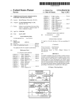
FIG. 1 is a simpli?ed block diagram of a process control
monitoring system including a ?eld device con?gured for
Wireless communication.
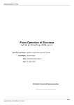
FIG. 2 is a block diagram of a process controller monitor
The present invention relates to industrial process control
or monitoring systems. More speci?cally, the present inven
tion relates to ?eld devices in such systems Which are capable
ing system in Which multiple ?eld devices transmit informa
of Radio Frequency (RF) communication.
tion to a remote meter.
In industrial settings, control systems are used to monitor
and control inventories of industrial and chemical processes,
including Wireless communication circuitry for communicat
FIG. 3 is an exploded cut aWay vieW of a ?eld device
and the like. Typically, the control system performs these
functions using ?eld devices distributed at key locations in the
industrial process and coupled to the control circuitry in the
control room by a process control loop. The term “?eld
device” refers to any device that performs a function in a
ing With a remote device such as a hand held unit.
20
distributed control or process monitoring system, including
all devices currently knoWn, or yet to be knoWn, used in the
measurement, control and monitoring of industrial processes.
FIG. 6 is a graph of voltage versus time as measured across
Some ?eld devices include a transducer. A transducer is 25
understood to mean either a device that generates an output
a capacitor shoWn in FIG. 5.
FIG. 7 is an electrical block diagram of circuitry for pro
viding Wireless communications in a process controller moni
toring system.
signal based on a physical input or that generates a physical
output based on an input signal. Typically, a transducer trans
forms an input into an output having a different form. Types of
transducers include various analytical equipment, pressure
sensors, thermistors, thermocouples, strain gauges, ?oW
FIG. 4 is a diagram of a process controller monitoring
system Which includes a ?eld device for Wireless communi
cation Which scavenges poWer from the process control loop.
FIG. 5 is a more detailed schematic diagram of circuitry
shoWn in FIG. 4.
DETAILED DESCRIPTION
30
The present invention provides a ?eld device con?gured to
couple to a process control loop Which further includes a
transmitters, positioners, actuators, solenoids, indicator
lights, and others.
Wireless communication module for one Way or bi-direc
tional Wireless communication. The Wireless communication
Typically, each ?eld device also includes communication
circuitry that is used for communicating With a process con
trol room, or other circuitry, over a process control loop. In
35
some installations, the process control loop is also used to
deliver a regulated current and/ or voltage to the ?eld device
for poWering the ?eld device. The process control loop also
carries data, either in an analog or digital format.
Traditionally, analog ?eld devices have been connected to
the control room by tWo-Wire process control current loops,
40
With each device connected to the control room by a single
tWo-Wire control loop. Typically, a voltage differential is
maintained betWeen the tWo Wires Within a range of voltages
45
control room by modulating the current running through the
50
majority of ?eld devices are hardWired to a process control
room and do not use Wireless communication techniques.
monitoring system 10 in Which a control room or control
system 12 couples to a ?eld device 14 over a tWo-Wire process
antenna 26.
Currently, industrial instrumentation often includes a local
display or “meter” Which can be used for local monitoring of
process information. The meter can be quite useful in many
alternative, the process control loop can carry digital signals
used for communication With ?eld devices.
In some installations, Wireless technologies have begun to
be used to communicate With ?eld devices. For example,
completely Wireless installations are used in Which the ?eld
device uses a battery, solar cell, or other technique to obtain
poWer Without any sort of Wired connection. HoWever, the
ered With poWer received from the tWo-Wire process control
loop, or can be poWered With poWer received from the process
control loop and stored for subsequent use. The module can
be a removable module in Which the module need only couple
to those ?eld devices in Which Wireless communication is
desired.
FIG. 1 is a simpli?ed block diagram of a process control or
control loop 16. The ?eld device 14 includes I/O poWer cir
cuitry 18, actuator/transducer 20 and Wireless communica
tion circuitry 22. The Wireless communication circuitry 22 is
con?gured to send and/or receive an RF signal 24 using an
from 12-45 volts for analog mode and 9-50 volts for digital
mode. Some analog ?eld devices transmit a signal to the
current loop to a current proportional to the sensed process
variable. Other analog ?eld device can perform an action
under the control of the control room by controlling the mag
nitude of the current through the loop. In addition to, or in the
module can transmit and/or receive an RF signal from a
remote device or location. The module can be directly poW
55
installations, hoWever, such a local display con?guration does
have several limitations. A local display requires direct visual
access to the ?eld device. Further, typically an operator can
only vieW a single meter at a time. The instruments Which
contain the meter are often not at a convenient location or
vieWing angle. One technique Which has been used to address
60
such a con?guration is the use of a meter Which is Wired to a
process transmitter. This alloWs the meter to be mounted at a
more convenient location. Another technique is shoWn and
SUMMARY
described in US. patent application Ser. No. 10/128,769,
?led Apr. 22, 2002, entitled PROCESS TRANSMITTER
A ?eld device for use in an industrial process control or 65 WITH WIRELESS COMMUNICATION LINK.
monitoring system includes terminals con?gured to connect
With the present invention, an RF communication module
to a tWo-Wire process control loop con?gured to carry data
is included in a ?eld device Which can be used in addition to
US 7,956,738 B2
3
4
the connection to a process control loop such as loop 16. The
Wireless communication module 22 can be con?gured to be
compact and loWer poWer such that it can be easily included
can be con?gured to provide a desired radiation pattern of RF
signals generated by antenna 26. For example, it may be
desirable to have the RF transmission be directional in some
implementations, or omnidirectional in others. In other
in existing ?eld device con?gurations. The module can be
example using a manual input such as buttons available to an
operator. The display 32 can be placed at a ?xed location or
can be a portable device such that it can carry throughout the
implementations, the cover 62 can be lengthened to provide
an additional interior cavity for placement of Wireless com
munication circuit 22.
The Wireless communication circuitry 22 can be selected
as desired. One example circuit is the “I-Bean” transmitter
device available from Millennial Net. HoWever, other cir
cuitry can be used. Analog or digital signals carried on pro
cess control loop 16 can be read and transmitted using the
Wireless communication circuit 22 Without disrupting opera
tion of the process control loop 16 or ?eld device circuitry 68.
The circuitry used for Wireless transmission should be sul?
process control system to monitor and observe operation of
various ?eld devices. Depending on the strength of the RF
signal 24 and the sensitivity of the transmit and receive cir
poWer constraints of process ?eld devices. Some prior art
transmitters are con?gured to receive an optional display
used for Wireless transmission of information for use in moni
toring control and/ or display of data. Such a radio transmitter
can make the ?eld device information available in a local area.
For example, a single local display such as display 32 can be
provided and used to display information from the ?eld
device 14. The display 32 can be con?gured to display infor
mation from several devices, either simultaneously, sequen
tially, or through commands provided to the display, for
ciently small and loW poWered to ?t Within the physical and
arranged generally in the position shoWn for Wireless com
cuitry, the area covered by the RF transmission can be con
trolled as desired. For example, FIG. 2 is a simpli?ed diagram
20
of a process control system 50 in Which a number of ?eld
devices 14 are coupled to the control room 12 through indi
vidual process control loops 16. Each ?eld device 14 trans
mits an RF signal 24 for receipt by display 32. In this example,
display 32 is capable of displaying four process variables
(PV1, PV2, PV3 and PV4) Which are received from the ?eld
devices 14 using antenna 52.As mentioned above, the display
25
32 can be a ?xed display or can be a portable display, such as
a hand held unit. In this particular con?guration, the display
32 is illustrated as shoWing tWo process variables Which relate
to process pressure and tWo process variables Which relate to
30
process temperature. This alloWs the ?eld devices 14 to pro
35
played, or used to interrogate a ?eld device 14.
40
pressure transmitter 60 Which is one example of a ?eld device.
Pressure transmitter 60 couples to tWo-Wire process control
used. Some process control loops are con?gured to connect to
multiple ?eld devices such that the ?eld devices can commu
?eld device. In general, any type of information transmitted
45
on such process control loops, or available or generated inter
nally or received by a ?eld device, or otherWise used to
control a ?eld device or other type of information, can be
transmitted using the Wireless communication techniques of
differential pressure occurring in a process ?uid. The output
from the sensor 64 is provided to measurement circuitry 66
Which couples to ?eld device circuit 68. The ?eld device
circuit 68 implements aspects of the I/O poWer supply 18
shoWn in FIG. 1. The Wireless communication circuitry 22
transmissions are superimposed on the 4-20 mA signal for
nication one another or monitor transmissions from another
loop 16 and includes a transmitter housing 62. Process control
loop 16 couples to terminals 56 carried on terminal board 58.
A pressure sensor 64 provides one example of a transducer
and is con?gured to couple to a process ?tting to measure a
4-20 mA current loops in Which a analog current level is
varied betWeen 4 and 20 mA to transmit information. The
same control loop can be used to provide poWer to the ?eld
transmission of additional information. Another example
tWo-Wire process control loop uses a protocol set forth by the
Instrument Society ofAmerica (ISA) Which is called the Field
Bus SP50 protocol. HoWever, end signaling protocol can be
capable of receiving an displaying information from that ?eld
device. An optional user input 48 can be used to, for example,
select the format of the display, the process variable dis
FIG. 3 is a simpli?ed cutaWay partially exploded vieW of a
Wireless circuitry 22 simply transmits an RF signal Which
couples directly to the process control loop 16 and transmits
an RF signal Which corresponds to any analog and/or digital
signals carried on the loop 16.
In general, the process control loop discussed herein can
comprise any type of process control loop for use in industrial
process control and monitoring systems. Such loops include
device. Another type of process control loop is in accordance
With the HART® communication protocol in Which digital
vide information over the RF connection Within a desired
range, for example, Within a local area. For example, if the
display 32 is Within 40 meters of a ?eld device 14, it Will be
munication circuit 22 in FIG. 3. In such a con?guration, the
Wireless communication circuit 22 can be used in place of the
local display. In such a con?guration, the communication
50
the present invention. In another example, a hand held unit or
device used to con?gure ?eld devices can be carried into the
?eld by an operator. The operator uses the hand held device to
send or receive information to a ?eld device When the hand
held device is Within proximity of the ?eld device. This alloWs
couples to ?eld device circuit 68 and may, in some embodi
ments, couple to process control loop 16.
the operator to gather information or program a ?eld device
The housing 62 includes end caps 70 and 72 Which can be
screWed into the housing 62. End cap 72 includes an RF
Without having to physically couple to the device or the physi
cal process control loop.
55
transparent WindoW 74 con?gured to align generally With an
In some embodiments, it is also desirable for communica
antenna 26 carried on Wireless communication circuit 22.
tions from a ?eld device, or to a ?eld device, to carry address
When attached, the end caps provide a intrinsically safe
enclosure for circuitry Within transmitter 60. The materials
typically used in end caps, for example metal, are not trans
parent to RF signals. HoWever, RF transparent WindoW 74
ing information. The addressing information can be indica
tive of the source of the transmission or the intended recipient
60
can transmit continuously or on a periodic or intermittent
basis, as desired. In another example, the Wireless communi
alloWs RF signals to be sent from or received by antenna 26.
One example RF transparent material for use With WindoW 74
is glass or the like. HoWever, any appropriate material can be
used. The WindoW and housing con?guration can help to meet
intrinsic safety requirements and provide ?ame proof (explo
sion proof) capability. Further, the cavity Within housing 62
of the transmission. The Wireless communication circuitry
cation circuitry only transmits When activated or “polled”.
The activation can be from a source internal to the ?eld
65
device, received through the process control loop, received
from a Wireless source, or received or generated by another
source. In environments in Which multiple ?eld devices may
US 7,956,738 B2
5
6
transmit simultaneously, the transmission protocol should be
from the process control loop 16. The bypass 112 alloWs loop
16 to operate normally and is connected in series With loop
16. Communication circuit 122 includes circuitry for receiv
ing information, analog and/ or digital information, carried on
selected to avoid or address any type of collisions Which
might interfere With the transmissions. For example, different
frequencies or frequency skipping techniques can be used,
random or semi-random transmission WindoWs can be used,
repeated transmissions or token based techniques can be
implemented or other collision avoidance techniques as
process control loop 16. The circuit 122 can responsively
transmit an RF signal 106 based upon the received informa
tion. If operated as a receiver, circuitry 122 is capable of
modulating data onto the electrical current carried in the loop
16. This can be either analog or digital information. This
desired. If the transmission includes error detection or cor
rection information, this information can be used to detect an
error in the transmission and/or correct any errors in the
transmissions. If an error is not correctable, the receiving unit
can request a re-transmission of the corrupt data or, can indi
con?guration alloWs data to be relayed over a Wireless com
munication netWork. The netWork canbe con?gured in accor
dance With any type of topology, including point to point,
cate an error, or can Wait for a subsequent transmission of the
spoke and hub and mesh topologies. Process device 104 can
be positioned at any location along the loop including con
data, or take other steps as desired.
FIG. 3 also shoWs an example hand held device 80 for
communication With circuitry 22 over RF connection 82.
Hand held device 80 includes a display 84 and user input 86.
Other types of inputs and outputs canbe included in hand held
device 80. Preferably, the hand held device 80 is battery
operated and can be carried into the ?eld by an operator for
communication With ?eld device 60. Information from the
?eld device 60, or from other sources, is displayed on display
84 and the hand held device is controlled using input 86.
Commands or other information can be transmitted by the
hand held device 80 to ?eld device 60.
In one con?guration, the Wireless communication circuitry
requires poWer Which is Within the poWer constraints avail
?gured as an individual device such as that illustrated in FIG.
4. In some installations, the ?eld device 104 should be ?eld
hardened and con?gured for intrinsically safe operation. The
20
device 104 can also be positioned Within another ?eld device
14, as part of a junction box 102, or even located Within the
control room Which houses control system 12. The ?eld
device 104 can connect to more than one RF circuit 122
and/or more than one process control loop 16, either simul
taneously or through the use of multiplexers or other tech
25
niques.
The use of a super capacitor alloWs the device to operate
Without internal batteries or other techniques. The use of a
able in the ?eld device. For example, one display currently
capacitor alloWs quick charging and the storage of su?i
used Within ?eld devices uses 3.6 volts at 0.5 mA. If a trans
ciently large energy potentials. When used in a haZardous
environment, large energy storage may not be acceptable in
order to meet intrinsic safety standards. HoWever, the process
mitter Which is capable of operating an LCD meter is
30
employed, the Wireless communication circuitry can replace
the LCD meter and use the same poWer source that is used to
drive the LCD meter. In another example, the Wireless com
munication circuitry is poWered directly from the process
control loop, for example using the voltage developed across
35
device 104 can be moved aWay from the hazardous environ
ment, such as at the junction box 102, Where intrinsic safety is
not required.
FIG. 5 is a simpli?ed schematic diagram of ?eld device 104
a diode drop connected in series With the process control loop.
shoWing super capacitor 114 in greater detail. In this example,
In embodiments in Which no battery is used With the commu
nication circuitry, the circuitry can more easily meet intrinsic
super capacitor 114 comprises two 10 Farad capacitors con
?gured to each carry a 2.5 volt potential. This yields an
equivalent capacitance of 5 farads With a 5 volt potential drop.
Assuming that the Wireless communication circuit 122 is
capable of operating at a voltage of betWeen 4 and 5 volts, the
available energy from each of the 5 Farad capacitors is 1/2*C
safety or other safety approval requirements and provide an
inde?nite ?eld life Without battery replacement or mainte
nance. In con?gurations in Which the Wireless con?guration
40
is only for sending information, poWer requirements can be
(Vl-2—VF2) Which is l/2*5*(52—42):22.5J.
reduced. In another example, if a greater transmission range is
desired, a stationary device such as display 32 as illustrated in
FIG. 6 is a graph of voltage versus time measured across
FIG. 1 can include an RF repeater for re-transmission of data
received from, or sent to, a ?eld device. The RF repeater can
be loop poWered, or can derive its poWer from other sources.
Further, once the RF data is received, it can be reformatted for
transmission over other medium, for example an Ethernet
45
connection, into existing data transmission structures used
50
Within process control systems, over an extended range RF
communication link such as a cell phone, or relaying using
another technique.
FIG. 4 is a simpli?ed diagram of a process controller or
monitoring system 100 Which illustrates another aspect of the
55
a control system 12 through process control loop 16 through
60
Process device 104 includes a poWer regulator 110, a shunt
or bypass 112, and a super capacitor 114. During operation,
capacity in a time tc:0.6J/0.02W:30s. Therefore, such a con
?guration Will be capable of transmitting a signal having a 1
second duration every 30 seconds. Assuming that the band
to be completely poWered by poWer received from the process
control loop 16.
the super capacitor 114 is sloWly charged (trickle charged)
using a poWer regulator 110 by using excess voltage tapped
volts of voltage drop. Assuming only 5 volts is available for
charging the super capacitor 114, and that the process control
loop is operating at a loW current level (i.e., 4 mA), there is
still 20 mW available to charge the super capacitor 114.
Because only 0.6 I Was consumed during the transmit cycle,
the available 20 mW Will charge the super capacitor to full
present invention. In system 100, a ?eld device 14 connects to
junction box 102. In the embodiment of FIG. 4, a ?eld device
104 couples to the process control loop 16 and includes Wire
less communication circuitry 122. The Wireless communica
tion circuitry 122 is con?gured to send an RF signal 106 and
super capacitor 114. In this example, 600 mW Wireless trans
mitter Which transmits a burst signal for a period of td of 1
second Will require 0.6J/S*ls:0.6J of energy. Thus, there is
ample energy available for operation of such a communica
tion circuit 122.
A typical poWer supply used to provide poWer to a process
control loop provides 24 volts DC. HoWever, in a 4-20 mA
system, a transmitter may only require 12 volts to operate.
Wiring losses in the process control loop may cause 2 to 4
65
Width of the communications signal is 200 Kb/ s and a packet
siZe of 200 b, the burst time is reduced to one millisecond and
the resulting transmit time is 0.03 seconds. In such a con?gu
ration, diagnostic data can easily be transmitted because it is
not of a time critical nature. HoWever, if suf?ciently fast
US 7,956,738 B2
7
8
charge times are available, control and process variable sig
?gured to receive a separate digital chip select signal (CS2)
nals can also be transmitted Wirelessly.
Although a super capacitor is described, any energy stor
age device can be employed including a battery, or other. The
energy that is used to charge the storage device can be elec
from microprocessor 224. Both the HART® circuit 230 and
the RF circuit 232 are con?gured to communicate With the
microprocessor 224 on an SCI bus, depending on Which chip
trical or magnetic and can be derived or collected from any
select is active. Microprocessor 224 is also con?gured to
provide a shut doWn signal to operational ampli?er 222.
source.
Microprocessor 224 includes a memory 236 Which is used for
storing programming instructions, temporary and permanent
FIG. 7 is a simpli?ed diagram of process controller moni
toring system 150 Which includes a control room 152 coupled
to a ?eld device 154 through tWo-Wire process control loop
variables and other information and may include both volatile
and non-volatile memory. The memory can include, for
example, an EEPROM and can contain addressing informa
156. Process control loop 156 extends across an intrinsic
safety barrier 158. The control room 152 is modeled as
including a poWer supply 160 and a load resistance 162.
The ?eld device 154 can be of any con?guration and is not
limited to the speci?c schematic shoWn in FIG. 7. RF com
tion Which uniquely identi?es circuitry 170. RP circuit 232
couples to an antenna 240 Which can be con?gured as an
internal antenna, external antenna, or combination, as
desired. Circuitry 170 is con?gured to couple across the tWo
Wire process control loop 156 such that the loop 156 can
munication circuitry 170 is shoWn coupled in series With loop
156. Circuitry 170 can be implemented in a terminal block of
a ?eld device. For example, circuitry 170 can be con?gured as
an add on module such that the tWo-Wire process control loop
156 can connect to existing transmitter circuitry.
terminate at another ?eld device such as a process transmitter
or process controller.
20
The circuitry 170 illustrated in FIG. 7 can be implemented
on a single printed circuit board such that RF antenna 240 is
formed integral With the board. This con?guration alloWs the
circuitry 170 to be easily implemented in existing ?eld
In the con?guration illustrated in FIG. 7, the communica
tion circuitry 170 enables Wireless communication abilities to
be added to a neW or existing process control loop or ?eld
devices and does not require the use of an external antenna.
device. The circuitry is con?gured to be poWered by the
This reduces installation complexity.
process control loop and can be installed anyWhere in the loop
25
ranging from the control room, anyWhere along the loop
itself, in the intrinsic safety (IS) barrier or junctionbox 158, as
sensed digital signal, the HART® circuitry 230 can control
operation of the RF transmit/receive circuit 232 for transmis
a stand alone ?eld device, or included in another ?eld device.
The circuitry can be con?gured for any type of communica
tion. HoWever, in one simple con?guration, the circuit 170 is
The optional HART® transmit/receive circuit 230 can be
used to monitor digital signals, such as a process variable,
carried on the process control loop 156. Based upon the
30
sion of information related to the sensed process variable, or
loop 156 and transmit an output related to the measured
other information. If the HART® circuitry is implemented in
accordance With the complete HART® protocol and appro
current to a Wireless receiver.
priate RF protocol stacks, the circuitry can implement gate
con?gured to measure the current carried in process control
Turning noW to one speci?c embodiment of circuitry 170
shoWn in FIG. 7, a sense resistance 180 and a poWer supply
35
diode 182 couple in series With process control loop 156. The
sense resistance 180 can be, for example, 10 ohms and is used
in sensing the current level I carried in the process control
loop 156. A test diode 184 is also coupled in series With the
loop 156 and provides a test point 186. This can be used to
calibrate or characteristiZe a ?eld device coupled to circuitry
40
Which includes diode 192 connected as shoWn across diode
45
Which includes capacitor 198, input ?lter 200, regulator 202,
capacitor 204 and secondary ?lter 206. Secondary ?lter 206
includes capacitor 208 and resistor 210. The poWer supply
circuitry 196 generates a poWer supply voltage VDD relative
to a circuit ground for use by circuitry in measuring the loop
current and Wirelessly transmitting a resultant signal.
Although a speci?c poWer supply implementation is shoWn,
any appropriate poWer supply con?guration or embodiment
the process control loop in order to exchange information
With the ?eld device. This alloWs the operator to repair equip
ment and do preventive maintenance on the equipment. The
Wireless communication con?guration set forth herein alloWs
the operator to interrogate ?eld devices Which may be in
locations Which are dif?cult to access. Further, even in con
?gurations in Which the ?eld devices are easily accessible, the
Wireless communication circuitry does not require an opera
50 tor to remove covers on equipment such as transmitters or
junction boxes in order to expose loop Wiring for physical
connection to the process control loop. This can be particu
larly bene?cial in haZardous locations Where explosive gases
may be used as desired.
In this embodiment, input circuitry 218 includes sense
munication With a ?eld device for monitoring, con?guration,
diagnostics, or exchange of other information or data.
Frequently, in process control or monitoring installations,
an operator is required to physically access a ?eld device or
170. An intrinsic safety protection circuit 190 is provided
182 and isolation resistors 194 connected at opposed ends of
sense resistance 180. Diode 182 is part ofa poWer supply 196
Way level functionality Which Will alloW a HART® master to
communication in a bi-directional manner through the RF
HART® gateWay device With a HART® capable ?eld device
on the process control loop 156. This alloWs Wireless com
55
or vapors may be present. A digital or analog process variable
can be sensed by the Wireless communication circuitry and
resistance 180 and is con?gured to measure the current I
transmitted to a Wireless meter or hand held device as dis
?oWing through loop 156. Input circuitry 218 also includes a
cussed above.
?lter 220 Which provides a differential connection to an OP
During operation, circuit 170 is placed in series With the
amp 222. The OP amp provides an ampli?ed input signal to an
analog to digital converter 226 Which is illustrated as part of
a microprocessor 224. A clock circuit 228 is provided and
process control loop 156 Where it utiliZes the 4-20 mA current
60
employ a common electrical ground, circuitry 170 can be
used to provide a clock signal to, for example, microprocessor
inserted on the high voltage side of the loop connection. This
con?guration alloWs access to other bus circuitry Within the
222. Optional HART® transmit and receive circuit 230 con
nects to microprocessor 224, loop 156, clock circuit 228 and
an RF transmit/receive circuit 232. The optional HART®
circuit 230 is con?gured to receive a digital chip select signal
(CS1) from microprocessor 224. The RF circuit 232 is con
?oWing through the loop to poWer itself. For ?eld devices that
65
?eld device such as a CAN interface. The con?guration
includes a test connection 186 for use in measuring loop
current during testing. The sense resistance 180 is preferably
con?gured to provide an equivalent of capacitance of Zero as
US 7,956,738 B2
10
measured at terminals 181 Which connect to loop 156 in
range of about 200 feet, hoWever other ranges can be achieved
accordance With intrinsic safety standards. Circuitry 170 is
con?gured for nominal operation at betWeen 3 and 4 volts and
using different poWer requirements, circuit sensitivity,
the Zener diode 182 along With sense resistance 180 sets this
mounted in a metal enclosure, such as a ?eld housing com
operating voltage. The excess voltage available on typical
4-20 mA current loop is su?icient to operate circuitry 170.
Further, poWer management techniques can be employed to
limit the current draWn from the loop to about 3 mA. This
alloWs any ?eld device connected to the process control loop
to send an alarm level signal of 3.6 mA Without collapsing the
circuit by draWing more than the available current level.
partment of a transmitter, an RF transparent portion of the
housing should be used to alloW transmission and reception of
signals from antenna 240. For example, as discussed above, a
glass WindoW can be used. Other example materials include
any material Which is suf?ciently transmissive to RF signals
including plastic, or other materials.
The addition of the optional HART® circuitry 230 alloWs
Zener diode 182 acts as a shunt element Which is placed in
the circuitry 170 to selectively listen to a HART® message on
the 4-20 mA signal carried on the current loop 156. Informa
antenna con?guration, and the like. If the circuitry 170 is
series With the loop 156 to develop a preregulated voltage on
the input ?lter stage. Any portion of the loop current Which is
tion such as measured process variables, diagnostic informa
not used by circuitry 170 is shunted through Zener diode 182.
The input ?lter 200 can comprise capacitive, inductive and
resistive elements and is used to isolate the loop from any
noise or load ?uctuation generated by circuitry 170. This also
suppresses noise in the HART® extended frequency band in
tion, or other information can be transmitted to a Wireless
order to conform With HART® standards.
receiver. Further, if the HART® circuitry 230 is con?gured to
modulate a digital signal onto the process control loop, it can
be used to remotely command or interrogate a ?eld device
coupled to the loop 156. For example, the HART® circuitry
20
The voltage regulator 202 can be any appropriate voltage
230 can be con?gured to act as a secondary master on the 4-20
mA current loop. This, in conjunction With RF circuitry 232
regulator such as, but not limited to linear or sWitch mode
con?gured as a full transceiver, enables bi-directional com
regulators and is used to supply the voltage VDD to the cir
munication and con?guration of ?eld device from a Wireless
master unit, for example a hand held device 80 shoWn in FIG.
3.
Microprocessor 224 can also preferably be used to imple
cuitry. Filter 206 is used to store energy and further decouples
circuit loads from the regulator 202. The output voltage of the
secondary ?lter 206 is alloWed to sag by several hundred
millivolts during circuit load changes. This alloWs peak cur
rent draWs by the circuitry 172 to be averaged from the 4-20
mA current loop.
In this embodiment, the microprocessor 224 including A/D
converter, along With the RF circuitry 232 and input circuitry
25
30
techniques and can be transmitted to a remote location, either
Wirelessly, or using the HART® transmission capabilities
provided by circuitry 230, or by setting the current level
218 can be placed into a sleep mode or loW poWer mode
during periods of idle operation in order to reduce poWer
drain. For example, at a selected interval such as every 10
seconds, an internal timer in the microprocessor can enable
carried on loop 156 to an alarm value or other pre-determined
35
value.
Circuitry 170 is preferably con?gured to alloW operation in
the measurement of the loop current by the A/D converter.
The measurement circuitry is alloWed to settle before the A/D
conversion occurs. After the A/D conversion is completed,
both the loop measurement circuitry and the A/ D converter
are turned off to conserve poWer. The microprocessor passes
ment diagnostics functionality. Microprocessor 224 is con
?gured to monitor the voltage and current characteristics of
the process control loop 156, improper or problematic varia
tions in current and voltage can be identi?ed using diagnostic
haZardous locations and to meet the appropriate approval and
speci?cations, such as intrinsic safety standards. For
example, the intrinsic safety protection 190, along With
40
intrinsically safety rated resistor 180 is used on the input to
the measured value to the RF circuitry 232 for transmission.
the circuitry 170. Using appropriate components and circuit
Upon completion of the transmission, the microprocessor and
layout, the addition of a redundant Zener diode 192 in parallel
With Zener 182 provides a level of redundancy and limits the
RF circuitry return to the loW poWer mode until the next cycle.
The microprocessor may even put itself to sleep temporarily
to save poWer. Using these poWer management techniques,
the microprocessor is able to manage overall current require
ments of the circuit by staggering the load demands on the
amount of voltage that can enter this circuit in an intrinsic
45
170 and snub any discharge of stored energy from the circuit
regulator stage.
through its external terminals. This provides an equivalent
capacitance of substantially Zero. The loop measurement cir
Loop current measurement is achieved using the 10 ohm
sense resistor 180 coupled in series With the 4-20 mA current
50
loop 156 to measure the analog current level. The voltage
developed across the sense resistor 180 is ?ltered to remove
55
the A/ D converter 226 of microprocessor 224.
The RF circuitry 232 can be any appropriate circuitry or
con?guration as desired. In one simple form, the RF circuitry
232 simply transmits a measured variable to a Wireless
receiver. The antenna 240 can be used to broadcast the RF
cuitry is further protected by tWo intrinsic safety rated high
value resistors 194 connected betWeen the tWo ends of the
sense resistor 180 and the ?lter 220. Other circuit components
can be protected from any outside energy sources by the use
of potting material or the like Which also prevents haZardous
?uctuations due to HART® digital communications as Well
as any loop noise. An operational ampli?er stage 222 pro
vides further signal conditioning and the signal is passed to
safety protected system. Similarly, the sense resistor 180 can
be used to limit the maximum current that can enter the circuit
gases and vapors from reaching any internal storage elements
and nodes in the circuitry 170. For other non-haZardous loca
tions, intrinsic safety components may not be required.
The term “?eld device” as used herein can be any device
Which is used in a process controller monitoring system and
60
signal and can be formed integral With the circuitry 170, for
does not necessarily require placement in the “?eld.” The
of a circuit board. The RF circuitry 232 can, in some embodi
ments, include a Wireless receiver such that the circuitry 232
device can be located anyWhere in the process control system
including in a control room or control circuitry. The terminals
used to connect to the process control loop refer to any elec
trical connection and may not comprise physical or discrete
can be con?gured as a transceiver. The same antenna 240 can 65
terminals. Any appropriate radio frequency communication
be used for both transmission and reception if desired. A
typical loW poWered transceiver may have a communication
munication protocol, frequency or communication tech
example in the form of traces routed around an outside edge
circuitry can be used as desired as can any appropriate com
US 7,956,738 B2
11
12
nique. The power supply circuitry is con?gured as desired and
8. The apparatus of claim 1 Wherein the Wireless commu
is not limited to the con?gurations set forth herein. In some
embodiments, the ?eld device includes an address Which can
be included in any RF transmissions such that the device can
be identi?ed. Similarly, such an address can be used to deter
nication circuitry includes intrinsic safety protection cir
cuitry.
9. The apparatus of claim 1 Wherein the Wireless commu
nication circuitry includes an analog to digital converter con
mine if a received signal is intended for that particular device.
HoWever, in other embodiments, no address is utiliZed and
data is simply transmitted from the Wireless communication
circuitry Without any addressing information. In such a con
?guration, if receipt of data is desired, any received data may
not include addressing information. In some embodiments,
?gured to provide a digital representation of current ?oWing
through the tWo Wire process control loop.
10. The apparatus of claim 8 Wherein the RF signal is based
upon the sensed current.
11. The apparatus of claim 1 Wherein the Wireless commu
nication circuitry includes a microprocessor.
this may be acceptable. In others, other addressing techniques
12. The apparatus of claim 1 Wherein the Wireless commu
or identi?cation techniques can be used such as assigning a
particular frequency or communication protocol to a particu
lar device, assigning a particular time slot or period to a
particular device or other techniques. Any appropriate com
munication protocol and/or networking technique can be
employed including token-based techniques in Which a token
is handed off betWeen devices to thereby alloW transmission
or reception for the particular device.
Although the present invention has been described With
reference to preferred embodiments, Workers skilled in the art
Will recogniZe that changes may be made in form and detail
Without departing from the spirit and scope of the invention.
As used herein, Radio Frequency (RF) can comprise electro
magnetic transmissions of any frequency and is not limited to
a particular group of frequencies, range of frequencies or any
other limitation. Any communication protocol can be used, as
desired, including IEEE 802.1 lb, 802.154, or other protocols,
including proprietary communication protocols.
nication circuitry includes a memory containing addressing
20
information.
13. The apparatus of claim 1 Wherein the Wireless commu
nication circuitry includes an antenna.
14. The apparatus of claim 1 Wherein the Wireless commu
nication circuitry is con?gured to receive an RF signal and
responsively transmit a signal on the tWo Wire process control
loop.
15. The apparatus of claim 1 Wherein the poWer supply
circuitry includes an electrical element comprises a Zener
diode con?gured to couple in series With the tWo Wire process
25
control loop.
16. The apparatus of claim 1 Wherein the poWer supply
circuitry includes a Wireless communication circuitry is con
?gured to enter a sleep mode during idle periods.
17. The apparatus of claim 1 including:
30
an energy storage capacitor con?gured to store an electrical
charge using poWer received from the tWo-Wire process
control loop; and
What is claimed is:
Wherein the poWer supply circuitry is con?gured to use
1. A process control transmitter for monitoring a process
variable in an industrial process comprising:
poWer from the electrical charge stored on the energy
storage capacitor.
a process variable sensor con?gured to sense the process 35
18. The apparatus of claim 1 Wherein the Wireless circuitry
variable;
I/O circuitry con?gured to couple to a tWo Wire process
control loop and communicate on the process control
is carried on a modular circuit board con?gured to mount in a
housing of the process variable transmitter.
loop;
Wireless communication circuitry coupled to the tWo Wire
process control loop con?gured to transmit an RF signal;
and
poWer supply circuitry coupled to the tWo Wire process
19. The apparatus of claim 1 Wherein the Wireless commu
40
series With the tWo-Wire process control loop.
20. The apparatus of claim 1 including:
an explosion proof housing con?gured to enclose the Wire
less circuitry;
an integral RF transparent region in the housing con?gured
control loop including a voltage regulator, the poWer
supply circuitry electronically connected in series With
the process control loop, the voltage regulator con?g
ured to receive a voltage drop and responsively provide
to alloW RF transmission therethrough.
21. The apparatus of claim 20 Wherein the RF transparent
region comprises glass.
a regulated voltage output to poWer the Wireless com
munication circuitry.
2. The apparatus of claim 1 including a terminal block
con?gured to electronically connect to the tWo Wire process
control loop and Wherein the Wireless communication cir
nication circuitry includes terminals con?gured to couple in
50
22. The apparatus of claim 20 including an end cap con
?gured to mount to a main housing and Wherein the end cap
includes the RF transparent region.
23. The apparatus of claim 1 including:
cuitry couples to the terminal block.
a circuit board con?gured to carry the Wireless communi
cation circuitry; and
3. The apparatus of claim 1 Wherein the Wireless commu
nication circuitry is completely poWered With poWer from the
55
tWo Wire process control loop.
4. The apparatus of claim 1 Wherein the Wireless commu
nication circuitry includes a resistor coupled in series With the
tWo Wire process control loop.
5. The apparatus of claim 1 including a battery con?gured
to poWer the Wireless communication circuitry.
6. The apparatus of claim 1 Wherein the Wireless commu
nication circuitry includes tWo Wire loop communication cir
cuitry con?gured to communicate on the tWo Wire communi
cations loop.
7. The apparatus of claim 1 Wherein the Wireless commu
nication circuitry includes HART® communication circuitry.
an RF antenna coupled to the Wireless communication
circuitry and carried on the Wireless communication
circuit board.
24. The apparatus of claim 19 Wherein the Wireless com
munication circuitry is integral With a terminal block Which
carries the terminals.
25. The apparatus of claim 1 Wherein the Wireless commu
nication circuitry is con?gured to transmit an RF signal
related to an analog current level carried through the process
loop.
65
26. The apparatus of claim 1 Wherein the Wireless commu
nication circuitry is con?gured to transmit an RF signal
related to a digital signal carried by the process control loop.
US 7,956,738 B2
14
13
coupled to the Wireless communication circuitry con?gured
46. The apparatus of claim 32 Wherein the RF circuit is
completely poWered With poWer from the tWo Wire process
to operate as a bi-directional HART® to RF gateway unit.
control loop.
27. The apparatus of claim 1 including a HART® module
28. The apparatus of claim 1 Wherein the Wireless commu
47. The apparatus of claim 32 including a resistor coupled
in series With the tWo Wire process control loop.
nication circuitry is con?gured for periodic communication.
29. The apparatus of claim 1 Wherein the Wireless commu
48. The apparatus of claim 32 including a battery con?g
nication circuitry is con?gured to transmit an RF signal
ured to poWer the RF circuit.
related to a process variable.
49. The apparatus of claim 32 including tWo Wire loop
communication circuitry con?gured to communicate on the
tWo Wire communications loop.
30. The apparatus of claim 1 Wherein the voltage regulator
comprises a linear regulator.
31. The apparatus of claim 1 Wherein the voltage regulator
comprises a sWitch mode regulator.
32. Radio frequency (RF) communication apparatus con
50. The apparatus of claim 32 including intrinsic safety
protection circuitry.
51. The apparatus of claim 32 including an analog to digital
converter con?gured to provide a digital representation of
current ?oWing through the tWo Wire process control loop.
52. The apparatus of claim 32 including a microprocessor.
?gured to couple to a ?eld device in a tWo-Wire process
control loop, comprising:
?rst and second electrical connections con?gured to couple
in series With the tWo-Wire process control loop;
a third electrical connection con?gured to couple to the
tWo-Wire process control loop, Wherein the second and
third electrical connections are con?gured to couple in
53. The apparatus of claim 32 including a memory con
taining addressing information.
20
parallel With the ?eld device; and
an RF circuit con?gured to receive poWer from the tWo
Wire process control loop through the ?rst and second
electrical connections and transmit an RF signal Which
contains information related to data carried on the tWo
25
Wire process control loop.
33. The apparatus of claim 32 Wherein the RF circuit is
con?gured to receive an RF signal Which contains incoming
data and further including circuitry con?gured to respon
sively transmit the incoming data on the tWo-Wire process
con?gured to enter a sleep mode during idle periods.
58. The apparatus of claim 32 including:
30
control loop.
an energy storage capacitor con?gured to store an electrical
charge using poWer received from the tWo-Wire process
control loop; and
34. The apparatus of claim 32 including a forth electrical
poWer supply circuitry con?gured to use poWer from the
electrical charge stored on the energy storage capacitor
connection and Wherein the third and forth electrical connec
tions are electrically coupled together.
35. The apparatus of claim 32 including an electrical ele
ment coupled betWeen the ?rst and second electrical connec
54. The apparatus of claim 32 including an antenna.
55. The apparatus of claim 32 Wherein the RF circuit is
con?gured to receive an RF signal and responsively transmit
a signal on the tWo Wire process control loop.
56. The apparatus of claim 36 Wherein the electrical ele
ment comprises a Zener diode con?gured to couple in series
With the tWo Wire process control loop.
57. The apparatus of claim 32 Wherein the RF circuit is
35
to poWer the RF circuit.
59. The apparatus of claim 32 Wherein the RF circuit is
tions for use in communication on the tWo-Wire process con
carried on a modular circuit board con?gured to mount to the
trol loop.
?eld device the process variable transmitter.
36. The apparatus of claim 32 including an electrical ele
ment coupled betWeen the ?rst and second electrical connec
tions for use in providing poWer to the RF circuit.
40
circuit.
61. The apparatus of claim 60 Wherein the explosion proof
37. The apparatus of claim 36 including a voltage regulator
coupled to the electrical element Which provides a regulated
voltage output to the RP.
38. The apparatus ofclaim 32 including HART® commu
nication circuitry con?gured to receive information from the
tWo-Wire process control loop in accordance With the
HART® communication protocol.
39. The apparatus of claim 38 Wherein the information
contained in the RF signal comprises information received by
the HART® communication circuitry.
40. The apparatus of claim 32 including a microprocessor
coupled to the RF circuit con?gured to control the RF signal.
41. The apparatus of claim 32 Wherein the RF circuit is
con?gured to be added to an existing ?eld device.
42. The apparatus of claim 32 Wherein the RF signal carries
housing includes:
an integral RF transparent region in the housing con?gured
45
63. The apparatus of claim 61 Wherein the RF transparent
region comprises plastic.
50
64. The apparatus of claim 32 including:
a circuit board con?gured to carry the RF circuit; and
an RF antenna coupled to the RF circuit and carried on the
55
information related to an analog current level carried on the
60
process control loop.
44. The apparatus of claim 32 including a ?lter con?gured
to couple the RF circuit to the tWo-Wire process control loop.
45. The apparatus of claim 32 including a terminal block
con?gured to electronically connect to the tWo Wire process
control loop and Wherein the RF circuit couples to the termi
nal block.
to alloW RF transmission therethrough.
62. The apparatus of claim 61 Wherein the RF transparent
region comprises glass.
tWo-Wire process control loop.
43. The apparatus of claim 32 Wherein the RF signal carries
information related to a digital signal carried on the tWo-Wire
60. The apparatus of claim 32 including:
an explosion proof housing con?gured to enclose the RF
circuit board.
65. The apparatus of claim 32 including a HART® module
coupled to the RF circuit con?gured to operate as a bi-direc
tional HART® to RF gateWay unit.
66. The apparatus of claim 32 Wherein the RF circuit is
con?gured to transmit an RF signal related to a process vari
able.
67. The apparatus of claim 32 including a directional
antenna coupled to the RF circuit.
68. The apparatus of claim 32 Wherein the RF signal
includes error correction information.
65
69. The apparatus of claim 32 Wherein the RF signal is in
accordance With a topology selected from the group of
topologies consisting of point to point, spoke and hub, and
mesh topologies.
US 7,956,738 B2
16
15
70. The apparatus of claim 32 including a digital chip
responsive to a chip select signal.
83. The method of claim 78 Wherein the ?rst and third
electrical connections are electrically coupled together.
84. The method of claim 78 including using an electrical
element coupled betWeen the ?rst and second electrical con
71. The apparatus of claim 32 including a shunt element
con?gured to shunt electrical current from the tWo-Wire pro
cess control loop.
72. The apparatus of claim 32 including loop communica
tion circuitry coupled to the third electrical connection.
73. The apparatus of claim 72 including a microprocessor
coupled to the loop communication circuitry.
74. The apparatus of claim 73 Wherein the microprocessor
nections for use in communication on the tWo-Wire process
control loop.
10
is coupled to the RF circuit.
75. The apparatus of claim 32 including poWer supply
circuitry connected in series With the ?rst and second electri
cal connections.
76. The apparatus of claim 75 Wherein the poWer supply
85. The method of claim 78 including using an electrical
element coupled betWeen the ?rst and second electrical con
nections for use in providing poWer to the RF circuit.
86. The method of claim 78 including coupling an RF
circuit to an existing ?eld device.
87. The method of claim 78 Wherein the RF signal carries
information related to an analog current level carried on the
tWo-Wire process control loop.
88. The method of claim 78 Wherein the RF signal carries
circuitry includes a linear voltage regulator.
information related to a digital signal carried on the tWo-Wire
77. The apparatus of claim 75 Wherein the poWer supply
circuitry includes a sWitch mode voltage regulator.
process control loop.
89. The method of claim 78 including completely poWer
ing RF circuitry With poWer from the tWo Wire process control
78. A method for RF communicating With a tWo-Wire pro
cess control loop, comprising:
connecting ?rst and second electrical connections in series
to the tWo-Wire process control loop and a ?eld device;
connecting a third electrical connection to the ?eld device;
alloWing electrical current from the tWo-Wire process con
trol loop to How from the ?rst connection through the
second connection and through the electrical third con
nection to the ?eld device;
transmitting an RF signal Which contains information
20
90. The method of claim 78 including storing addressing
information in a memory.
91. The method of claim 78 including placing RF circuitry
in a sleep mode during idle periods.
25
92. The method of claim 78 including providing a bi
directional HART® to RF gateWay.
93. The method of claim 78 including transmitting an RF
signal related to a process variable.
30
includes error correction information.
94. The apparatus of claim 78 Wherein the RF signal
related to data carried on the tWo-Wire process control
loop.
95. The apparatus of claim 78 Wherein the RF signal is in
accordance With a topology selected from the group of
79. The method of claim 78 Wherein the transmitting an RF
signal comprises transmitting RF data as a function of infor
mation received from the tWo-Wire process control loop in
accordance With the HART® protocol.
80. The method of claim 78 Wherein the transmitting com
topologies consisting of point to point, spoke and hub, and
mesh topologies.
35
prises digital communicating.
Wire process control loop.
97. The apparatus of claim 78 including regulating poWer
With a sWitch mode voltage regulator.
81. The method of claim 78 Wherein the transmitting com
82. The method of claim 78 including receiving an RF
mit the incoming data on the tWo-Wire process control loop.
96. The apparatus of claim 78 including providing a shunt
element con?gured to shunt electrical current from the tWo
prises analog communicating.
signal Which contains incoming data and responsively trans
loop.
40
*
*
*
*
*