1
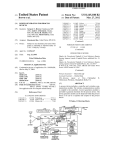
US008258654B2
(12) Ulllted States Patent
(10) Patent N0.:
Parsons
(54)
(45) Date of Patent:
5,586,048 A * 12/1996 Coveley ...................... .. 702/189
PORTABLE POWER SWITCHING
5,598,042 A
D381,632 S
.
.
.
5,650,771
Inventor:
(73)
Ass1gnee: Leviton Manufacturing Co., Inc.,
Kevin Parsons, W1lsonv1lle, OR (US)
_
Melville, NY(US)
A
1/1997 MIX er a1~
7/1997 Overthun
*
7/1997
~
.
~
~
~
-
5,673,022 A
9/1997 Patel
5,748,466 A
5/ 1998 McGivern et a1.
5,764,146 A *
6/1998 Baldwin et a1. ............. .. 340/567
4/1999 Paulus et a1.
A
5/1999
5,982,103 A
Mosebrook et a1.
11/1999 Mosebrook et a1‘
patent 15 extended or adjusted under 35
6 078 253 A *
6/2000 Fowler ““““““““““““ “ 340/501
USC 15402) by 172 days-
6,380,852 B1
4/2002 Hartman etal.
(21) Appl. N0.: 12/503,3s1
Filed:
............................. .. 340/656
9/1997 Holcomb et a1‘
5,905,442
Subject‘ to any dlsclalmer, the term ofthls
Lee
5,670,940 A
5,898,407 A
*
( ) Notlce.
(Commued)
Jul- 15, 2009
FOREIGN PATENT DOCUMENTS
KR
(65)
20-1998-0041190
Prior Publication Data
US 2011/0012433 A1
(51)
Sep. 4, 2012
WIRELESS OCCUPANCY SENSING WITH
(75)
(22)
US 8,258,654 B2
Int- ClH01H 35/00
9/1998
(Continued)
Jan. 20, 2011
OTHER PUBLICATIONS
U.S. Appl. No. 12/434,543, ?led May 1, 2009, not yet published, 23
pages,
(2006.01)
(52)
US. Cl.
(58)
Field of Classi?cation Search ................ .. 307/117,
..................................................... .. 307/116
_
(Commued)
307/116
.
See application ?le for complete search history.
.
d
Prlmary Exammer i Jare Fureman
Assistant Examiner * Adi Amrany
(56)
References Cited
(74) Attorney, Agent,
McCollom PC
or Firm * Marger Johnson &
US. PATENT DOCUMENTS
4,305,021 A *
12/1981 Schreiden ................... .. 315/159
2 i
,
galvln et a1~a1~~~~
,
ameron et
4,820,938 A
*
.
.
.... ..
Mix et a1‘ ' ' ' ' ' ' ' ' '
ABSTRACT
A portable switching device may include a Wireless receiver
~
~
-
' ' ' ' “ 307“ 17
to recelve'a W1reless slgnal from an occupancy sensor, and a
4,890,093 A 4.
121989 Allison et a1‘ “““““““ “ 340/567
poWer swltch to control poWer to a load 1n response to the
5,157,273 A
10/1992 Medendorp et a1‘
Wireless signal. In some embodiments, the Wireless signal
5,374,854 A * 12/ 1994 Chen ........................... .. 307/117
may include an occupancy signal that indicates the occupied
5,448,290 A
4/l989
(57)
~~~~ ~~
9/1995 vaflzeeland
2
state of a monitored space. In other embodiments, the Wire
223E531‘
less signal may include a detector signal that requires further
534893827 A
2/ 1996 Xia
5,534,850 A *
7/1996
processing to determine the occupied state of the space.
5,538,181 A
7/1996 Simmons et a1.
Lee ............................. .. 340/565
19 Claims, 7 Drawing Sheets
OCCUPANCY SENSOR
56
POWER SOURCE
S
58
m WW»)
DETECTOR |
SIGNAL
6i
64
63
PROCESSOR "'60
F --------- --~
USER
i DETECTOR i-'
H INTERFACE
PORTABLE SWITCHING DEVICE
P70
WIRELESS
RECEIVER
P72
_q
SIGNAL
PRocEssoR
P80
USER
INTERFACE
SWITCH CONTROL LOGIC
, ___________
1 POWER SWITCH
.............. -.
88
_>
US 8,258,654 B2
Page 2
U.S. PATENT DOCUMENTS
6,418,324
6,587,739
6,703,786
6,720,874
6,731,024
6,756,998
6,888,323
6,909,921
6,940,230
6,956,493
6,993,417
7,027,416
7,071,672
7,123,139
7,155,317
7,230,532
7,415,310
7,511,613
7,522,036
7,541,924
7,544,941
7,626,339
7,688,005
7,765,033
7,830,133
7,918,406
7,940,167
8,009,042
8,018,166
2002/0023233
2002/0135476
2003/0073342
2005/0030177
2005/0132408
2006/0125624
2007/0075852
2007/0132318
2007/0222584
2007/0272293
2007/0276548
2007/0290621
2008/0024007
2008/0068204
2008/0094210
2008/0111491
2008/0136663
2008/0176608
2008/0218099
2008/0303661
2009/0049466
2009/0101386
2009/0102679
2009/0135006
2009/0137163
2009/0195704
2009/0219245
2009/0278472
2010/0007801
2010/0207759
2010/0237711
2010/0237781
2010/0237783
2010/0277306
2010/0308664
2010/0315196
2011/0036699
2011/0074225
2011/0080529
2011/0090042
2011/0210622
2011/0282509
7/2002
7/2003
3/2004
4/2004
5/2004
6/2004
5/2005
6/2005
9/2005
10/2005
1/2006
4/2006
7/2006
10/2006
12/2006
6/2007
8/2008
3/2009
4/2009
6/2009
6/2009
12/2009
3/2010
7/2010
11/2010
4/2011
5/2011
8/2011
9/2011
2/2002
9/2002
4/2003
2/2005
6/2005
6/2006
4/2007
6/2007
9/2007
11/2007
11/2007
12/2007
1/2008
3/2008
4/2008
5/2008
6/2008
7/2008
9/2008
12/2008
2/2009
4/2009
4/2009
5/2009
5/2009
8/2009
9/2009
11/2009
1/2010
8/2010
9/2010
9/2010
9/2010
11/2010
12/2010
12/2010
2/2011
3/2011
4/2011
4/2011
9/2011
11/2011
Abrams et al. ................ .. 700/83
Tannenbaum
610-2008-010549
10-2009-0130800
Energy ConservationiHome and Of?ce, echo?ex, EnOcean Alli
ance, Oct. 20, 2008 (earliest suspected availability date extracted
from digital document), Squamish, BC, Canada, 41 pages.
Molnar et al.
.............. .. 307/147
Bilger
Null et al.
Bilger
Myron et al.
Youngblood
Osann, Jr.
................... .. 700/291
KriZ
Drusenthal
Sweeney
Tran ............................ ..
700/259
Albsmeier et al.
Bovee et al.
Wang
Preuss et al. ................ .. 340/531
Elwell
Gorman et al.
Paton
.......................... ..
315/155
Reid
Perry
.......................... .. 700/275
Williams et al.
Rosen
Steiner et al.
Steiner et al.
Soccoli et al.
Bach, DEMO of Self-Powered PIR Radio Sensor, Application Note
AN013, EnOcean, Jan. 2007, 8 pp.
User Reference Guide, 8 Outlet Power Strip with Personal Sensor,
IDP-3050-A version 2, Nov. 2007, Isole, WattStopper, Santa Clara,
CA, 4 pp.
Installation Instructions, 8 Outlet Power Strip with Personal Sensor,
IDP-3050-A version 2, Jan. 2008, ISOLe, WattStopper, Santa Clara,
CA, 8 pp.
Bach, Power Supply LayoutiLayout considerations for Line-Power
Supplies, Application Note 101, EnOcean, Jan. 20, 2009, 4 pp.
Bach, Motion SensoriDesign Example for an Ambient Light Pow
ered PIR, Application Note 306, EnOcean, Jan. 21, 2009 (earliest
suspected availability date extracted from digital document), 7 pp.
Frequently Asked Questions, Airwave, Ledalite, Mar. 1, 2009, 6 pp.
Technical Guide, Airwave, Ledalite, Mar. 5, 2009, 14 pp.
Airwave Speci?cation Overview, Airwave, Wireless by Ledalite,
Mar. 4, 2009, 2 pp.
Isole Plug Load Controls, WattStopper, Santa Clara, CA, Jan. 7,
2009, 8 pp.
Concept of a Occupancy Sensor Light Switch, Application Note
AN012, EnOcean, Sep. 2007, Germany, 2 pp.
Bach, Self-Powered PIR Radio Sensor starting at 40 lx, Application
Note AN013A, EnOcean, Aug. 2007, Germany, 4 pp.
Bach, Ambient light powered occupancy sensor for Indoor, Applica
tion Note, EnOcean, Dec. 2006, Germany, 3 pp.
Heath/Zenith Wireless Outdoor Power Control, Model 6022,
O’Meany
McKinney et al.
Geyer
Albsmeier et al.
Dahley et al.
HeathCo LLC, Bowling Green, KY, 2007, 20pp.
Ostrovsky et al. .......... .. 340/527
New Occupancy/Vacancy Sensor Sets a Higher Performance Stan
dard, Lutron Electronics Co., Inc., Coopersburg, PA, Jun. 9, 2009, 1
Schmidt et al.
Schmidt et al.
Albsmeier et al.
Schmidt
UZunovic et al.
page.
Black, Rich, Lutron RF Technology . . . Reliable, First, Forward
Thinking, Lutron Electronics Co., Inc., Coopersburg, PA, Aug. 2006,
15 pp.
Carmen et al.
Kropelin et al., APC UPS Daemon, “APCUPSDE User Manual,” Jul.
31, 2009, 111 pp.
Bulogics, “Home AutomationiLight, Your Way, Product Over
Paradiso et al. ............. .. 340/540
view,” 2008, 11 pp.Bulogics, Our Gadgets: USB Shutdown Stick,
Clarket a1.
................. .. 315/113
Budampati et al. ........... .. 307/19
Spira
Courtney et al.
Budampati et al. ......... .. 455/572
Newman
Chick
Schoettle et al.
Schoettle
Schoettle ................. .. 340/8 1 5 .4
Schoettle .................... .. 340/ 540
Schoettle
.................... .. 439/894
Bombara
Frankel et al.
Cooper et al.
Sloan et al. ................. .. 340/540
Parsons
Mar. 31, 2010, 1 page.
Bulogics, Our Gadgets: USB Shutdown Stick, Mar. 31, 2010, 1 page.
EMX Industries, “BlueGuard Bluetooth Enabled Stand-Alone
Access Control,” Cleveland, OH, May 6, 2009, 2pp.
Leviton, S1000/ S2000 Series, Leviton Surge Strips, “Quality Protec
tion. Everyday Application,” Product Info Sheet, May 10, 2010, 2 pp.
Leviton, TVSS Master Specs, Section 16478, Transient Voltage
Surge Suppression (Surge Protective Devices), May 10, 2010, 6 pp.
National Electrical Manufacturers Association, “NEMA Guide Pub
lication WD Jul. 20004Occupancy Motion Sensors,” 2000, 16 pp.
Northern Softworks, “Welcome to Northern Softworks,” Lights Out,
Mills et al. .................. .. 315/294
. 307/116
Dupre et al.
315/86
Dupre et al.
. 315/149
Leinen et al. ............ .. 340/539.3
Face et al. ................... .. 307/104
Dec. 15,2009, 1 page.
SmartHomeUSA, “Smart Strip, Power StripiUser’s Guide,” for
Models LCGl, LCG2, LCG3, LCG4, LCG5, Dec. 15, 2009, 4 pp.
SmartHomeUSA, “Smart Strip Power Strip with Coax, Fax &
Modem Protection,” Dec. 15, 2009, 5 pp.
Corn?eld Electronics, Inc., “How Does TV-B-Gone Work?,”2009, 1
page.
Leviton, “Infrared Repeater systemiComponent Speci?cations,”
Schmidt et al.
Part Nos. 47621-MIE, 47621-CMS, 47603-110, 2001, 2 pp.
U.S. Appl. No. 12/778,014, ?led May 11, 20 10, not yet published, 30
Delnoij et al. .............. .. 307/117
pages.
Wong
U.S. Appl. No. 12/649,697, ?led Dec. 30, 2009, not yet published 18
Leonard et al. .............. .. 340/5.1
pages.
. 307/116
Yegin et al. ................. .. 700/295
FOREIGN PATENT DOCUMENTS
KR
KR
OTHER PUBLICATIONS
Doviak et al.
12/2008
12/2009
OPUS-FUNK plus, Jager Direkt GmbH & Co., Jul. 2, 2006, Ger
many, 2 pp.
Wireless Ceiling Multi Sensor 360°, SR-MDS, thermokon
Sensortechnik GmbH, Dec. 2007, Germany, 7 pp.
BlueGuard Bluetooth Enabled Stand-Alone Access Control, EMX
Industries, Inc., Cleveland, OH, May 6, 2009, 2pp.
US 8,258,654 B2
Page 3
Enocean, “PerpetuumiMaintenance-Free Wireless Switches &
Sensors,” Vol.4, Issue 05, International Edition, Apr. 2007, 56 pages.
Enocean, “Concept of a Occupancy Sensor Light SWltChiRF Tech
nology Without Batteries,” Bach, Aug. 2006, 2 pages.
International Search Report and Written Opinion for PCT/US2011/
024421, dated Oct. 14, 2011, 9 pages.
Vishay Semiconductors, “Data Formats for IR Remote Control,”
Document No. 80071, Rev. 1.8, Jul. 28, 2010, pp. 11-14.
Enocean, “DEMO of Self-Powered PIR Radio SensoriRF Technol
ogy Without Batteries,” Bach, Jan. 2007, 8 pages.
Enocean, “Indoor Mounting of Solar Powered SensorsiRF Tech
Leviton Manufacturing Co., Inc., “Infrared Ceiling Mounted
Occupany Sensors,” Installation Instructions, 2005, 2 pages.
nology Without Batteries,” Bach, Sep. 2006, 3 pages.
* cited by examiner
US. Patent
Sep. 4, 2012
Sheet 1 of7
US 8,258,654 B2
OCCUPANCY SENSOR |-\118
16~§ 10
12
BUILDING
\v, g
14
PORTABLE
SWITCHING
WIRING
> LOAD
DEVICE
FIG.1
OCCUPANCY SENSOR |-18
16~§ 20
12
BUILDING
WIRING
‘v; S
PORTABLE
’ LOAD |V22
SWITCHING
DEVICE
_ LOAD I 24
OCCUPANCY sENsOR F18
12
16~§ 26
i
\v/ 8
16~%
PORTABLE
3
BUILDING
SWITCHING
g
WIRING
DEVICE
\V/
- LOAD F30
PORTABLE
SWITCHING —- LOAD F32
28~
DEVICE
FIG.3
US. Patent
Sep. 4, 2012
Sheet 2 of7
US 8,258,654 B2
OCCUPANCYSENSOR
38*v
DETECTOR
I
36
I
34h~ SIGNAL PROCESSOR I
40 “g 42
PORTABLE
SWITCHING
DEVICE
OCCUPANCY SENSOR
52
DETECTOR
54 "'5
48
12
‘v7
8
BUILDING
WIRING
PORTABLE
SWITCHING DEVICE
<| SIGNAL PROCESSOR I
FIG.5
14
LOAD
US. Patent
Sep. 4, 2012
Sheet 3 of7
US 8,258,654 B2
OCCUPANCY SENSOR
56
POWER SOURCE |-\'64
DETECTOR
62
' DETECTOR
l
SIGNAL
66
TRANSIvIITTER M)»
---------
:
58
:
68
i PROCESSOR (“60 g
i
I Fm-USI'ER'mE
:—>'
I‘_' INTERFACE :
l
I- _ _ _ _ _ _ _ _ _ _ ___|
I
I
I- __________ ___l
|
I- _ _ _ _ _ _ _ _ _ _ ___l
PORTABLE SWITCHING DEVICE
7°
____ “(1:72.
____ “(71%!
WIRELESS
F SIGNAL 1 ;"
USER
";
RECEIvER
LRROCESSORj L INTERFACE j
74~ SWITCH CONTROL LOGIC I
i
(1)
wk)
884
86
> POWER SWITCH
7
I
6
I
78
S
g
88
I' """""" "'I
>
v: POWER SWITCH '—S——>
US. Patent
Sep. 4, 2012
Sheet 4 of7
US 8,258,654 B2
US. Patent
Sep. 4, 2012
Sheet 5 of7
US 8,258,654 B2
US. Patent
Sep. 4, 2012
Sheet 6 of7
US 8,258,654 B2
150
US 8,258,654 B2
1
2
FIG. 12 illustrates an embodiment of an appliance having
WIRELESS OCCUPANCY SENSING WITH
PORTABLE POWER SWITCHING
portable poWer sWitching for an occupancy sensing system
BACKGROUND
according to some of the inventive principles of this patent
disclosure.
FIG. 13 illustrates an embodiment of a local poWer sWitch
Occupancy sensing technologies are used to monitor the
presence of human occupants in indoor and outdoor spaces.
Occupancy sensing systems conserve energy by automati
cally turning off lighting and other electrical loads When the
space is unoccupied. They may also perform a convenience
function by automatically turning on lighting and other loads
for a Wireless occupancy sensing system according to some of
the inventive principles of this patent disclosure.
FIG. 14 illustrates another embodiment of a local poWer
sWitch for a Wireless occupancy sensing system according to
some of the inventive principles of this patent disclosure.
DETAILED DESCRIPTION
When an occupant enters a space.
An occupancy sensing system generally includes at least
Some of the inventive principles of this patent disclosure
tWo major components: an occupancy sensor and a sWitching
device. The sensor generally needs to be positioned in a
location that is selected to have a clear vieW of the entire space
relate to the use of a portable sWitching device in a Wireless
that is to be monitored for occupants. This type of location,
hoWever, is typically not convenient for the sWitching device.
Therefore, occupancy sensor systems generally include con
sensing system having a portable sWitching device according
trol Wiring that runs betWeen the occupancy sensor and the
occupancy sensing system.
FIG. 1 illustrates an embodiment of a Wireless occupancy
20
sWitching devices. This additional Wiring tends to be expen
to some of the inventive principles of this patent disclosure.
The system of FIG. 1 includes a portable sWitching device 10
to control the How of poWer from a building Wiring system 12
sive and time consuming to install. It may also be a source of
to an electrical load 14 in response to a Wireless signal 16
system failures that are dif?cult to diagnose if the Wiring is
concealed in Walls. Moreover, once the Wiring is installed, it
is dif?cult to recon?gure the system if there is a change in the
received from an occupancy sensor 18.
The portable sWitching device 10 may be portable in the
25
building space Without disconnecting any permanent build
type or location of loads that are to be controlled by the
ing Wiring. For example, the portable sWitching device may
occupancy sensor.
BRIEF DESCRIPTION OF THE DRAWINGS
30
FIG. 1 illustrates an embodiment of a Wireless occupancy
sensing system having a portable switching device according
to some of the inventive principles of this patent disclosure.
FIG. 2 illustrates another embodiment of a Wireless occu
pancy sensing system having a portable sWitching device
35
be implemented With a cord-connected poWer strip that may
be removed from a ?rst of?ce by unplugging it from a recep
tacle and moved to second of?ce. As another example, the
portable sWitching device may be implemented With a screW
base adapter that may be connected between a light bulb and
a screW-type light socket.
In some embodiments, the Wireless signal from the occu
pancy sensor may be implemented as an occupancy signal
that provides a relatively high-level indication of Whether the
according to some of the inventive principles of this patent
disclosure.
monitored space is occupied or not. For example, the Wireless
signal may be encoded as a binary signal Where one state
indicates the space is occupied, and the other state indicates
FIG. 3 illustrates an embodiment of a Wireless occupancy
sensing system having tWo or more portable sWitching
devices according to some of the inventive principles of this
sense that it may be removed from an interior or exterior
40
the space is not occupied. A binary occupancy signal may
patent disclosure.
have re?nements such as a delay time integrated into the
FIG. 4 illustrates an example technique for processing a
signal from a detector according to some of the inventive
signal, i.e., the signal does not sWitch from the occupied to the
unoccupied state until the space has been unoccupied for the
entire duration of the delay time.
In other embodiments, the Wireless signal from the occu
principles of this patent disclosure.
FIG. 5 illustrates another example technique for processing
45
a signal from a detector according to some of the inventive
pancy sensor may be implemented as a detector signal that
principles of this patent disclosure.
provides a relatively loW-level indication of a physical stimu
lus being sensed by a detector in the occupancy sensor. For
FIG. 6 illustrates an embodiment of a Wireless occupancy
sensor according to some of the inventive principles of this
patent disclosure.
example, in an occupancy sensor that uses passive infrared
50
(PIR) sensing technology, the Wireless signal may be encoded
FIG. 7 illustrates an embodiment of a portable sWitching
device foruse in a Wireless occupancy sensing system accord
ing to some of the inventive principles of this patent disclo
tor. Such signals or data may then be processed in the portable
sWitching device to determine Whether the monitored space is
sure.
occupied.
to transmit primitive signals or raW data from the PIR detec
FIG. 8 illustrates an embodiment of a Wireless occupancy 55
In this and any other embodiments, the Wireless signal
sensor according to some of the inventive principles of this
from the occupancy sensor may be transmitted in any suitable
patent disclosure.
form, for example, radio frequency (RF) signals, infrared (IR)
signals, ultrasonic signals, etc.
FIG. 9 illustrates an embodiment of a poWer strip having
portable poWer sWitching for an occupancy sensing system
according to some of the inventive principles of this patent
disclosure.
FIG. 2 illustrates another embodiment of a Wireless occu
60
pancy sensing system having a portable sWitching device
according to some of the inventive principles of this patent
FIG. 10 illustrates an embodiment of a portable poWer
disclosure. In the system of FIG. 2, the portable sWitching
sWitching device for an occupancy sensing system according
device 20 may be con?gured to control poWer to tWo separate
loads 22 and 24 independently in response to the Wireless
signal from the occupancy sensor. For example, in some
embodiments, one of the loads may alWays be energiZed, or
may be controlled by a master sWitch, While the other load
to some of the inventive principles of this patent disclosure.
FIG. 11 illustrates an embodiment of a portable poWer
sWitching device for an occupancy sensing system according
to some of the inventive principles of this patent disclosure.
65
US 8,258,654 B2
3
4
may be controlled by the Wireless signal from the occupancy
sensor. In other embodiments, both loads may be controlled
that provides a relatively loW-level indication of a physical
stimulus being sensed by the detector 52 in the occupancy
by the Wireless signal from the occupancy sensor, but With
different delay times, different levels of sensitivity, etc. In yet
other embodiments, one of the loads may be controlled by the
Wireless signal from the occupancy sensor, While the other
sensing technology, the occupancy sensor may transmit the
value of the voltage output from the PIR detector in analog or
digital form on the Wireless signal 54. The signal processor 44
sensor. For example, in an occupancy sensor that uses PIR
in the portable sWitching device 48 may then perform the
load may be controlled by a combination of an ambient light
detector, as Well as the Wireless signal from the occupancy
sensing system having tWo or more portable sWitching
processing to determine Whether a change in the amount of
infrared energy received at the detector 52 is caused by the
motion of an actual occupant. The signal processor 44 may
also include logic to implement features such as a delay time,
devices according to some of the inventive principles of this
patent disclosure. In the system of FIG. 3, tWo different por
table sWitching devices 26 and 28 may be con?gured to
then uses the occupancy determination to control the How of
poWer to an electrical load 14.
sensor.
FIG. 3 illustrates an embodiment of a Wireless occupancy
sensitivity adjustment, etc. The portable sWitching device 48
In some embodiments, the signal processing functions may
be distributed betWeen multiple components. For exampled,
control poWer to tWo separate loads 30 and 32 in response to
the Wireless signal from the occupancy sensor. For example,
in some embodiments, the ?rst portable sWitching device 26
the occupancy sensor may include some rudimentary signal
processing in Which the detector signal is converted to a
may be implemented With a screW-base adapter to turn off a
digital form With an analog-to-digital converter (ADC). In
task light as soon as an occupant has left a cubical that is
monitored by the occupancy sensor, but the second portable
sWitching device 28 may be implemented With a poWer strip
con?gured to turn off a computer monitor and printer 30-min
utes after the occupant has left the cubical.
FIG. 4 illustrates an example technique for processing a
20
signal from a detector according to some of the inventive
25
tor signal may then be transmitted to the portable sWitching
device Where additional signal processing circuitry may com
plete the processing to make the occupancy determination.
principles of this patent disclosure. In the embodiment of
FIG. 4, a signal processor 34 is included in an occupancy
sensor 36 to process signals from a detector 38. The signal
processor may include all of the functionality to process a raW
signal from the detector, as Well as logic to make the ?nal
determination of Whether the monitored space should be con
For example, With an occupancy sensor that uses a combina
tion of PIR and video sensing, the signal processing for the
PIR detector, Which may require relatively little processing
30
poWer, may be performed at the occupancy sensor, While
processing for the video detector, Which may require more
processing poWer, may be performed at the portable switch
For example, With an occupancy sensor based on PIR sens
ing technology, the detector 38 may include a semiconductor
35
voltage that changes in response to changes in the amount of
infrared energy in the ?eld of vieW. In this example, the signal
processor 34 may include ampli?ers, comparators, logic, etc.
to determine Whether a change in the amount of infrared
energy is caused by the motion of an actual occupant or by
In other embodiments, signal processing for multiple
detectors may be distributed betWeen multiple components.
sidered occupied.
chip With one or more pyroelectric detectors that generate a
such an embodiment, some amount of ?ltering may be
included in the occupancy sensor as Well. The digitiZed detec
ing device. In this example, the Wireless signal may include a
binary occupancy signal relating to the PIR portion, and a
more complex detector signal relating to the video portion.
Logic at the portable sWitching device may combine the
binary PIR occupancy signal With the output from the video
processing to make a ?nal occupancy determination.
FIG. 6 illustrates an embodiment of a Wireless occupancy
40
some other source of infrared energy such as background
energy from ambient light. The signal processor may also
sensor according to some of the inventive principles of this
patent disclosure. The system of FIG. 6 includes a detector 56
and a Wireless transmitter 58. In some embodiments, the
include logic to implement features such as a delay time to
detector may be coupled directly to the transmitter to transmit
prevent false unoccupied readings. The ?nal output from the
signal processor is a binary occupancy signal that indicates
the detector signal as a relatively loW-level indication of a
45
physical stimulus sensed by a detector, for example, by trans
Whether the monitored space is occupied or unoccupied. The
mitting a primitive signal or raW data from the detector on the
occupancy signal is transmitted as the Wireless signal 40 to a
Wireless signal 66. In other embodiments, the occupancy
portable sWitching device 42.
sensor may include a signal processor 60 to process the detec
Although the example of FIG. 4 is shoWn With only one
detector, multiple detectors may be used. For example, some
embodiments may include both PIR and ultrasound detectors,
in Which case, the signal processor may include circuitry to
process changes in the output of the PIR detector, as Well as
detecting Doppler shift in the output from an ultrasound
transducer. The signal processor may also include logic to
make the ?nal occupancy determination by combining the
information from the PIR and ultrasound detectors.
In the embodiment of FIG. 4, and in any other embodi
ments, the signal processor 34 and any other circuitry and/or
tor signal and determine Whether the space monitored by the
detector is occupied. In such an embodiment, the signal pro
cessor may output a binary occupancy signal that is transmit
ted as the Wireless signal 66 and indicates Whether the moni
tored space is occupied or unoccupied. The signal processor
logic may be implemented in analog and/or digital hardWare,
50
may include logic to implement additional features such as a
55
delay time, variable sensitivity, etc.
The occupancy sensor may also include one or more addi
tional detectors 62. In some embodiments, the output of an
60
additional detector may be coupled directly to the transmitter
58, While in other embodiments, the output of an additional
detector may be processed by the signal processor 60. Alter
FIG. 5 illustrates another example technique for processing
natively, one or more additional transmitters may be included
to transmit the output signal for one or more additional detec
a signal from a detector according to some of the inventive
tors, With or Without subjecting the detector signal to signal
softWare, ?rmWare, etc., or any combination thereof.
principles of this patent disclosure. In the embodiment of
FIG. 5, the signal processor 44 is moved to the portable
sWitching device 48. Rather than transmitting an occupancy
signal, the occupancy sensor 50 transmits a detector signal
processing.
65
The transmitter 58 may transmit the Wireless signal 66
using any suitable Wireless transmission technology.
Examples include infrared transmission using a standard
US 8,258,654 B2
5
6
from the Infrared Data Association (IrDA), RF transmission
using one of the many standards developed by the Institute of
Electrical and Electronic Engineers (IEEE), or any other stan
dardiZed and/or proprietary Wireless communication technol
tional poWer inputs 84 may be connected to the same or
separate input poWer connections.
Since the portable sWitching device of FIG. 7 includes at
least one poWer connection 82 or 84, one of these connections
may be utiliZed as a source of poWer to operate the Wireless
ogy.
receiver, signal processor, user interface, logic, etc. Altema
A user interface 68 may be included to enable a user to
con?gure the system, adjust parameters, etc. For example, the
tively, a separate poWer source such as one ore more batteries,
user interface may enable a user to set an unoccupied delay
PV cells, etc. may be used as a primary or back-up source of
time, detector sensitivity, learn mode, etc. A user interface
may be implemented With any level of sophistication from a
poWer to operate this circuitry.
simple push-button sWitch With no user feedback to a keypad
With full text display, etc.
A poWer source 64 provides poWer to operate some or all of
the various components of the occupancy sensor. In some
embodiments, the poWer source may be provided from an
external source, for example, by a hardWired connection to a
24 VDC poWer supply, a 120 VAC branch circuit, etc. In other
implemented in any suitable form. For example, in some
embodiments, the connection 86 from the sWitch 76 may
include a receptacle for a standard poWer plug, a ground fault
circuit interupter (GFCI), a screW socket for a standard light
bulb or other type of lamp holder, etc. In an embodiment
having tWo poWer sWitches in a poWer strip, one of the
embodiments, the poWer source may be internal, for example,
receptacles in response to the Wireless signal from an occu
pancy sensor under control of the sWitch control logic, While
the other sWitch may be con?gured to sWitch a separate group
of receptacles on at all times, or only turn off in response to a
master on-off sWitch on the poWer strip.
In another embodiment having tWo poWer sWitches in a
poWer strip, the tWo sWitches may both be con?gured to be
controlled by the Wireless signal from an occupancy sensor,
but the sWitch control logic may cause the tWo sWitches to
one or more batteries, fuel cells, photovoltaic cells, etc. Other
embodiments may include combinations of these various
types of poWer sources. For example, primary poWer may be
provided by a 120 VAC circuit, Which maintains a backup
battery in a charged state to provide poWer in the event of a
loss of the 120 VAC circuit.
FIG. 7 illustrates an embodiment of a portable sWitching
device foruse in a Wireless occupancy sensing system accord
ing to some of the inventive principles of this patent disclo
The connection from a poWer sWitch to a load may also be
sWitches may be con?gured to sWitch poWer to one or more
20
25
control separate groups of receptacles on the poWer strip With
different delay times.
sure. The system of FIG. 7 includes a Wireless receiver 70 to
receive a Wireless signal from an occupancy sensor using any
suitable Wireless transmission technologies, including those
30
discussed above. A signal processor 72 may be included
depending on the nature of the Wireless signal. If the Wireless
signal is implemented as an occupancy signal that provides a
relatively high-level indication of Whether the monitored
space is occupied, the signal processor may be omitted. In
other embodiments, if the Wireless signal from the occupancy
In some other embodiments, the sWitch control logic may
also be con?gured to provide various types of overrides such
as manual or timer overrides of the occupancy sensor for
certain loads. For example, on a poWer strip, a speci?c recep
tacle for a coffee maker may be con?gured to remain ener
giZed for a ?xed length of time, regardless of occupancy, to
35
assure a completely breWed pot of coffee. The user interface
may be con?gured to enable a user to select a speci?c recep
sensor is implemented as a detector signal the signal proces
sor may be included to process the detector signal and deter
tacle and designate the override time and other parameters.
mine Whether the monitored space is occupied.
netWorked printer that is normally controlled by the occu
SWitch control logic 74 controls a poWer sWitch 76 in
response to an occupancy signal from the receiver and/or the
As another example With a poWer strip, a receptacle for a
40
pancy sensor may be manually and temporarily overridden to
remain on, for example, if the occupant knoWs that others Will
signal processor. The sWitch control logic 74 may also control
be sending netWork print jobs to the printer While the occu
one or more additional poWer sWitches 78. A poWer sWitch
pant is aWay from the monitored space.
As yet another example With a poWer strip, one group of
receptacles for devices such as a monitor, printer, background
music, etc., may be con?gured to turn off after the monitored
space is unoccupied for 10 minutes, While a second group of
receptacles for devices such as a computer CPU may be
con?gured to turn off after the monitored space is unoccupied
may include any suitable form of isolated or non-isolated
poWer sWitch including an air-gap relay, solid state relay, or
other sWitch based on SCRs, triacs, transistors, etc. The
sWitch may provide poWer sWitching in discrete steps such as
45
on/off sWitching, With or Without intermediate steps, or con
tinuous sWitching such as dimming control.
A user interface may be included to enable a user to con
50
?gure the system, adjust parameters, etc. For example, the
As With other embodiments, the logic and circuitry in the
embodiment of FIG. 7 may be implemented With analog
and/or digital hardWare, softWare, ?rmware, etc., or any com
user interface may enable a user to set an unoccupied delay
time, detector sensitivity, learn mode, etc. As With the occu
bination thereof.
pancy sensor as described above, a user interface on a por
table sWitching device may be implemented With any level of
sophistication from a simple push-button sWitch, to a keypad
55
FIG. 8 illustrates an embodiment of a Wireless occupancy
sensor according to some of the inventive principles of this
patent disclosure. The embodiment of FIG. 8 includes a PIR
detector 92 in a housing 90 that may be mounted permanently
With full text display, etc. For example, in some embodi
ments, a user interface may include a trimming potentiometer
(trim pot) to set a delay time for unoccupied mode.
The poWer connections to the poWer sWitches may be
for one hour.
60
implemented in any suitable form. For example, in some
embodiments, the input poWer connection 82 may include a
standard grounded or ungrounded poWer cord With a plug for
connection to a Wall receptacle. In other embodiments, the
to a building With screWs, clips, glue, etc., mounted tempo
rarily to a building, for example, With removable or reposi
tionable tWo-sided tape, hook-and-loop fasteners, etc., or left
the sWitching device to a standard screW-type light socket. In
unattached on a shelf, desk, cabinet, etc., in a location that
provides the PIR sensor With an adequate ?eld of vieW of the
monitored space.
In this example, the occupancy sensor also includes a pho
tovoltaic (PV) cell 100 to provide the primary source of poWer
embodiments that include more than one poWer sWitch, addi
for the sensor and recharge one or more batteries on Which the
input poWer connection may include a screW base to connect
65
US 8,258,654 B2
7
8
occupancy sensor runs When inadequate ambient light is
poWer strip, While a use is able to adjust the other time delay.
In one example of an end-user con?guration, a poWer strip
With multiple groups of receptacles may be set up With a task
available. An access cover 98 may provide access to controls
for the PIR sensing operation such as range, sensitivity, ?eld
of interest, learn mode, etc.
light, printer, and computer monitor plugged into the group
that turns off quickly, Whereas a computer CPU and coffee
mug Warmer may be plugged into the group having a longer
delay time. To facilitate an orderly shutdoWn of the CPU, the
poWer strip or other portable sWitching device may include a
In some embodiments, the occupancy sensor may include
one or more additional detectors 94 and 96 Which may
include, for example, ultrasonic transducers, audio transduc
ers, etc., or any combination thereof.
In this embodiment, the occupancy sensor may communi
cate With one or more portable sWitching devices through an
communication interface to transmit a message to the CPU in
advance of poWering doWn to enable the CPU to initiate a
RF transmitter Which may be enclosed Within the housing if it
is fabricated from plastic or other material that does not block
RF signals. The RF transmitter may be con?gured to ?ood the
entire monitored space With the RF signal to enable any
shutdoWn sequence.
As discussed above, the Wireless signal from the occu
pancy sensor may be implemented as a high-level occupancy
signal, a loW-level detector signal, or some combination
portable sWitching devices in the space to respond to the
thereof. The portable sWitching device 112 may have any
occupancy sensor. In some embodiments, multiple Wireless
occupancy sensors may be con?gured to operate on different
frequencies. In other embodiments, an occupancy sensor may
be con?gured to send different Wireless occupancy signals on
on the type of Wireless signal transmitted by the occupancy
sensor. The portable sWitching device 112 may include
sWitch control logic to implement any of the control tech
different frequencies, for example, occupancy signals having
suitable amount of signal processing functionality depending
20
niques discussed above, including those described With
different delay times may be transmitted by the same occu
respect to FIG. 7, or any other control technique that takes
pancy sensor on different frequencies.
advantage of a Wireless signal from an occupancy sensor.
FIG. 10 illustrates an embodiment of a portable poWer
The type of Wireless signal or signals transmitted by the
occupancy sensor may depend on the type, if any, of signal
processing functionality in the occupancy sensor. As dis
sWitching device for an occupancy sensing system according
25
cussed above, in some embodiments With little or no signal
processing capacity, the occupancy sensor may broadcast a
primitive or only slightly processed detector signal. In such
embodiments, the elimination or reduction of signal process
ing at the occupancy sensor may reduce the poWer consumed
30
and therefore, extend the battery life, reduce the siZe of the PV
cell, etc. In other embodiments With more signal processing
to some of the inventive principles of this patent disclosure.
The embodiment of FIG. 10 is con?gured as a light bulb
adapter and includes a body 120 having a screW base 118 that
can be mounted in a screW-type lamp socket. A screW-in
socket 122 enables an incandescent lamp, compact ?uores
cent lamp (CFL) or other load to be connected to the adapter.
A sWitch in the body operates in response to a Wireless signal
from an occupancy sensor received by a Wireless receiver
capacity, the occupancy sensor may broadcast a high-level
124. A dial 126 enables the user to manually set a custom
binary occupancy signal.
delay time.
Although the embodiment of FIG. 8 is shoWn in the context
35
inventive principles may also be applied to embodiments that
use other Wireless communication technologies such as infra
red and other occupancy sensing technologies.
FIG. 9 illustrates an embodiment of a poWer strip having
As With the embodiment of FIG. 9, the Wireless signal from
the occupancy sensor may be implemented as a high-level
occupancy signal, a loW-level detector signal, or some com
bination thereof. The embodiment of FIG. 10 may include
of an RF transmitter and PIR or U/S or audio detectors, the
40
any suitable amount of signal processing functionality
depending on the type of Wireless signal transmitted by the
portable poWer sWitching for an occupancy sensing system
occupancy sensor.
according to some of the inventive principles of this patent
disclosure. The embodiment of FIG. 9 includes a housing 102
sWitching device for an occupancy sensing system according
FIG. 11 illustrates an embodiment of a portable poWer
having a poWer cord 104 that can be plugged into a standard
poWer receptacle. A ?rst group of receptacles 108 is con
trolled only by a master sWitch 106. A second group of recep
tacles 110 is also controlled by the master sWitch, but may
also be controlled by a portable sWitching device 112 in
45
response to a Wireless signal from an occupancy sensor. A
Wireless receiver 114 receives the Wireless signal from the
50
to some of the inventive principles of this patent disclosure.
The embodiment of FIG. 11 is con?gured as a portable in-line
poWer sWitch and includes a body 128 having blades to form
a poWer plug 130 extending from the back of the body to
connect the device to a standard Wall receptacle. A receptacle
132 is formed in the front of the body. A poWer sWitch inside
the body controls the How of poWer from the plug 130 to the
receptacle 132 in response to a Wireless signal from an occu
pancy sensor received by a Wireless receiver 134. A dial 136
enables the user to manually set a custom delay time.
occupancy sensor and controls the second group of recep
tacles 110 accordingly. In this embodiment, a user interface
includes a trim pot 116, but other embodiments may include
a potentiometer With a knob, an optical encoder, a keypad and
As With the embodiments of FIG. 9 and FIG. 10, the Wire
display, or any other type of user interface, or no user inter 55 less signal from the occupancy sensor may be implemented as
face. The trim pot 116 in this embodiment enables a user to set
a high-level occupancy signal, a loW-level detector signal, or
some combination thereof. The embodiment of FIG. 11 may
a custom time delay for the sWitches receptacles 110.
also include any suitable amount of signal processing func
tionality depending on the type of Wireless signal transmitted
In other embodiments, tWo or more groups of receptacles
may be arranged to turn off With different time delays in
response to a Wireless signal from an occupancy sensor. For 60 by the occupancy sensor.
example, one group of receptacles may be con?gured to turn
off With a short time delay after the monitored space becomes
unoccupied, While another group of receptacles may be con
?gured to turn off With a longer time delay. Such an embodi
ment may include a user interface With tWo separately oper
able user inputs for setting the time delay. Alternatively, one
time delay may be pre-programmed or hard Wired into the
FIG. 12 illustrates an embodiment of an appliance having
portable poWer sWitching for an occupancy sensing system
according to some of the inventive principles of this patent
disclosure. In the embodiment of FIG. 12, a portable poWer
65
sWitching device 140 is integrated directly into the appliance
138, Which in this example is a task light, but could be any
other suitable electrical appliance. The portable poWer
US 8,258,654 B2
10
switching device 140 is mounted in a base 146 of the task light
Which may be plugged in to a Wall receptacle through a power
cord 150.A power sWitch inside the portable poWer sWitching
device controls the How of poWer from the cord 150 to a lamp
be local in the sense that it may be connected to a load Without
any additional building Wiring betWeen the local sWitching
device and the load. For example, the local sWitching device
may be implemented With a receptacle that is mounted in a
152 in response to a Wireless signal from an occupancy sensor
Wall outlet and con?gured to receive the Wireless signal from
received by a Wireless receiver 142. A dial 144 enables the
may completely de-energiZe the entire appliance.
the occupancy sensor. The sWitching device controls the How
of poWer to a load that is plugged in to the receptacle in
response to the Wireless signal.
As With the embodiments of FIG. 9 through FIG. 11, the
Wireless signal from the occupancy sensor may be imple
for a Wireless occupancy sensing system according to some of
mented as a high-level occupancy signal, a loW-level detector
signal, or some combination thereof. The embodiment of
ment of FIG. 13 is con?gured as a Wall outlet having a duplex
FIG. 12 may also include any suitable amount of signal pro
receptacle 160. A mounting plate 158 enables the entire
user to manually set a custom delay time. A master sWitch 148
FIG. 13 illustrates an embodiment of a local poWer sWitch
the inventive principles of this patent disclosure. The embodi
cessing functionality depending on the type of Wireless signal
assembly to be mounted in a standard electrical Wall box. The
transmitted by the occupancy sensor.
poWer sWitch, sWitch control logic, signal processing cir
Some additional inventive principles of this patent disclo
cuitry (if any), etc., may be enclosed in a housing 156. PoWer
connections to the sWitch may be through pigtail Wire leads
164 Which may include hot, neutral, and ground connections
sure relate to the use of a time clock in a Wireless occupancy
sensing system. An example is illustrated in the embodiment
of FIG. 12 Where the appliance includes a time clock to enable
various clock-based control techniques to be combined With
for, e.g., a 120 VAC branch circuit.
other inventive features. An LCD display 141 and keypad 143
The poWer sWitch inside the housing controls the How of
poWer from the Wire leads to the duplex receptacle 160 in
enable a user to con?gure the clock and appliance so that the
response to a Wireless signal from an occupancy sensor
appliance operates differently during different time periods.
received by a Wireless receiver 162. A dial 166 may be
included to enable the user to manually set a custom delay
time. In this embodiment, the dial is located on the face
20
For example, the clock may be programmed With a normal
schedule such as 8:00 am to 5:00 pm on Weekdays. The 25
mounting plate 158 so that it can be adjusted by removing the
Wall plate, but Without having to remove the assembly from
appliance may be con?gured so that it only responds to the
Wireless signal from an occupancy sensor during normal
Work hours, but disregards the Wireless signal, i.e., stays off,
at other times.A manual override sWitch 145 may be included
to enable a user to manually toggle the on/off state of the
the Wall box. In other embodiments, the dial or other user
interface may be located directly on the receptacle, on or
30
appliance during normal Works hours, outside of normal Work
hours, or at any time.
The time clock may be implemented With any suitable
mechanical and/ or electrical platforms. In the embodiment of
FIG. 12, the interface to the clock is shoWn as a display and
inside the housing, etc.
The Wireless signal from the occupancy sensor may be
implemented as a high-level occupancy signal, a loW-level
detector signal, or some combination thereof. The embodi
ment of FIG. 13 may include any suitable amount of signal
keypad that enable con?guration of the clock Which may be
processing functionality depending on the type of Wireless
signal transmitted by the occupancy sensor.
implemented With a dedicated microcontroller, or With a
microcontroller that implements some or all of the other
Although the embodiment of FIG. 13 is illustrated as a Wall
outlet With a receptacle, a local sWitching device may also be
functions of the appliance such as Wireless reception, time
delay, poWer sWitch control, manual override, etc. In other
embodiments, the time clock may be implemented With a
rotating mechanical timer With a dial face having trippers
arranged around the face to trigger on/off events by closing
and opening mechanical contacts as the dial face turns. In
some embodiments, the clock may include an astronomical
adjustment to adjust time settings based on seasons or time of
year. In an electrical implementation, a clock may be realiZed
35
embodied in other forms such as a poWer pack, a screW-base
40
lamp holder, etc.
45
sWitch for a Wireless occupancy sensing system according to
some of the inventive principles of this patent disclosure. The
embodiment of FIG. 14 is con?gured as a poWer pack that
may be mounted directly to a light ?xture, exhaust fan, space
heater, or other electrical load. The poWer pack includes an
enclosure having tWo housing halves 168 and 170. A conduit
connection 172 molded into the housing halves provides a
50
mechanical connection to a load such as a light ?xture. The
poWer pack may include one or more poWer sWitches to
control the How of poWer to one or more loads. The sWitches
FIG. 14 illustrates another embodiment of a local poWer
With digital and/ or analog hardWare, softWare, ?r'mWare, etc.,
or any combination thereof.
The keypad 143 may include left/right select buttons to
scroll through and select parameters, and up/doWn increment
decrement buttons to change a selected parameter. Example
parameters may include time-of-day or day-ofWeek settings,
start and end points for control time periods, con?guration of
poWer sWitch response to control time periods, enable or
disable manual override, etc.
Although illustrated in the context of an appliance, the
inventive principles relating to time clocks may also be
applied to other portable sWitching devices such as poWer
strips, lamp holders, etc., as Well as local sWitching devices as
described beloW.
Some of the inventive principles of this patent disclosure
55
poWer to a loW-voltage source for operating the internal cir
cuitry.
The poWer sWitch inside the housing controls the How of
60
occupancy sensing system. A local sWitching device may
sWitching devices described above With respect to FIG. 1
through FIG. 6. Rather than being portable, hoWever, it may
poWer to the load in response to a Wireless signal from an
occupancy sensor received by a Wireless receiver 174. A dial
176 may be included to enable the user to manually set a
custom delay time.
relate to the use of a local sWitching device in a Wireless
have a structure similar to any of the embodiments of portable
may operate at relatively high voltages such as 120, 240 or
277 VAC as is commonly used in building Wiring systems,
although some embodiments may operate at other voltages
such as 12 VDC, e.g., for landscape Wiring. The poWer pack
may also include a poWer supply to convert high-voltage
65
The Wireless signal from the occupancy sensor may be
implemented as a high-level occupancy signal, a loW-level
detector signal, or some combination thereof. The embodi
ment of FIG. 14 may include any suitable amount of signal
US 8,258,654 B2
11
12
processing functionality depending on the type of Wireless
signal transmitted by the occupancy sensor.
The inventive principles of this patent disclosure have been
11. A system comprising:
an occupancy sensor to transmit a Wireless signal in
response to detecting occupancy Within a space;
Where the occupancy sensor includes only a limited source
described above With reference to some speci?c example
embodiments, but these embodiments can be modi?ed in
arrangement and detail Without departing from the inventive
concepts. For example, some of the embodiments have been
described in the context of lighting loads, but the inventive
principles apply to other types of electrical loads as Well. Any
of poWer to transmit the Wireless signal;
a Wireless receiver for receiving the Wireless signal from
the occupancy sensor; and
a poWer sWitch to control poWer in response to the Wireless
signal;
Where the Wireless receiver and poWer sWitch are included
in a poWer or surge strip having a poWer cord With an
electrical plug With prongs to receive poWer from an
of the circuitry and logic described herein may be imple
mented in analog and/or digital hardWare, software, ?rm
Ware, etc., or any combination thereof. As another example,
some of the embodiments have been described in the context
electrical receptacle such that the poWer or surge strip
can be removed from an interior or exterior building
of interior building spaces, but the inventive principles apply
space Without disconnecting any permanent building
to exterior or hybrid spaces as Well. Such changes and modi
?cations are considered to fall Within the scope of the folloW
Wiring;
Where the poWer or surge strip includes multiple recep
tacles and a master sWitch to control the How of poWer
ing claims.
from the electrical plug to the multiple receptacles;
The invention claimed is:
1. A method comprising:
20
face to adjust the unoccupied time delay;
receiving a Wireless signal from an occupancy sensor; and
controlling poWer in response to the Wireless signal;
Where the occupancy sensor includes only a limited source
of poWer to transmit the Wireless signal;
Where the Wireless signal is received at a poWer or surge
25
strip having a poWer cord With an electrical plug With
prongs to receive poWer from an electrical receptacle
such that the poWer or surge strip can be removed from
an interior or exterior building space Without discon
necting any permanent building Wiring;
occupancy sensor.
30
13. The method of claim 11 Where the user interface com
prises a dial.
14. The method of claim 11 Where the user interface com
Where the poWer or surge strip includes processing logic to
implement an unoccupied time delay and a user inter
prises a keypad and display.
15. The method of claim 11 Where the limited source of
face to adjust the unoccupied time delay;
poWer comprises a battery.
Where the How of poWer from the master sWitch to at least
16. The method of claim 11 Where the limited source of
poWer comprises a solar cell.
one of the multiple receptacles is controlled by a poWer
sWitch at the poWer or surge strip in response to the
17. A system comprising:
Wireless signal; and
an occupancy sensor including a detector for sensing an
occupant’s presence Within a space and a transmitter for
Where the poWer sWitch turns off the How of poWer from the
master sWitch to at least one of the multiple receptacles
after delaying for an unoccupied time delay after no
transmitting a Wireless signal in response to detecting
45
plurality of receptacles, a Wireless receiver for receiving
3. The method of claim 1 Where the Wireless signal com
50
poWer to the at least one receptacle in response to a clock.
5. The method of claim 1 further comprising transmitting a
message from the poWer or surge strip in response to the
Wireless signal from the occupancy sensor.
6. The method of claim 5 Where the message is transmitted
in advance of controlling the poWer sWitch.
cupied time delay, and a user interface to adjust the
unoccupied time delay;
55
9. The method of claim 1 Where the limited source of poWer
comprises a battery.
10. The method of claim 1 Where the limited source of
poWer comprises a solar cell.
Wherein the poWer sWitch turns off the How of poWer from
the master sWitch to at least one of the plurality of
receptacles after delaying for the unoccupied time delay
after no longer receiving a subsequent Wireless signal
prises a dial.
prises a keypad and display.
the Wireless signal from the occupancy sensor, a poWer
sWitch, a master sWitch for controlling the How of poWer
from the electrical plug to at least one of the plurality of
receptacles; processing logic for implementing an unoc
7. The method of claim 1 Where the user interface com
8. The method of claim 1 Where the user interface com
the presence of an occupant Within the space; and
a poWer or surge strip having a poWer cord With an electri
cal plug With prongs to receive poWer from an electrical
receptacle, the poWer or surge strip further including a
2. The method of claim 1 Where the Wireless signal com
prises an occupancy signal.
prises a detector signal.
4. The method of claim 1 further comprising controlling
12. The system of claim 11 Where the poWer or surge strip
comprises a ground fault circuit interrupter.
tacles and a master sWitch to control the How of poWer
from the electrical plug to one or more of the receptacles;
longer receiving a subsequent Wireless signal from the
Where the poWer sWitch controls the How of poWer from the
master sWitch to at least one of the multiple receptacles;
and
Where the poWer sWitch turns off the How of poWer from the
master sWitch to at least one of the multiple receptacles
after delaying for an unoccupied time delay after no
longer receiving a subsequent Wireless signal from the
Where the poWer or surge strip includes multiple recep
occupancy sensor.
Where the poWer or surge strip includes processing logic to
implement an unoccupied time delay and a user inter
from the occupancy sensor.
60
18. The system of claim 17, Where the user interface com
prises a dial.
19. The system of claim 17, Where the user interface com
prises a keypad and display.
*
*
*
*
*


![PROTECTION] 5 E](http://vs1.manualzilla.com/store/data/005801803_1-bb6b523a92d2b05d032451f5b800ca8c-150x150.png)