1
O
Operating Manual
Operating Manual
GX Explorer Version 1 Operating Manual
MODEL
SW1D5-EXP-O-E
MODEL
CODE
13JU18
SH(NA)-080170-A(0106)MEE
HEAD OFFICE : MITSUBISHI DENKI BLDG MARUNOUCHI TOKYO 100-8310 TELEX : J24532 CABLE MELCO TOKYO
NAGOYA WORKS : 1-14 , YADA-MINAMI 5 , HIGASHI-KU, NAGOYA , JAPAN
When exported from Japan, this manual does not require application to the
Ministry of Economy, Trade and Industry for service transaction permission.
Specifications subject to change without notice.
SW1D5C-EXP-E
• SAFETY PRECAUTIONS •
(Always read these instructions before using this equipment.)
Before using this product, please read this manual and the relevant manuals introduced in this manual
carefully and pay full attention to safety to handle the product correctly.
The instructions given in this manual are concerned with this product. For the safety instructions of the
programmable controller system, please read the CPU module user's manual.
In this manual, the safety instructions are ranked as "DANGER" and "CAUTION".
DANGER
Indicates that incorrect handling may cause hazardous conditions,
resulting in death or severe injury.
! CAUTION
Indicates that incorrect handling may cause hazardous conditions,
resulting in medium or slight personal injury or physical damage.
!
Note that the ! CAUTION level may lead to a serious consequence according to the circumstances.
Always follow the instructions of both levels because they are important to personal safety.
Please save this manual to make it accessible when required and always forward it to the end user.
[Design Instructions]
!
DANGER
• For data change, program change, and status control made to the PLC which is running from a
Personal computer, configure the interlock circuit externally so that the system safety is
ensured. The action to be taken for the system at the occurrence of communication errors
caused by such as loose cable connection must be determined for online operation of PLC from
Personal computers.
[Design Instructions]
!
CAUTION
• Be sure to read the manual careful and exercise an appropriate amount of caution connecting to
PLC CPU and performing online operations (PLC CPU program change during RUN, forced
input/output operation, RUN-STOP or other operation condition changes, remote control
operation) while the personal computer is operating.
Regarding the PLC CPU program change during RUN (Write during RUN), the program may be
corrupted or have other problems depending on operation conditions. Exercise the appropriate
amount of caution with regard to the Caution points in section 16.9.
A-1
A-1
REVISIONS
The manual number is given on the bottom left of the back cover.
Print Date
Aug., 2001
Sep., 2001
Manual Number
SH(NA)-080170-A First edition
SH(NA)-080170-B Partial correction
Chapter 4
Revision
Japanese Manual Version SH-080164-C
This manual confers no industrial property rights or any rights of any other kind, nor does it confer any patent licenses.
Mitsubishi Electric Corporation cannot be held responsible for any problems involving industrial property rights which
may occur as a result of using the contents noted in this manual.
2001 MITSUBISHI ELECTRIC CORPORATION
A-2
A-2
SOFTWARE USER REGISTRATION
After agreeing to the terms of the Software License Agreement included in the package, make the necessary
entries in the Software User Registration Card and mail it to us to receive the following services.
We register users according to the received Software Registration Card and send the user ID and
registration confirmation. (User registration is free of charge.)
(1) Software Registration
Fax or mail the "Software User Registration Card" packed with the product, and we will provide you by direct
mail with the latest information such as the new product release, updating information and event
information.
(2) Notes on Contact
Call our GX Developer telephone center and tell us your product ID before asking questions.
Please ask questions concretely and clearly using terms listed in the manual.
When requesting us to solve a problem, provide us with detailed information for reproducing the problem.
In addition, contact the respective manufacturers when asking questions about the operating system (OS)
or the other vender's software products
User registration is valid only in Japan.
A-3
A-3
INTRODUCTION
Thank you for choosing the Mitsubishi MELSOFT series comprehensive Factory Automation software.
Read this manual and make sure you understand the functions and performance of MELSEC series PLC
thoroughly in advance to ensure correct use.
CONTENTS
SAFETY PRECAUTIONS..............................................................................................................................AREVISIONS ....................................................................................................................................................ASOFTWARE USER REGISTRATION...........................................................................................................ACONTENTS....................................................................................................................................................AAbout Manuals ...............................................................................................................................................AGeneric Terms and Abbreviations Used in This Manual ..............................................................................AProduct Makeup .............................................................................................................................................A1 OVERVIEW
1
2
3
4
7
8
9
1- 1 to 1- 2
1.1 Features ................................................................................................................................................... 1- 1
2 SYSTEM CONFIGURATION
2- 1 to 2- 5
2.1 System Configuration............................................................................................................................... 2- 1
2.2 Operating Environment............................................................................................................................ 2- 5
3 FUNCTION LISTS
3- 1 to 3- 4
3.1 Function Lists ........................................................................................................................................... 3- 1
3.2 Menu Lists ................................................................................................................................................ 3- 2
4 INSTALLATION AND UNINSTALLATION
4- 1 to 4- 7
4.1 Installation ................................................................................................................................................ 4- 1
4.2 Uninstallation............................................................................................................................................ 4- 6
5 BASIC OPERATIONS
5- 1 to 5-28
5.1 Starting and Exiting .................................................................................................................................. 5- 2
5.1.1 Starting............................................................................................................................................... 5- 2
5.1.2 Exiting ................................................................................................................................................ 5- 3
5.2 Screen Layout .......................................................................................................................................... 5- 4
5.2.1 Basic screen layout ........................................................................................................................... 5- 4
5.2.2 Icon lists............................................................................................................................................. 5- 6
5.2.3 Shortcut key lists ............................................................................................................................... 5- 8
5.3 Basic Operations for PC Side Window.................................................................................................... 5-10
5.3.1 Displaying the data in the personal computer .................................................................................. 5-10
5.4 Basic Operations for PLC Side Window.................................................................................................. 5-13
5.4.1 Displaying the PLC configuration information .................................................................................. 5-13
5.4.2 Displaying the data in the PLC CPU................................................................................................. 5-17
A-4
A-4
5.4.3 Saving and reading the network configuration information.............................................................. 5-21
5.4.4 Offline mode ...................................................................................................................................... 5-22
5.4.5 Changing the connection station ...................................................................................................... 5-23
5.4.6 Ranges enabled for display and operation of network configuration information ........................... 5-25
6 MANAGEMENT OF PROJECTS IN THE PERSONAL COMPUTER
6- 1 to 6-13
6.1 Creating a New Project ............................................................................................................................ 6- 1
6.2 Deleting the Project.................................................................................................................................. 6- 3
6.3 Renaming the Project .............................................................................................................................. 6- 4
6.4 Project Information ................................................................................................................................... 6- 5
6.5 Moving the Project ................................................................................................................................... 6- 6
6.6 Copying the Project.................................................................................................................................. 6- 7
6.7 Opening a Project .................................................................................................................................... 6- 8
6.8 Using System Data for Management ...................................................................................................... 6- 9
6.9 Backing Up the Project ............................................................................................................................ 6-12
7 MANAGEMENT OF DATA IN THE PLC CPU
7- 1 to 7-31
7.1 Write/Read to/from PLC CPU.................................................................................................................. 7- 1
7.1.1 Batch-write/read ................................................................................................................................ 7- 2
7.1.2 Writing/reading a program ................................................................................................................ 7- 4
7.1.3 Writing/reading parameters............................................................................................................... 7- 6
7.1.4 Writing/reading device comments .................................................................................................... 7- 8
7.1.5 Writing/reading device memory data................................................................................................ 7-10
7.1.6 Writing/reading device initial values.................................................................................................. 7-13
7.1.7 Writing/reading general data............................................................................................................. 7-15
7.1.8 Instructions ........................................................................................................................................ 7-17
7.2 Opening the Data in the PLC CPU.......................................................................................................... 7-19
7.3 Deleting Data in the PLC CPU ................................................................................................................ 7-21
7.4 PLC CPU Related Functions ................................................................................................................... 7-23
7.4.1 Keyword setup................................................................................................................................... 7-23
7.4.2 Remote operation.............................................................................................................................. 7-25
7.4.3 Clearing the PLC memory................................................................................................................. 7-27
7.4.4 Formatting the PLC memory............................................................................................................. 7-28
7.4.5 Arranging the PLC memory .............................................................................................................. 7-30
7.4.6 Creating the title ................................................................................................................................ 7-31
8 DIAGNOSTICS
8- 1 to 8- 5
8.1 PLC Diagnostics....................................................................................................................................... 88.2 Network Diagnostics ................................................................................................................................ 88.3 CC-Link Diagnostics ................................................................................................................................ 88.4 Ethernet Diagnostics................................................................................................................................ 88.5 System Monitor ........................................................................................................................................ 8-
A-5
A-5
1
2
3
4
5
9 HELP
INDEX
A-6
9- 1 to 9- 2
Index- 1 to Index- 3
A-6
About Manuals
The following lists the manuals for this software package.
Refer to the following table when ordering manuals.
Related Manuals
Manual Number
(Model Code)
Manual Name
GX Developer Version7 Operating Manual
Explains the functions of the programing, printout, monitoring and debugging methods and so on GX
Developer.
A-7
SH-080166
(13JU14)
(Sold separately.)
A-7
Generic Terms and Abbreviations Used in This Manual
Unless otherwise specified, the following generic terms and abbreviations are used
in this manual.
Generic Term/Abbreviation
GX Explorer
GX Developer
Personal computer
DOS/V personal computer
MELSECNET/10(H)
CC-Link
MELSECNET/10(H) board
CC-Link board
QCPU (Q mode)
QnACPU
QCPU (A mode)
ACPU
Motion controller (SCPU)
Q series
QnA series
A series
A-8
Description
Abbreviation of the GX Explorer Version 1 project management tool.
Generic product name of GX Developer Version 7 (product types SW7D5C-GPPW,
SW7D5C-GPPW-A, SW7D5C-GPPW-V, SW7D5C-GPPW-VA).
®
Generic term of the personal computers on which Windows 95/98/Me, Windows
®
®
NT Workstation 4.0 and Windows 2000 Professional operate.
IBM PC/AT or its compatible DOS/V personal computer.
Generic term of the MELSECNET/10 network system and MELSECNET/H network
system.
Abbreviation of the CC-Link (Control & Communication Link) system.
Generic term of the A70BDE-J71QLP23/A70BDE-J71QBR13/A70BDE-J71QLP23GE
A70BDE-J71QLR23 MELSECNET/10 interface board and Q80BD-J71LP21-25/
Q80BD-J71BR11 MELSECNET/H interface board.
Abbreviation of the A80BDE-J61BT11/A80BDE-J61BT13 CC-Link interface board.
Generic term of the MELSEC-Q series PLC CPUs (Q00J, Q00, Q01, Q02(H), Q06H,
Q12H, Q25H) and MELSECNET/H remote I/Os supported by GX Developer.
Generic term of the MELSEC-QnA series PLC CPUs (Q2A, Q2AS(H), Q2AS1,
Q2AS(H)S1, Q3A, Q4A, Q4AR) supported by GX Developer.
Generic term of the Q02(H)-A and Q06H-A.
Generic term of the MELSEC-A series PLC CPUs (A0J2H, A1FX, A1S, A1SJ, A1SH,
A1SJH, A1N, A2C, A2CJ, A2N(S1), A2N(S1), A2S, A2SH, A3N, A2A(S1), A3A,
A2U(S1), A2US(S1), A2AS(S1), A2AS-S30, A2AS-S60, A2USH-S1, A3U, A4U) and
motion controllers (SCPUs) supported by GX Developer.
Generic term of the A171SH(N), A172SH(N), A173UH(S1) and A273UH(S3).
QCPUs or modules usable with the QCPUs.
QnACPUs or modules usable with the QnACPUs.
ACPUs or modules usable with the ACPUs/QCPUs (A mode).
A-8
Product Makeup
GX Explorer is made up of the following products.
Product Name
GX Explorer product
End-user softwere license agreement
Software registration Card
License agreement
A-9
Quantity
(CD-ROM)
1
1
1
1
A-9
1 OVERVIEW
MELSOFT
1 OVERVIEW
1
This manual provides the system configuration, functions, installation procedure and
®
operations of the GX Explorer project management tool that operates on Windows
®
®
95/98/Me, Windows NT Workstation 4.0 or Windows 2000 Professional.
1.1 Features
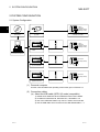
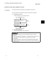
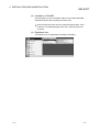
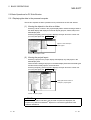
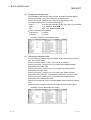
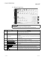
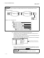
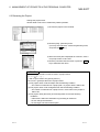
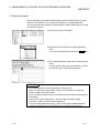
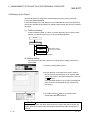
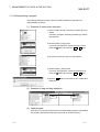
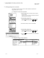
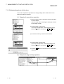
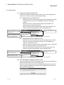
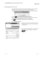
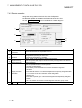
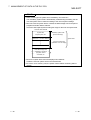
(1) Centralized management of project data
The project data (parameters, programs, comments, device data, etc.) of GX
Developer in a personal computer can be displayed as a list. (On Windows,
projects are displayed as folders.)
The projects of GX Configurator-QP and GX Configurator-CC are displayed as
icons.
Projects in the personal computer can be moved, copied, deleted and renamed,
for example, easily from GX Explorer as if you are operating Windows Explorer,
without the need to run the created application, to ensure centralized
management of various projects.
Drives and folders of
personal computer are
displayed.
Projects of GX Developer,
GX Configurator-CC and
GX Configurator-OP are
displayed as icons.
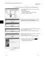
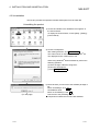
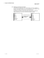
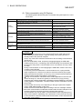
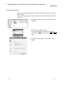
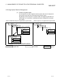
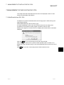
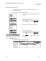
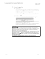
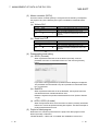
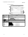
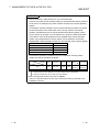
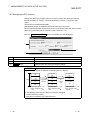
(2) Display of network configuration and data
The PLC type, station type and station number information of each station
(network configuration information) is gathered from MELSECNET/H,
MELSECNET/10 and/or CC-Link via the PLC connected with the personal
computer, and the configuration of each network is displayed on GX Explorer
from that information.
Selecting the PLC CPU in the displayed network configuration lists the data
(programs, parameters, etc.) in that PLC CPU.
Merely double-clicking the listed data starts GX Developer, allowing you to read
those data onto the personal computer and edit and save them without specifying
the network number and station number.
Configuration of
connected PLC,
MELSECNET/10(H) or
CC-Link is displayed.
1-1
Data (programs,
parameters, etc.) in PLC
CPU are displayed.
1-1
1 OVERVIEW
MELSOFT
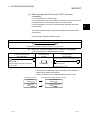
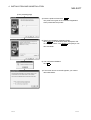
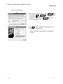
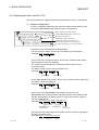
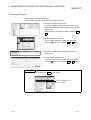
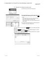
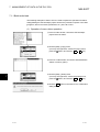
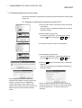
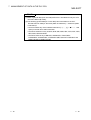
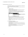
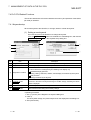
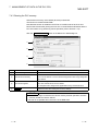
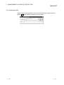
(3) Read/write from/to PLC CPU
Read from PLC and write to PLC can be done easily by performing drag and
drop operation to the displayed PLC CPU. When performing write/read to/from
multiple PLC CPUs continuously, for example, the operations of starting GX
Developer and opening/closing a project are not needed, ensuring efficient
operations.
Write to PLC
Read from PLC
(4) Starting the related application
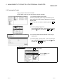
Double-clicking the project selected on GX Explorer starts the application used to
create that project, enabling you to edit and save the project.
Double-clicking a general file other than a project can also start the related
application.
Double-click!
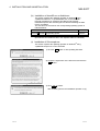
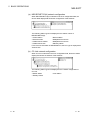
(5) Diagnostic functions
By choosing the required PLC CPU from a list display, you can perform PLC
diagnostics, network diagnostics, CC-Link diagnostics, Ethernet diagnostics or
system monitor.
You can display the error status, fault history or like of the PLC CPU and check
the network-based system status or like.
1-2
1-2
1
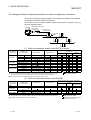
2 SYSTEM CONFIGURATION
MELSOFT
2 SYSTEM CONFIGURATION
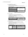
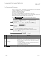
2.1 System Configuration
ACPU
QnACPU
QCPU(Q mode)
QCPU(A mode)
2
GX Explorer
(6) PLC CPU
Remote I/O module
(2) Cable
ACPU
QnACPU
QCPU(Q mode)
QCPU(A mode)
(3) MELSECNET/10(H)
board
(7) Network module
(1) Perasonal comperter
QnACPU
QCPU(Q mode)
(4) CC-Link board
(8) Master/Local module
QnACPU
QCPU(Q mode)
(5) Ethernet board
(9) Interface module
(1) Personal computer
Use the one that satisfies the operating environment given in Section 2.2.
(2) Connection cables
(a) About the USB cable (QCPU (Q mode) compatible)
®
1) Usable when Windows 98 and USB driver have been installed.
®
®
2) Unusable for Windows 95, Windows NT , Workstation 4.0.
3) Use of the USB cable allows only one PLC CPU to be connected.
4) Use the USB cable which conforms to the USB Standard Rev. 1.1.
2-1
2-1
2 SYSTEM CONFIGURATION
MELSOFT
(b) About the cable (QCPU (Q mode), QCPU (A mode)
compatible)
For communication in 115.2/57.6 kbps
Fast communication cannnot be made if the Personal computer used is not
compatible with the communication speed of 115.2/57.6 kbps.
If a communication error occurs, reduce the baud rate etting and restart
communication.
The following cable has been confirmed by Mitsubishi Electric that it will
work properly.
Using the cable of Mitsubishi Electric make.
RS-232 cable
QC30R2 (when Personal computer connector is D-sub, 9-pin)
(c) About the converter/cable (ACPU, QnACPU compatible)
1) Using the products of Mitsubishi Electric make
Personal computer Side
RS-232C/RS-422
PLC CPU Side
(RS-232C cable)
Converter
(RS-422 cable)
For ACPU, QnACPU, FX1/FX2CPU/FX2CCPU
F2-232CAB-1
FX-232AW(C)
(when Personal computer connector is
D-sub, 9-pin)
FX-422CAB (0.3m)
FX-422CAB-150 (1.5m)
• How to identify compatibility of the F2-232CAB and F2-232CAB-1
cables with the ACPU and QnACPU
Check the indication of the model label attached to the cable.
Incompatible products
2-2
Compatible products(with indication of F/FX/A)
F2-232CAB
Y990C
F2-232CAB(F/FX/A)
Y990C
F2-232CAB-1
Y990C
F2-232CAB-1(F/FX/A)
Y990C
2-2
2
2 SYSTEM CONFIGURATION
MELSOFT
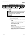
(3) MELSECNET/10(H) boards
The following are the compatible drivers.
Refer to the manual of the corresponding board for the board connection and
driver installation methods.
Type
Driver
A70BDE-J71QLP23
A70BDE-J71QLP23GE
SW3DNF-MNET10
A70BDE-J71QBR13
1
2
A70BDE-J71QLR23
Q80BD-J71BR11
SW0DNC-MNETH-B
Q80BD-J71LP21-25
1
®
1: Unusable with Windows Me.
®
2: Unusable with Windows 2000 Professional.
(4) CC-Link boards
The A80BD-J61BT11 allows setting of the master/local station.
The A80BD-J61BT13 is accessible only at the setting of a local station.
The following are the compatible drivers.
Refer to the manual of the corresponding board for the board connection and
driver installation methods.
Type
Driver
A80BE-J61BT11
SW4DNF-CCLINK-B
A80BE-J61BT13
®
: Unusable with Windows Me.
(5) Ethernet boards
Use the driver provided for an Ethernet board available on the market.
The following are the Ethernet boards/cards that have been confirmed by
Mitsubishi Electric to operate properly.
Refer to the manual of the corresponding board for the board connection and
driver installation methods.
Maker Name
3COM make
Ethernet
board/card
Ethernet board
2-3
Allied Telesis make
Type
Ethernet Link III LAN PC Card
Centre COM LA-PCM Ethernet PC Card LAN
Adapter
TDK make
10BASE-TLAN Card (model: LAN-CD021BX)
Allied Telesis make
RE2000 (ISA)
2-3
2 SYSTEM CONFIGURATION
MELSOFT
(6) Modules connectable for serial port/USB communication
(a) Modules connectable for serial port
PLC Series
Module Name
PLC CPU
Q series
MELSECNET/H
remote I/O
QnA series
PLC CPU
Module Type
Q00J, Q00, Q01, Q02(H), Q06H, Q12H, Q25H
QJ72LP25, QJ72BR15
Q2A, Q2AS(H), Q2AS1, Q2AS(H)S1, Q3A,
Q4A, Q4AR
A0J2H, A1S, A1FX, A1SJ, A1SH, A1SJH, A1N,
A2C, A2CJ, A2N(S1), A2S, A2SH, A171SH,
A series
PLC CPU
A172SH, A3N, A2A(S1), A3A, A2U(S1),
A2US(S1), A2AS(S1), A2AS-S30, A2AS-60,
A2USH-S1, A3U, A4U, A173UH(S1), A273UH,
Q02(H)-A, Q06H-A
(b) Modules connectable for USB communication
PLC Series
Q series
Module Name
PLC CPU
Module Type
Q02H, Q06H, Q12H, Q25H
(7) MELSECNET/10(H) network modules connectable for
MELSECNET/10(H) board
PLC Series
Q series
QnA series
A series
Module Type
QJ71LP21, QJ71LP21-25, QJ71BR11
AJ71QLP21, AJ71QBR11, A1SJ71QLP21, A1SJ71QBR11,
A1SJ71QLP21GE
AJ71LP21, AJ71BR11, A1SJ71LP21, A1SJ71BR11, A1SJ71LP21GE
(8) CC-Link master/local modules connectable for CC-Link board
PLC Series
Module Type
Q series
QJ61BT11
QnA series
AJ61QBT11, A1SJ61QBT11
: Function version B or later only
(9) Ethernet interface modules connectable for Ethernet board
PLC Series
Module Type
Q series
QJ71E71, QJ71E71-B2, QJ71E71-100
QnA series
AJ71QE71, AJ71QE71-B5, A1SJ71QE71-B2, A1SJ71QE71-B5
: Only function version B or later of QnACPU and Ethernet interface module
2-4
2-4
2 SYSTEM CONFIGURATION
MELSOFT
2.2 Operating Environment
The following is the operating environment of GX Explorer.
Item
Description
®
200MHz or more (recommended) Pentium personal
Computer
®
computer on which Windows operates
®
®
®
®
®
®
Microsoft Windows 95 operating system
Microsoft Windows 98 operating system
Operating System
Microsoft Windows Me operating system
®
®
Microsoft Windows NT Workstation 4.0 operating system
®
®
Microsoft Windows 2000 Professional operating system
Necessary memory
64MB or more recommended
Free hard
For installation
100MB or more
disk area
For operation
100MB or more
Disk drive
CD-ROM disk drive
Display resolution
800
Required software
GX Developer Version 7 or later (SW7D5C-GPPW or later)
600 dots or more
®
Do not use USB with Windows 95.
POINT
• Instruction for use of the online manual
Addition of memory ensures more comfortable use.
• Instruction for use of the PDF data
Use with addition of personal computer memory ensures comfortable operation.
2-5
2-5
3 FUNCTION LISTS
MELSOFT
3 FUNCTION LISTS
3.1 Function Lists
(1) Common
View
New
Options
Function
Display/arrangement of
windows
Creation of new system data
Description
Displays and arranges the personal computer side window and PLC
side window.
Creates (registers) new system data.
GX Developer setting
Makes setting at start of related application.
Backup setting
Sets the drive or system data to be backed up.
Sets the getting of the network configuration information at start of GX
Explorer, at switching to the online mode, or at changing the transfer
setup.
Displays Help.
Network check setting
Others
Help
Refer To
Section 5.2.1
Section 6.8
Section 7.1.2
Section 7.2
Section 6.9
Section 5.1.1
Chapter 9
(2) Management of projects in personal computer
Function
Tree display/list display
Switching between list
display and detail display
View
Display of properties
Rename
Delete
Cut
Copy
Description
Displays the objects (projects, folders, files).
Switches between list display and detail display of the objects
(projects, folders, files).
Changes the display in name order, type order, size order or date
order.
Updates information on the objects (projects, folders, files) in the
personal computer.
Displays the information on the object (project, folder, file).
Changes the names of the object (project, folder, file).
Deletes the object (project, folder, file).
Cuts the object (project, folder, file).
Copies the object (project, folder, file).
Paste
Pastes the object (project, folder, file).
Creation of new folder
Creation of new project
Start of application
Creates a new folder.
Creates a new project of GX Developer.
Starts an application to open the selected project.
Arrangement of icons
Refresh
Object
operation
Refer To
Section 5.3.1
Section 6.4
Section 6.3
Section 6.2
Section 6.5
Section 6.6
Section 6.5
Section 6.6
Section 6.1
Section 6.7
(3) Management of data inside PLC
Function
Tree display/list display
List display/detail display
View
Arrangement of icons
Refresh
Online
(When
personal
computer and
PLC are
connected)
Save/read
Others
3-1
Delete PLC data
Description
Displays the PLC CPU data/network configuration.
Displays the network configuration list/PLC CPU data details.
Changes between the ascending sequence and descending sequence
in network number, order or station order.
Updates the connected stations or whole network configuration
information.
Deletes the PLC CPU file.
Write to PLC
Writes the programs, parameters and/or like to the PLC CPU.
Read from PLC
Reads the programs, parameters and/or like from the PLC CPU.
Diagnostics
Displays the PLC CPU or network status.
Reads the programs, parameters or like and edits them on GX
Developer.
Run a related application
Save of network
configuration information
Read of network
configuration information
Transfer setup
Offline mode
Refer To
Section 5.4.2
Section 7.3
Section 7.1.1
to
Section 7.1.7
Chapter 8
Section 7.2
Saves the read network configuration information.
Reads the saved network configuration information.
Specifies the interfaces and types to be connected with the PLC CPU.
Displays the network configuration information already gotten when the
network is not connected with the PLC CPU.
Section 5.4.1
Section 5.4.3
Section 5.4.4
3-1
3
3 FUNCTION LISTS
MELSOFT
3.2 Menu Lists
(1) Drop-down menus
The drop-down menus are indicated on the PC side window or PLC side window
selection status basis.
(a) When PC side window is selected
Menu Name
Description
New System data
New
3
File
Creates new system data.
Folder
Creates a new folder.
GX Developer project
Creates a new project of GX Developer.
Delete
Edit
Rename
Changes the name of the selected object.
Section 6.3
Properties
Displays the properties of the selected object.
Exit GX Explorer
Exits GX Explorer.
Cut
Moves the selected object to the clipboard (temporary
storage memory in personal computer).
Section 6.5
Copy
Copies the selected object to the clipboard (temporary
storage memory in personal computer).
Section 6.6
Paste
Pastes the cut or copied object to the selected position.
Section 6.5,
Section 6.6
Select All
Selects all objects in the window.
Section 6.2,
Section 6.5,
Section 6.6
Move up
Displays the data one layer above the current one.
Section 5.3.1
Toolbar
Switches between displaying and hiding the toolbar.
Status bar
Switches between displaying and hiding the status bar.
List
Displays a list of the objects in the window.
Arrange Icons
3-2
Section 6.4
Section 5.1.2
Section 5.2.1
Displays details of the objects in the window.
by Name
Displays the objects in the window in name order.
by Type
Displays the objects in the window in type order.
by Size
Displays the objects in the window in size order.
by Date
Displays the objects in the window in date order.
Refresh
Help
Section 6.1
Section 6.2
View
Window
Refer To
Section 6.8
Deletes the selected object.
Details
Tools
Button
Section 5.3.1
Updates the personal computer side window.
Options
Opens the Options dialog box.
Open PLC side window
Displays the PLC side window.
Close
Closes the active window.
Close All
Closes all open windows.
Cascade
Displays the windows one over another partially.
Tile Vertically
Displays the windows side by side.
Tile Horizontally
Displays the windows top to bottom.
Key operation list
Displays the key operations.
Product information
Displays the product information.
Connect to MELFANSweb
Connects to MELFANSweb.
Section 5.1.1,
Section 6.9,
Section 7.1.2,
Section 7.2
Section 5.2.1
Chapter 9
3-2
3 FUNCTION LISTS
MELSOFT
(b) When PLC side window is selected
Menu Name
File
Edit
View
Online
Tools
Window
Help
Description
Read Network configuration
information
Reads the saved network configuration information.
Save Network configuration
information
Saves the acquired network configuration information.
Button
Refer To
Section 5.4.3
Offline mode
Switches between the online and offline modes.
Section 5.4.4
Exit GX Explorer
Exits GX Explorer.
Section 5.1.2
Copy
Performs read from the selected PLC CPU.
Paste
Performs write to the selected PLC CPU.
Move up
Displays the data one layer above the current one.
Toolbar
Switches between displaying and hiding the toolbar.
Status bar
Switches between displaying and hiding the status bar.
List
Displays a list of the objects in the window.
Details
Arrange
Icons
Section 7.1.1 to
Section 7.1.7
Section 5.4.2
Section 5.2.1
Displays details of the objects in the window.
by Name
Displays the objects in the window in name order.
by Station No.
Displays the objects in the window in station number order.
Section 5.4.2
Network configuration
information refresh
Updates the network configuration information.
Transfer setup
Specifies the interface and like for connection to the PLC
CPU.
Section 5.4.1
Options
Opens the Options dialog box.
Section 5.1.1,
Section 6.9,
Section 7.1.2,
Section 7.2
Open PC side window
Displays the personal computer side window.
Close
Closes the active window.
Close All
Closes all open windows.
Cascade
Displays the windows one over another partially.
Tile Vertically
Displays the windows side by side.
Tile Horizontally
Displays the windows top to bottom.
Key operation list
Displays the key operations.
Product information
Displays the product information.
Connect to MELFANSweb
Connects to MELFANSweb.
Section 5.2.1
Chapter 9
(c) When PC side and PLC side windows are not being displayed
Menu Name
File
View
Tools
Window
Help
3-3
Description
Exit GX Explorer.
Exits GX Explorer.
Toolbar
Switches between displaying and hiding the toolbar.
Status bar
Switches between displaying and hiding the status bar.
Options
Opens the Options dialog box.
Open PC side window
Displays the personal computer side window.
Open PLC side window
Displays the PLC side window.
Key operation list
Displays the key operations.
Product information
Displays the product information.
Connect to MELFANSweb
Connects to MELFANSweb.
Button
Refer To
Section 5.1.2
Section 5.2.1
Section 5.1.1,
Section 6.9,
Section 7.1.2,
Section 7.2
Section 5.2.1
Chapter 9
3-3
3 FUNCTION LISTS
MELSOFT
(2) Shortcut menus
The following are the shortcut (right-click) menu on a PC side window or PLC
side window selection basis.
(a) When PC side window is selected
Menu Name
Description
Run a related application
View
Arrange Icons
Starts the application with which the project or file has been created.
List
Displays a list of the objects in the window.
Details
Displays details of the objects in the window.
by Name
Displays the objects in the window in name order.
by Type
Displays the objects in the window in type order.
by Size
Displays the objects in the window in size order.
by Date
Refer To
Section 6.8
Section 5.3.1
Displays the objects in the window in date order.
Cut
Moves the selected object to the clipboard (temporary storage memory
in personal computer).
Section 6.5
Copy
Copies the selected object to the clipboard (temporary storage
memory in personal computer).
Section 6.6
Paste
Pastes the cut or copied object to the selected position.
Section 6.5,
Section 6.6
Delete
Deletes the selected object.
Section 6.2
Rename
Changes the name of the selected object.
Section 6.3
New
Folder
Creates a new folder.
GX Developer project
Creates a new project of GX Developer.
Properties
Displays the properties of the selected object.
Section 6.1
Section 6.4
(b) When PLC side window is selected
Menu Name
Run a related application
Network configuration information refresh
View
Arrange Icons
Description
Starts GX Developer.
Updates the network configuration information.
List
Displays a list of the objects in the window.
Details
Displays details of the objects in the window.
by Name
Displays the objects in the window in name order.
by Station No.
Performs read from the selected PLC CPU.
Paste
Performs write to the selected PLC CPU.
Diagnostics
Section 7.1.1 to
Section 7.1.7
Deletes the selected file from the PLC CPU.
Section 7.3
PLC diagnostics
Diagnoses the selected PLC CPU.
Section 8.1
Network diagnostics
Diagnoses the selected network.
Section 8.2
CC-Link diagnostics
Diagnoses the selected CC-Link system.
Section 8.3
System monitor
Monitors the configuration of the selected station.
Section 8.5
Ethernet diagnostics
Diagnoses selected Ethernet.
Section 8.4
Offline mode
Switches between the online and offline modes.
Read Network configuration information
Reads the saved network configuration information.
Save Network configuration information
Saves the acquired network configuration information.
3-4
Section 5.4.2
Displays the objects in the window in station number order.
Copy
Delete PLC data
Refer To
Section 7.2
Section 5.4.4
Section 5.4.3
3-4
4 INSTALLATION AND UNINSTALLATION
MELSOFT
4 INSTALLATION AND UNINSTALLATION
This chapter describes the installation and uninstallation of GX Explorer.
4.1 Installation
This section explains the installation procedure and operation of GX Explorer.
(1) Installation procedure
Install GX Developer in the following procedure.
New installation
Install the product.
Register the Name and Company.
Register the product ID.
Refer to
Section 4.1.
Boot the application.
Check whether the product has been
installed properly.
Refer to
Section 5.1.1.
4
Complete
(2) Installation operation
Check the following before starting installation.
POINT
• Before starting installation, close all other applications that are running on
®
Windows .
®
®
• When using Windows NT Workstation 4.0 or Windows 2000 Professional, log
on as a user who has the attributes of an administrator (for computer
management).
• If GX Developer Version 7 or later has not been installed, GX Explorer can be
installed but cannot be booted. When using GX Explorer, install GX Developer
Version 7 or later.
4-1
4-1
4 INSTALLATION AND UNINSTALLATION
MELSOFT
®
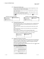
(a) Installing the product (The screen is that of Windows 95.)
®
1) Boot Windows Explorer and click the drive where the
disk is inserted.
Double-click "Setup.exe".
®
To display Windows Explorer, choose [Start] [Programs] - [Windows Explorer].
Double-click here.
2) If either of the left screens appears, perform operation in
accordance with the instructions given in (b).
After the operation is over, restart installation operation.
4
If the left screen appears, perform operation in accordance
with the instructions given in (c).
After the operation is over, restart installation operation.
If the left screen appears, perform operation in accordance
with the instructions given in (d).
After the operation is over, restart installation operation.
3) Type the name and company, and click Next> .
As the confirmation dialog box appears, follow the
message and perform operation.
(To next page)
4-2
4-2
4 INSTALLATION AND UNINSTALLATION
MELSOFT
(From preceding page)
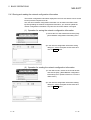
4) Enter the product ID and click Next> .
The product ID is given in the "Software Registration
Card" packed with the product.
5) Specify the installation destination folder.
Click Next> if the destination folder displayed is OK.
To change the folder, click Browse and specify a new
drive and folder.
6) This completes installation.
Click OK .
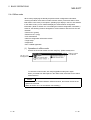
7) If the screen shown on the left appears, you need to
®
reboot Windows .
4-3
4-3
4 INSTALLATION AND UNINSTALLATION
MELSOFT
(b) Installation of dcom95.exe or Axdist.exe
This section explains the updating operation of Windows using
"Update\dcom95.exe" or "Update\Axdist.exe" on the CD-ROM.
Execute dcom95.exe or Axdist.exe provided for GX Explorer.
Install GX Explorer after executing the exe file and restarting the IBMPC/AT compatible.
The exe file to be executed on the corresponding operating system is
indicated below.
R
OS
Microsoft Windows 95 Operating System
Microsoft Windows 98 Operating System
Microsoft Windows NT Workstation Operating System Version 4.0
R
R
R
R
R
R
File name
dcom95.exe
Axdist.exe
Axdist.exe
(dcom95.exe and Axdist.exe are in the "Update" folder on CD-ROM.)
(c) Installation of 50comupd.exe
®
This section explains the updating operation of Windows using
"Update\50comupd.exe" on the CD-ROM.
1) Click the Yes button to start updating Windows.
2) Accept the agreement on the left screen and click the
Yes button.
3) Click Yes to restart.
After a restart, perform the installation operation in (a).
4-4
4-4
4 INSTALLATION AND UNINSTALLATION
MELSOFT
(d) Installation of EnvMEL
Execute Setup.exe in the "EnvMEL" folder on this product CD-ROM.
Install GX Explorer after executing the "Setup exe".
: After executing the above exe file, install the product again. If this
product is not installed properly at this time, reboot the personal
computer.
(e) Registered icon
The following icon is registered by installing GX Explorer.
4-5
4-5
4 INSTALLATION AND UNINSTALLATION
MELSOFT
4.2 Uninstallation
This section provides the operation to delete GX Explorer from the hard disk.
Uninstalling the product
1) Choose and double-click "Add/Remove Programs" in
the Control Panel.
To display the Control Panel, choose [Start] - [Setting] [Control Panel].
2) Choose "GX Explorer".
After making selection, click Add/Remove .
®
The screen shown on the left is that of Windows 95.
The displayed screen varies with the OS.
®
When using Windows 2000 Professional, perform the
following operation.
(a) Click "Change or Remove Programs".
(b) Choose "GX Explorer"
(c) Click Change/Remove .
(To next page)
4-6
3) Check whether you will romove the software package or
not.
When uninstalling it, click Yes .
Uninstallation starts.
When not uninstalling it, click No .
This returns to the preceding screen.
Components indicate the icons and files installed.
4-6
4 INSTALLATION AND UNINSTALLATION
MELSOFT
(From the preceding page)
4) If the left screen has appeared, click the No To All button.
If you click the Yes or Yes To All button, the shared file
of the Windows compatible MELSOFT software is
removed. Therefore, click the No To All button when
removing GX Explorer only.
R
5) Click OK when the message indicating that removing
operation is finished appears.
When the finished message appears, uninstallation is
complete.
4-7
4-7
5 BASIC OPERATIONS
MELSOFT
5 BASIC OPERATIONS
The following is the overview of GX Explorer operations.
Start GX Explorer.
Refer to Section 5.1.1.
Management of data
in PLC CPU
Management of projects
in personal compute
Specify Connection station
in Transfer setup.
Refer to
Section 5.4.1.
Display in PLC side window
Refer to
Section 5.4.2.
5
Display in PC side window
Refer to
Section 5.3.1.
Management of projects in
personal computer
Refer to
Chapter 6.
Management of projects
in PLC CPU
Exit from GX Explorer.
Refer to
Chapter 7.
Diagnostics of PLC CPU
and network
Refer to
Chapter 8.
Refer to Section 5.1.2.
: A connection station indicates the PLC CPU connected with the personal computer by a connection cable
(RS-232, USB), MELSECNET/10(H) board, CC-Link board or Ethernet board.
The PLC series, PC side I/F, PLC side I/F, etc. must be set in Transfer setup.
5-1
5-1
5 BASIC OPERATIONS
MELSOFT
5.1 Starting and Exiting
5.1.1 Starting
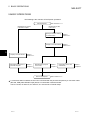
The following is a sequence of operations for starting GX Explorer.
When it is started for the first time or
the network configuration information
is not yet acquired
When the network configuration information
is already acquired
When the network check has
been set in Options
When the network check has
not been set in Options
5
When the network configuration
and connection station have not
been changed
Yes
When the network
configuration has been
changed or disabled for
communication
When the network configuration has
not been changed but the connection
station has been changed 1
(The station has been connected to
another PLC CPU in the network)
No
2
Yes
PLC side window is
displayed without
network
configuration. 3
PLC side window is
displayed with the
acquired network
configuration.
PLC side window is
displayed with the
new network
configuration.
PLC side window is
displayed with the
network
configuration already
acquired in the
offline mode (refer
to Section 5.4.4).
PLC side window is
displayed with the
new network
configuration.
No
PLC side window is
displayed with the
network
configuration already
acquired in the
offline mode (refer
to Section 5.4.4).
Cancel
PLC side window is
displayed with the
acquired network
configuration. 4
Note: The PC side window displays the drives, projects, folders and files in the personal computer.
1: Refer to Section 5.4.5 for changing the connection station.
2: If communications cannot be made due to Transfer setup PLC type mismatch, communication error, PLC CPU poweroff or like, click No or Cancel.
After starting GX Explorer, check the connection cables, PLC CPU power and Transfer setup (refer to Section 5.4.1).
3: After starting GX Explorer, make Transfer setup and get the network configuration information.
4: The displayed network configuration may not match the actual network configuration.
Update the network configuration information before starting management or diagnostics of the data in the PLC CPU.
(Refer to Section 5.4.2.)
5-2
5-2
5 BASIC OPERATIONS
MELSOFT
POINT
• GX Developer (SW7D5C-GPPW or later) must have been installed to start GX
Explorer.
• The processing at start of GX Explorer varies with the network check setting in
Options.
To make the network check setting, click the [Tools]-[Options] menu and make
setting on the Network check setting screen in the Options dialog box.
Connection station check : Checks whether the PLC types of the connection
stations and the presence/absence of networks
match the network configuration information.
After Target setup is finished, a connection station
check is made automatically. (Refer to Section 5.4.1
for Target setup.)
Total station number check: Checks whether the total number of stations actually
connected in the networks matches the total number
of stations in the network configuration information.
5.1.2 Exiting
There are the following methods to exit from GX Explorer.
• Click the [File] - [Exit GX Explorer] menu.
• Click on the left of the title bar and click the [Close] menu.
• Click
on the right of the title bar.
• Press the shortcut keys Alt + F4 .
5-3
5-3
5 BASIC OPERATIONS
MELSOFT
5.2 Screen Layout
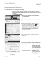
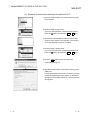
5.2.1 Basic screen layout
The following are the basic screen layout and dialog box of GX Explorer.
(1) Basic screen layout
This section explains the layout and common operations of the basic screen.
Drop-down menu
Title bar
Menu bar
Toolbar
Close
Minimize/
maximize/
return to
previous size
PC side
window
PLC side
window
Status bar
Project display field
Detail display field
PLC display field Device detail display field
Purpose
5-4
Operation
Switch between displaying and hiding the toolbar.
[View]-[Toolbar] menu
Switch between displaying and hiding the status bar.
[View]-[Status bar] menu
Open the PC side window.
[Window]-[Open PC side window] menu
Open the PLC side window.
[Window]-[Open PLC side window] menu
Close the active window.
[Window]-[Close] menu
Close all open windows.
[Window]-[All Close] menu
Display the windows one over another partially.
[Window]-[Cascade] menu
Display the windows side by side.
[Window]-[Tile Vertically] menu
Display the windows top to bottom.
[Window]-[Tile Horizontally] menu
5-4
5 BASIC OPERATIONS
MELSOFT
(a) Layout of PC side window
Displays the drives, folders, projects and files in the personal computer.
1) Project display field
Displays the drives, folders, projects and files in the personal computer
in a tree structure.
2) Detail display field
Selecting the drive or folder in the project display field displays the
objects in that drive or folder.
When the project of GX Developer is selected in the project display
field, its data are displayed in a tree structure.
(b) Layout of PLC side window
Displays the connected stations and network configuration.
1) PLC configuration field
Displays the connected stations and network configuration in a tree
structure.
2) Device detail information field
Selecting the network type in the PLC configuration field displays the
stations belonging to that network.
Selecting the station in the PLC configuration field displays the
memory (drive) structure and stored data of that station in a tree
structure.
(2) Basic operation for dialog box
1)
4)
1) Tabs
Click the setting item name to make
selection.
2)
2) Check box
To execute the item, click the check box
to check it.
3)
3) Text box
Enter a numeral/characters.
4) Command button
Click to execute "OK" or "Cancel".
5-5
5-5
5 BASIC OPERATIONS
MELSOFT
5.2.2 Icon lists
The following tables list icons displayed in the PC and PLC side windows of GX
Explorer.
(1) PC side window
Icon
Description
Removable media (e.g. FD, MO) drive
Local drive
CD-ROM drive
Network drive
System data
Backup folder
Project of GX Developer
Project of GX Configurator-QP
Master parameter setting file (extension ".CMP") or remote parameter setting file
(extension ".CRP") of GX Configurator-CC
Program (ladder) of GX Developer project
SFC program of GX Developer project
Global variables for label program of GX Developer project
Header for label program of GX Developer project
Body for label program of GX Developer project
Device comments (common comments) of GX Developer project
Program-based comments of GX Developer project
Parameters (PLC parameters) of GX Developer project
Network parameters or remote password of GX Developer project
Device memory of GX Developer project
Initial device values of GX Developer project
POINT
In the PC side window, files other than projects and their data are displayed by icons
®
associated by Windows Explorer.
5-6
5-6
5 BASIC OPERATIONS
MELSOFT
(2) PLC side window
Icon
Description
Online mode
Offline mode
QCPU (Q mode), QnACPU, ACPU, QCPU (A mode), remote I/O station
(MELSECNET/H)
MELSECNET/10(H) network, CC-Link system
Type unknown station
Network configuration information not yet acquired
Program memory/device memory of QCPU (Q mode)
Built-in RAM/device memory of QnACPU, ACPU or QCPU (A mode)
Memory card (RAM) of QCPU (Q mode)
IC memory card A (RAM) or IC memory card B (RAM) of QnACPU
Memory card (ROM) of QCPU (Q mode)
IC memory card A (ROM) or IC memory card B (ROM) of QnACPU
Standard RAM of QCPU (Q mode)
Standard ROM of QCPU (Q mode)
Program
Program (when password is set)
PLC parameters/network parameters/remote password of QCPU (Q mode)
PLC parameters/network parameters of QnACPU, ACPU or QCPU (A mode)
Intelligent parameters of QCPU (Q mode)
Common comments of QCPU (Q mode) or QnACPU
Extension comments of ACPU or QCPU (A mode)
Common comments of QCPU (Q mode) or QnACPU (when password is set)
Program-based comments of QCPU (Q mode) or QnACPU
Program-based comments of QCPU (Q mode) or QnACPU (when password is set)
Device memory
File registers
Device initial values of QCPU (Q mode) or QnACPU
Device initial values of QCPU (Q mode) or QnACPU (when password is set)
General data (PLC user data) of QCPU (Q mode)
5-7
5-7
5 BASIC OPERATIONS
MELSOFT
5.2.3 Shortcut key lists
The following tables list the shortcut keys of GX Explorer.
(1) When PC side window is active
Operation
Description
+ key
Opens the currently selected folder.
- key
Closes the currently selected folder.
key
key
Backspace
Ctrl + A
Opens the currently selected folder/selects the lower layer when the
folder is open.
Closes the currently selected folder/selects the upper layer when the
folder is closed.
Moves to the layer above the current one.
Selects all objects in the detail display field (invalid for the project detail
display).
Ctrl + X
Cut
Ctrl + C
Copy
Ctrl + V
Paste (Performs write to PLC on PLC side (after write to PLC, data is
not deleted by cut))
Ctrl + W
Creates new system data.
Ctrl + drag
Copies (performs write to PLC on PLC side).
Shift + drag
Moves (performs write to PLC on PLC side (after write to PLC, data is
not deleted)).
ALlt
F10
Alt + Enter
Alt + double-click
Makes the menu bar active.
Property display
Property display (only when the detail display field is in the list display
mode)
Alt + Space
Shortcut menu display of title bar
F1
Help display
F2
Rename
Ctrl + F4
Closes the window.
Alt + F4
Exits from the application.
F5
Updates the window data.
F6
Tab
5-8
Changes the active view to the project or detail display field.
Ctrl + F6
Change the active window to the PLC side window.
Shift + F10
Displays the shortcut menu of the selected item.
Delete
Deletes the selected object.
Shift + Delete
Deletes the selected object from the disk without moving it to the trash.
5-8
5 BASIC OPERATIONS
MELSOFT
(2) When PLC side window is active
Operation
Description
+ key
Opens the currently selected folder.
- key
Closes the currently selected folder.
key
key
Opens the currently selected folder/selects the lower layer when the
folder is open.
Closes the currently selected folder/selects the upper layer when the
folder is closed.
Backspace
Moves to the layer above the current one.
Ctrl + C
Copy
Ctrl + V
Paste (write to PLC)
Ctrl + drag
Shift + drag
Valid for the personal computer side only (read from PLC).
Alt
F10
Makes the menu bar active.
Alt + Space
Shortcut menu display of title bar
F1
Help display
Ctrl + F4
Closes the window.
Alt + F4
Exits from the application.
F5
Updates the data of the selected object.
F6
Changes the active view to the network configuration or device detail
Tab
display field.
Ctrl + F6
Change the active window to the personal computer side window.
Shift + F10
Displays the shortcut menu of the selected item.
POINT
Right-clicking the PC or PLC side window displays the shortcut (right-click) menu.
5-9
5-9
5 BASIC OPERATIONS
MELSOFT
5.3 Basic Operations for PC Side Window
5.3.1 Displaying the data in the personal computer
This section explains the basic operations to be performed in the PC side window.
(1) Viewing the objects in the drive or folder
Choosing a drive or folder in the project display field or double-clicking a folder in
the detail display field displays its internal objects (projects, folders, files) in the
detail display field.
Choosing the [Edit] - [Move up] menu displays the layer above the current one.
(You may also press the Backspace key.)
Objects in "GX Developer"
folder appear.
Choose "GX Developer" folder.
(2) Viewing the project layout
Choosing a project in the project display field displays only that project in the
detail display field.
Further double-clicking that project in the detail display field shows the data types
and file names of that project in a tree structure.
Choosing the [Edit] - [Move up] menu displays the layer above the current one.
(You may also press the Backspace key.)
Data types and file names of
"Sample1" project appear.
Choose "Sample1" project.
POINT
Note that when folders and files in the personal computer are displayed, GX
®
Explorer may differ from Windows Explorer in icons and/or upper/lower-case
character indications.
5 - 10
5 - 10
5 BASIC OPERATIONS
MELSOFT
(3) Changing the display type
The detail display field has two display modes: list display and detail display.
Choosing the [View] - [List] menu selects the list display mode.
Choosing the [View] - [Details] menu selects the detail display mode.
In the detail display mode, the following items appear.
• Project .................. PLC type (GX Developer project only), Size, Type, Modified
• Folder ................... Type, Modified, Attributes
• File ........................ Size, Type, Modified, Attributes
There are the following attributes.
R: Read-only
H: Hidden
S: System
A: Archive
<Example of screen in detail display mode>
(4) Changing the display order
You can change the display order of the detail display field between the name,
type, size and date orders.
However, the basic "folder - project - file" order is not changed.
Choosing the [View] - [Arrange Icons] - [by Name] menu displays folders/
projects/files in the name order.
Choosing the [View] - [Arrange Icons] - [by Type] menu displays folders/
projects/files in the type order.
Choosing the [View] - [Arrange Icons] - [by Size] menu displays folders/
projects/files in the size order. (The folders are displayed in the name order.)
Choosing the [View] - [Arrange Icons] - [by Date] menu displays folders/
projects/files in the updated date order.
Clicking the corresponding item in the detail display mode changes the display
order.
(Clicking it again changes between the ascending and descending orders.)
<Example of screen displayed in size order>
5 - 11
5 - 11
5 BASIC OPERATIONS
MELSOFT
(5) Displaying the latest information
If the objects being displayed in the PC side window are moved or updated, for
example, using Windows Explorer or any other application, such changes are not
reflected on the display of the personal computer side window.
To display the new status, choosing the [View] - [Refresh] menu updates the
display. (Displaying the other layer automatically updates the data.)
Updated to the latest
information with
GX Explorer
5 - 12
5 - 12
5 BASIC OPERATIONS
MELSOFT
5.4 Basic Operations for PLC Side Window
5.4.1 Displaying the PLC configuration information
If there is no network configuration information at an initial start or like, display the
connection stations and network configuration in the PLC side window in the following
procedure.
(1) Operation sequence
1) Choose the PLC side window and click the [Online] [Transfer setup] menu.
2) Choose the PLC series in the Select PLC series dialog
box.
3) On the Transfer setup screen, set the "PC side I/F",
"PLC side I/F" and others and click the OK button.
(Refer to (2) for the Target setup screen.)
Making Target setup automatically starts a connection
station check which confirms the PLC types of the
connection stations and the presence/absence of
networks. (Refer to POINT in Section 5.1.1 for the
connection station check.)
4) Click the [View] - [Network configuration information
refresh] menu.
5) In the dialog box designed to confirm the updating of the
network configuration information, choose "Get all
stations" or "Connection station only".
• "Get all stations" ................... Updates the network
presence/ absence and
the PLC types, memory
names and stored data of
the connection stations
and all stations of each
network.
• "Connection station only" ..... Updates the network
presence/ absence and
the PLC types of the
connection stations.
(To next page)
5 - 13
5 - 13
5 BASIC OPERATIONS
From preceding page
MELSOFT
6) The confirmation dialog box appears on completion of
network configuration information updating.
7) The connection stations and their network configurations
are displayed in the PLC side window.
POINT
• The network configuration information that may be displayed depends on the PLC
series of the connection station and the position in the network. (Refer to Section
5.4.6 for the PLC series and range that may be displayed in the network
configuration information.)
• When the PLC was connected via the Q series Ethernet module and a remote
password was set to that Ethernet module, enter the remote password on the
following screen.
• When the network configuration information is acquired, its data can be saved by
choosing the [File] - [Save Network configuration information] menu.
The saved network configuration information can be read by choosing the [File] [Read Network configuration information] menu. (In the offline mode only)
For management of multiple systems, reading the saved network configuration
information eliminates the need to update the network configuration information
when the connection station is changed. (Refer to Section 5.4.3.)
5 - 14
5 - 14
5 BASIC OPERATIONS
MELSOFT
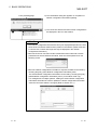
(2) Making the target setup
1)
2)
5)
3)
6)
7)
8)
9)
4)
10)
POINT
A yellow icon indicates that it has already been selected.
For details of Target setup, refer to the GX Developer Operating Manual.
No.
Item
1)
PC side I/F
2)
PLC side I/F
Description
Choose the personal computer side interface.
Double-clicking enables detail setting.
Choose the connected PLC side module.
Automatically selected according to the PC side I/F setting. (Need not be
3)
Other station
selected)
Double-clicking enables the setting of the communication time check period
and retry count.
4)
5)
6)
Multiple PLC setting
Connection channel list button
PLC direct coupled setting
button
You can specify any of No. 1 to No. 4 when the connection station is the
QCPU (Q mode) in a multiple PLC configuration.
Used to return the settings to the initial settings.
(The initial settings are "RS-232C", "PLC module" and "No specification".)
Used to display a list of selectable connection target paths and choose the
target path.
7)
Connection test button
Used to conduct a test for communication with the connection station.
8)
System image button
Used to display the selected connection target path by illustration.
9)
OK button
10)
Close button
5 - 15
Used to determine the target setup.
After determination, a connection station check is made automatically.
Used to cancel the settings and close the screen.
5 - 15
5 BASIC OPERATIONS
MELSOFT
(3) Paths connectable using GX Explorer
The following table indicates the paths connectable using GX Explorer on a PLC
series basis.
PLC Series
QCPU
(Q mode)
Description
Connected to the PLC CPU from the serial port by the RS-232 cable or
from the USB connector by the USB cable.
Connected to the MELSECNET/10(H) network module by the
MELSECNET/10(H) board.
Connected to the CC-Link master/local module by the CC-Link board.
Connected to the Ethernet interface module by the Ethernet board.
Connected to the remote I/O station of MELSECNET/H from the serial
port by the RS-232 cable.
Connected to the PLC CPU from the serial port by the RS-232 cable.
Connected to the MELSECNET/10 network module by the
MELSECNET/10(H) board.
QnACPU
Connected to the CC-Link master/local module by the CC-Link board.
Connected to the Ethernet interface module by the Ethernet board.
QCPU
(A mode)
ACPU
Connected to the PLC CPU from the serial port by the RS-232 cable.
Connected to the MELSECNET/10 network module by the
MELSECNET/10(H) board.
Connected to the PLC CPU from the serial port by the RS-232 cable.
Connected to the MELSECNET/10 network module by the
MELSECNET/10(H) board.
Name in Connection Path List
Serial port PLC module connection
MNET/10 (H) board communication Access
other station via MNET/10 (H) module
CC-Link board communication Access other
station via CC-Link module
Ethernet board communication Access
other station via Ethernet module
Serial port NET/10 (H) remote module
connection
Serial port PLC module connection
MNET/10 (H) board communication Access
other station via MNET/10 (H) module
CC-Link board communication Access other
station via CC-Link module
Ethernet board communication Access
other station via Ethernet module
Serial port PLC module connection
MNET/10 (H) board communication Access
other station via MNET/10 (H) module
Serial port PLC module connection
MNET/10 (H) board communication Access
other station via MNET/10 (H) module
POINT
• A communications error may occur if communications are made with the PLC
after setting the resume function, suspend setting, power-saving function or
standby mode of the personal computer.
Hence, any of the above functions should not be set for making communications
with the PLC.
• When the USB cable is used, frequently unplugging/plugging the USB cable,
resetting the PLC CPU, or switching power OFF/ON during communications with
the PLC CPU may cause a communications error, from which a recovery cannot
be made.
During communications, do not unplug/plug the USB cable, reset the PLC CPU,
or switch power OFF/ON.
If a recovery cannot be made from a communications error, unplug the USB
cable completely once, wait for more than five seconds, and then plug it again.
(After performing this operation, an error may occur at initial communication but
operation will be normal at and after the second time.)
During communications: Indicates that the related application in the PLC side
window is being run, write to PLC (paste) or read from PLC (copy) is being
performed, the network configuration information is being updated, the PLC data
is being deleted, or diagnostics, connection station check or total station check is
being made.
• Communication errors may occur depending on the type of personal computer
used or USB cable assembly In this case.
Please execute communication again according to the error message contents.
• When fast communication is made after the baud rate has been changed on the
personal computer's serial port (personal computer side interface),
communications may not be made or communications retries may take place to
delay communications, depending on the performance of the personal computer.
If communications cannot be made in fast communication, reduce the baud rate
and make communication.
5 - 16
5 - 16
5 BASIC OPERATIONS
MELSOFT
5.4.2 Displaying the data in the PLC CPU
This section describes the display operation to be performed in the PLC side window.
(1) Network configuration
The PLC configuration field shows the connection station and the station names
connected to MELSECNET/10(H) and CC-Link in a tree structure.
Station specified as connection station
Indicates MELSECNET/10(H) of network No. 1.
Shows the configuration of
MELSECNET/10(H) (network No. 1).
Indicates the first CC-Link module on the
normal station (station No. 2) of network No. 1.
Shows the configuration of CC-Link (first module).
The station names are displayed as indicated below.
• For the connection station, the PLC type and station type are displayed.
(Example) Q02H Connection station
PLC type
Station type
• For CC-Link on the connection station, the PLC type, module number, station
type and station number are displayed.
The module number indicates the master/local module number on the
connection station.
The station number is given to the local station only.
(Example) Q02H (board1) Local station No.1
PLC type
Station type
Module number
Station number
• For the MELSECNET/10(H) station, the PLC type, network number, station type
and station number are displayed.
(Example) Q02H (No.1) Control station No.1
PLC type
Station type
Network number
Station number
• For CC-Link on the MELSECNET/10(H) station, the PLC type, the
MELSECNET/10(H) network number and station number of the station loaded
with the master station, the station type of CC-Link and the station number of
CC-Link are displayed.
(Example) Q02H (No.1 No.2) (board1) Local station No.1
PLC type MELSECNET/10(H)
station number
MELSECNET/10(H)
network number
CC-Link
station type
Module number
CC-Link
station number
• For the QCPU (Q mode) multiple PLC system, the CPU number is displayed at
the end of the station name.
(Example) Q02H Connection station PLC No.2
PLC type
5 - 17
Station type
CPU No.
5 - 17
5 BASIC OPERATIONS
MELSOFT
(a) MELSECNET/10(H) network configuration
When MELSECNET/10(H) is selected in the PLC configuration field, the
device detail display field shows the configuration of that network.
The following station types are displayed in the station names of
MELSECNET/10(H).
• Control station
• Normal station
• Remote master
• Multiplexed remote sub
• Parallel remote master
• Multiplexed remote sub
• Parallel remote sub
• Stand by station
For the remote I/O station of MELSECNET/H, the PLC type is displayed as
"Remote I/O".
(b) CC-Link network configuration
When CC-Link is selected in the PLC configuration field, the device detail
display field shows the stations of that network.
The following station types are displayed in the network configuration of
CC-Link.
• Master station
• Local station
• Standby master
5 - 18
5 - 18
5 BASIC OPERATIONS
MELSOFT
POINT
In the following network configuration, the display example of the PLC configuration field is as shown
below.
• Network configuration
1) 3)
Q12H
CPU
4) 6)
Control
station
(No.1)
2)
MELSECNET/10(H)
Network No.1
Q06H
CPU
7) 9)
Normal
station
(No.2)
Control
station
(No.1)
5)
MELSECNET/10(H)
Network No.2
Q25H
CPU
Normal
station
(No.2)
Master
station
(board1)
8)
CC-Link
10)
A3U
CPU
Local
station
(No.1)
• Display in PLC configuration field
1)
2)
3)
4)
5)
6)
7)
8)
9)
10)
(2) Viewing the memories and data in the PLC CPU
Selecting a station in the PLC configuration field shows the memory names of
that station in the device detail display field.
Further double-clicking the memory name in the device detail display field shows
the stored data types and files in a tree structure.
However, the files in the hidden-attribute drive of the QnACPU are not displayed.
Further displays the data types and
file names + dates in a tree structure.
Select "Q02(H) connection station PLC No. 1".
When the device detail display field shows the network configuration or memory
configuration, choosing the [Edit] - [Move up] menu displays the layer above the
current one. (You may also press the Backspace key.)
POINT
• When SFC (MELSAP2) is stored in the ACPU, "MAIN + MELSAP2/
microcomputer" is displayed as Program.
5 - 19
5 - 19
5 BASIC OPERATIONS
MELSOFT
(3) Changing the display type
When the device detail display field shows the network configuration, you can
change between list display and detail display.
Choosing the [View] - [List] menu provides a list display (station names (PLC
types, station types)).
Choosing the [View] - [Details] menu provides a detail display (station names
(PLC types, station types), station numbers).
(The button can be used to provide a list display and the button a detail
display.)
<Example of screen for list display>
<Example of screen for detail display>
(4) Changing the display order
When MELSECNET/10(H) or CC-Link is selected in the PLC configuration field,
the device detail display field can be switched between the name order and
station number order.
Choosing the [View] - [Arrange Icons] - [by Name] menu shows data in name
order.
Choosing the [View] - [Arrange Icons] - [by Station No.] menu shows data in
station number order.
Click the "Name" or "Station No." item to change the display order.
(Clicking it again switches between ascending order and descending order.)
<Example of screen displaying MELSECNET/10(H) in name order>
(5) Displaying the latest information
If write to PLC is performed using GX Developer while data is being displayed in
the PLC side window, the data written is not reflected on the PLC side window.
To display new data, choose the [View] - [Network configuration information
refresh] menu to update the display data.
If you have modified the network configuration itself, choose "PLC" ( ) to update
the network configuration information.
5 - 20
5 - 20
5 BASIC OPERATIONS
MELSOFT
5.4.3 Saving and reading the network configuration information
The network configuration information displayed in the PLC side window can be saved
into the personal computer as a file.
Also, the saved network configuration information can be read in the offline mode.
By saving/reading the network configuration information, you need not update the
network configuration information every time the connection station is changed.
(1) Operation for saving the network configuration information
1) Choose the PLC side window and click the [File] [Save Network configuration information] menu.
2) In the network configuration information saving
dialog box, set the drive/path and file name and
click the Save button.
(2) Operation for reading the network configuration information
1) In the offline mode, choose the PLC side window
and click the [File] - [Read Network configuration
information] menu. (Refer to Section 5.4.4 for the
offline mode.)
2) In the network configuration information reading
dialog box, set the drive/path and file name and
click the Read button.
5 - 21
5 - 21
5 BASIC OPERATIONS
MELSOFT
5.4.4 Offline mode
When merely displaying the already acquired network configuration information,
choosing the offline mode does not make network checks (connection station check,
total station count check) in the options, speeding up a display in the PLC side window.
In the offline mode, you can read and display the saved network configuration
information. (Refer to Section 5.4.3 for reading the network configuration information.)
However, the following functions designed for communications with the PLC CPU are
unusable.
• Write to PLC (paste)
• Read from PLC (copy)
• PLC data deletion
• Network configuration information refresh
• Target setup
• Diagnostics
• Run a related application
(1) Operations in offline mode
Choose the PLC side window and click the [File] - [Offline mode] menu.
The "PLC" icon
is displayed red.
"[Offline]" appears
on the title bar.
To choose the online mode, click the [File]-[Offline mode] menu again.
When you exited from GX Explorer in the offline mode, also start it in the offline
mode next time.
POINT
When the mode is switched between offline and online, the network checks in the
options are executed.
(Refer to Section 5.1.1 for the network check setting.)
5 - 22
5 - 22
5 BASIC OPERATIONS
MELSOFT
5.4.5 Changing the connection station
The network configuration information of GX Explorer displays the network information
based on the connection station.
Hence, when you change the connection station, the already acquired network
configuration information becomes different from the actual network configuration
information, disabling communications with the specified station.
At the time of the connection station check, GX Explorer checks the match between
the network configuration information already acquired and the network configuration
information based on the information of the new connection station.
The following are the operations to be performed for match and mismatch.
(1) When match occurs
When you changed the connection station to the other station displayed in the
network configuration information, the network configuration information of the
new connection station matches the already acquired network configuration
information, and the station corresponding to the new connection station is
recognized from the already acquired network configuration information.
<When match occurs at connection station check>
When you did not change the network configuration, choose the Yes button.
The already acquired network configuration information is replaced by the
network configuration information based on the new connection station.
To replace the network configuration information takes shorter time than to
acquire the network configuration information again.
POINT
• When the connection station is changed from the QCPU (Q mode) to the
QnACPU, the QCPU (Q mode), QCPU (A mode) and ACPU are not displayed.
• When the connection station is changed from the QCPU (Q mode) to the QCPU
(A mode) or ACPU, the QCPU (Q mode) and QnACPU are not displayed.
• When the connection station is changed to any of the local stations in the same
configuration that consists of only CC-Link local stations, the new connection
station may not be recognized.
(Since the CC-Link local stations in the same configuration cannot be identified
between each other)
• When the connection station is changed to the ACPU other than the AnUCPU,
MELSECNET/10 is recognized as MELSECNET/II, resulting in network
configuration information mismatch.
5 - 23
5 - 23
5 BASIC OPERATIONS
MELSOFT
(2) When mismatch occurs
When you changed the network configuration or connected to the station of a
different network, the network configuration information of the new connection
station does not match the already acquired network configuration information.
<When mismatch occurs at connection station check>
Click Get all stations or Connection station only to get the new network
configuration information.
POINT
Reading the saved network configuration information eliminates the need to get the
network configuration information when the connection station is changed.
Refer to Section 5.4.3 for saving/reading the network configuration information.
5 - 24
5 - 24
5 BASIC OPERATIONS
MELSOFT
5.4.6 Ranges enabled for display and operation of network configuration information
This section provides the ranges enabled for the display and operation of the network
configuration information and their precautions.
The network up to the connection station and the relay networks 1, 2 given in (1) to (3)
are in the following ranges.
MELSECNET/10(H) board
CC-Link board
Ethernet board
Network up to
connection station
Connection
station
Serial/USB
Relay network 1
Relay network 2
(1) When the connection station is the QCPU (Q mode)
PC Side I/F in
Target Setup
Network Up to
Connection Station
Relay Network 1
MELSECNET/10 (H)
MELSECNET/10 (H)
CC-Link 2
CC-Link 2
Serial/USB
MELSECNET/
10(H) board
CC-Link board
Ethernet board
MELSECNET/10 (H)
1
MELSECNET/10 (H)
CC-Link 2
CC-Link 2
Ethernet
1
Ethernet
Ethernet
CC-Link
Display and Operation of Network Configuration
Information
ACPU
QCPU (Q mode)
QnACPU
QCPU (A mode)
Relay Network 2
1
1
CC-Link
2
MELSECNET/10 (H)
1
2
MELSECNET/10 (H)
MELSECNET/10 (H)
1
1
MELSECNET/10 (H)
CC-Link 2
1
CC-Link
2
1: Up to 7 relay stations and 8 networks are permitted when the routing parameters have been set.
Only the network of the connection station is permitted when the routing parameters have not been set.
Up to 1 gate and 2 networks are permitted when the connection station is a remote I/O station.
2: When the connection station and relayed station are the Q series master stations.
: Display/operation enabled
: Display/operation disabled
(2) When the connection station is the QnACPU
PC Side I/F in
Target Setup
Serial
MELSECNET/
10(H) board
CC-Link board
Ethernet board
Network Up to
Connection Station
MELSECNET/10 (H)
CC-Link
CC-Link
Ethernet
Relay Network 1
Relay Network 2
MELSECNET/10 (H)
1
MELSECNET/10 (H)
MELSECNET/10 (H)
1
1
Display and Operation of Network Configuration
Information
ACPU
QCPU (Q mode)
QnACPU
QCPU (A mode)
1
2
1: Up to 7 relay stations and 8 networks are permitted when the routing parameters have been set.
Only the network of the connection station is permitted when the routing parameters have not been set.
2: Display/operation enabled for the connection station only.
5 - 25
: Display/operation enabled
: Display/operation disabled
: Disable enabled, operation inhibited
(Refer to Section 5.4.6 (4))
5 - 25
5 BASIC OPERATIONS
MELSOFT
(3) When the connection station is the ACPU or QCPU (A mode)
PC Side I/F in
Target Setup
Network Up to
Connection Station
Relay Network 1
Serial
MELSECNET/
10(H) board
MELSECNET/10 (H)
MELSECNET/10 (H)
1
1
Relay Network 2
MELSECNET/10 (H)
1
MELSECNET/10 (H)
1
Display and Operation of Network Configuration
Information
ACPU
QCPU (Q mode)
QnACPU
QCPU (A mode)
1: Up to 7 relay stations and 8 networks are permitted when the routing parameters have been set.
Only the network of the connection station is permitted when the routing parameters have not been set.
: Display/operation enabled
: Display/operation disabled
(4) Instructions
The following are the instructions for the network configuration information using
GX Explorer.
IMPORTANT
When the connection station is the QnACPU, the QCPU (Q mode) in the network is
displayed as the Q4ACPU. Do not perform the following operations for the QCPU
(Q mode) that is displayed as the Q4ACPU. If any of the operations is performed,
we cannot guarantee proper operation of the QCPU (Q mode).
• Run a related application
• Write to PLC (paste)
• Read from PLC (copy)
• PLC data deletion
• Diagnostics
(a) When the network consists of different PLC series
Analyzing the network consisting of different PLC series takes much time to
get the network configuration information.
(b) When MELSECNET/10(H) exists in the network configuration
1) Display range when the connection station is the remote
I/O station
When the connection station is the remote I/O station of MELSECNET/
H, the routing parameters cannot be set and therefore the network that
can be displayed is only the network of the connection station.
2) Network configuration information getting time when the
routing parameter setting is illegal
When the routing parameter setting is illegal, correct network analysis
cannot be made and therefore it takes much time to get the network
configuration information.
3) Display provided when the same network numbers exist
When there are the same network numbers, only the network whose
information was acquired first can be displayed.
4) Routing parameters of the MELSECNET/10(H) board
If the routing parameters have not been set to the MELSECNET/10(H)
board, a routing parameter error occurs and the network configuration
information cannot be displayed.
5 - 26
5 - 26
5 BASIC OPERATIONS
MELSOFT
5) Station type-based display when the keyword is set on the
QnACPU
When the keyword has been set to the drive that stores the
parameters on the QnACPU, the station type is displayed as described
below.
Station Type
Remote master station, stand by station for Control
station, Multiplexed remote master station, Parallel
remote master station
Stand by station for Normal station, Multiplexed remote
submaster station, Pallel remote submaster station
Display of GX Explorer
Control station
Normal station
(c) When CC-Link exists in the network configuration
1) PLC series and station type of relay station
Only when the relay station is the QCPU (Q mode) and master station,
the network configuration is displayed. Any other CC-Link existing on a
local station cannot be displayed.
2) Station type that can be displayed
Only the master, local and standby master stations are displayed.
Remote I/O, remote device and intelligent device stations cannot be
displayed.
3) Remote I/O network mode and offline mode are not
displayed
The remote I/O network mode and offline mode are not displayed
since local stations do not exist in those modes.
4) Function version of the QnA series master/local module
When the local station is the QnACPU, only the function version B or
later can be displayed.
(d) PLC type display of the motion controller (SCPU)
The motion controllers (SCPUs) are displayed as the following ACPUs on
GX Explorer.
PLC Type
A171SH
A172SH
A173UH (S1), A273UH (S1)
Display of GX Explorer
A2SH
A3N
A3U
Write to PLC/read from PLC can also be performed for the projects of the
PLC type that is the motion controller (SCPU).
(e) When the ACPU is set in Target Setup and the QCPU (A
mode) is connected
If you set the "ACPU" as the PLC series of the connection station in Target
Setup and actually connected the QCPU (A mode), the connection station
is displayed as the A4U but it is operable as equivalent to the A4U.
5 - 27
5 - 27
5 BASIC OPERATIONS
MELSOFT
(f) Restrictions on/notes for communications
There are the following restrictions on/notes for communications to be
made with the PLC CPU displayed in the network configuration information.
Item
PLC
communication
Use of other packages
at the same port
Restriction/Note
During communication, e.g. PLC read/PC write, do not disconnect the cable for connection of
the personal computer and PLC CPU and connect it another PLC.
It is not possible to communicate with a PLC while using GPPA/APPQ at the same port. Either
use a different port or quit GPPA/GPPQ (close the DOS prompt too), before using the port.
When using the Windows version of, for example, SW[ ]NIW-GOT800P, simultaneous access
to the same port is not possible. Communication with one of the packages only is possible.
(g) When the routing parameters have been set for a Ethernet
module
When the routing parameters have been set for a Ethernet module, GX
Explorer regards it as MELSECNET/10(H) and therefore communicates
with all the stations at network analysis.
The device connected through Ethernet is not displayed because it is not to
be analyzed by GX Explorer.
Errors (Error code: C033H, C080H, C082H) occur and COM error is lit.
However, this will not effect on the system operation.
You can reset the above COM error by clicking the Clear history button
and the COM. ERR off button on the “Error history” tab screen for
Ethernet diagnosis.
5 - 28
5 - 28
6 MANAGEMENT OF PROJECTS IN THE PERSONAL COMPUTER
MELSOFT
6 MANAGEMENT OF PROJECTS IN THE PERSONAL COMPUTER
This chapter describes the management of projects in the PC side window.
6.1 Creating a New Project
Create a new project of GX Developer.
1) Choose the folder for creating a new GX Developer folder in
the project display field of the PC side window.
2) Click the [File] - [New] - [GX Developer project] menu.
(You may also right-click and click the [New] - [GX Developer
project] menu.)
3) In the new project dialog box, set the "PLC series", "PLC
type", "Program type", "Label setting", "Project name" and
"Title", and click the OK button. (Set the "Program type" and
"Label setting" for the QCPU (Q mode) or QnACPU only.)
• The number of characters of a project path + a project name
is within 150.
• The following characters cannot be used in a project name.
/, \, >, <, *, ?, ”, “, |, :, ;
(: and \ may be used to only specify a drive.)
• Do not use . (period) at the end of a project name.
• A title is within 32 characters long.
6
4) Clicking the Yes button creates a new GX Developer
project.
6-1
6-1
6 MANAGEMENT OF PROJECTS IN THE PERSONAL COMPUTER
MELSOFT
POINT
• By choosing the [File] - [New] - [Folder] menu, you can create a new folder.
• The following screen appears if a project of the same name exists in the folder.
• On GX Explorer, the folder registered as the system data can be displayed on the
top layer where the drive of the personal computer exists.
By gathering various projects in a specific folder and registering that folder as
system data, you can perform centralized and batch management of projects
more easily.
Refer to Section 6.8 for the system data.
<System data example>
Drive C
MELSEC
Position on Windows
R
Project
Demo1
Demo2
6
MELSOFT PROJECT
Demo1
Demo2
By registering a folder as system data "MELSOFT PROJECT",
it is displayed in the same column as the drive on GX Explorer.
6-2
6-2
6 MANAGEMENT OF PROJECTS IN THE PERSONAL COMPUTER
MELSOFT
6.2 Deleting the Project
Delete a project.
Another folder or file can be deleted by similar operation.
1) Choose the project to be deleted.
Choosing the [Edit] - [Select All] menu allows you to
batch-select the projects being displayed in the detail
display field.
(Batch selection can also be made by pressing Ctrl +
A .)
2) Click the [File] - [Delete] menu.
(You may also right-click, choose the [Delete] menu,
press the
button and click the Delete key.)
3) Click the Yes button in the deletion confirmation
dialog box.
: The deletion confirmation message may not be
displayed depending on the Trash property of
®
Windows .
POINT
Holding down the Shift key and performing deletion operation deletes the project
without moving it to Trash.
The icon that appears differs
from the one displayed when
the project is moved to Trash.
6-3
6-3
6 MANAGEMENT OF PROJECTS IN THE PERSONAL COMPUTER
MELSOFT
6.3 Renaming the Project
Change the project name.
Another folder or file can be renamed by similar operation.
1) Choose the project to be renamed.
2) Click the [File] - [Rename] menu.
(You may also right-click, choose the [Rename] menu,
and press the F2 key.)
3) Since the name part is displayed as a text box, enter a
new project name or file name.
4) Click the part other than the name or press the Enter
key to determine the name.
POINT
The following characters cannot be used in a project name.
/, \, >, <, , ?, ”, “, |, :, ;
(: and \ may be used to only specify a drive.)
Do not use . (period) at the end of a project name.
(1) The project name of GX Developer has the following condition.
• The number of characters of a project path + a project name is within 150.
(2) The project name of GX Configurator-QP has the following condition.
• The number of characters of a project name + a file name in the project is
within 150.
(3) The project name (file name) of GX Configurator-CC has the following
conditions.
• A file name is within 64 characters long including an extension.
• Do not change the extension.
• Do not begin a file name with a space.
6-4
6-4
6 MANAGEMENT OF PROJECTS IN THE PERSONAL COMPUTER
MELSOFT
6.4 Project Information
Display the information (properties) of a project or data (program, device comment or
like) in a project.
The information (properties) of another folder or file can also be displayed by similar
operation.
1) Choose the project or data whose information will be
displayed.
2) Click the [File] - [Properties] menu.
(You may also right-click, choose the [Properties]
menu, press the button, and click the Alt + Enter
keys.)
3) The information (properties) of the project or data
appears.
6-5
6-5
6 MANAGEMENT OF PROJECTS IN THE PERSONAL COMPUTER
MELSOFT
6.5 Moving the Project
Move a project to another drive/folder.
Another folder or file can also be moved by similar operation.
1) Choose the project to be moved.
Choosing the [Edit] - [Select All] menu allows you to
batch-select the projects being displayed in the detail
display field.
(Batch selection can also be made by pressing Ctrl +
A .)
2) Click the [Edit] - [Cut] menu.
(You may also right-click, choose the [Cut] menu,
press the
button, and click the Ctrl + X keys.)
3) Choose the destination drive/folder in the project
display field.
4) Click the [Edit] - [Paste] menu.
(You may also right-click, choose the [Paste] menu,
press the
button, and click the Ctrl + V keys.)
POINT
A project may also be moved by Shift + drag & drop.
Hold down Shift key and
drag and drop.
6-6
6-6
6 MANAGEMENT OF PROJECTS IN THE PERSONAL COMPUTER
MELSOFT
6.6 Copying the Project
Copy a project to another drive/folder.
Another folder or file can also be copied by similar operation.
1) Choose the project to be copied.
Choosing the [Edit] - [Select All] menu allows you to
batch-select the projects being displayed in the detail
display field.
(Batch selection can also be made by pressing Ctrl +
A .)
2) Click the [Edit]-[Copy] menu.
(You may also right-click, choose the [Copy] menu,
press the
button, and click the Ctrl + C keys.)
3) Choose the destination drive/folder in the project
display field.
4) Click the [Edit] - [Paste] menu. (You may also rightclick, choose the [Paste] menu, press the
button,
and click the Ctrl + V keys.)
POINT
A project may also be copied by Ctrl + drag & drop.
Hold down Ctrl key and
drag and drop.
6-7
6-7
6 MANAGEMENT OF PROJECTS IN THE PERSONAL COMPUTER
MELSOFT
6.7 Opening a Project
The GX Developer project/GX Configurator-QP project/GX Configurator-CC project
selected on GX Explorer can be opened and edited on the created application.
Another file can also be opened by similar operation if relation setting has been made
®
on Windows Explorer.
1) Choose the project to be edited.
2) Right-click and click the [Run a related application]
menu.
(You may also double-click and press the Enter key.)
3) The created application starts and the selected project
opens.
For open project editing and other operations, refer to
the manual of the corresponding application.
POINT
• The related application starts independently of GX Explorer.
When you performed project editing, saving or other operation to modify the
project, update it using GX Explorer.
If it is not updated, mismatch will occur between the actual data and the display of
GX Explorer.
• In the project of GX Configurator-CC, only the master parameter setting
(extension ".CMP") can start a related application.
Since the remote parameter setting (".CRP") cannot start a related application,
boot GX Configurator-CC from the start menu or like and open the project.
6-8
6-8
6 MANAGEMENT OF PROJECTS IN THE PERSONAL COMPUTER
MELSOFT
6.8 Using System Data for Management
(1) Outline of system data
On GX Explorer, the folder registered as the system data can be displayed on
the top layer where the drive of the personal computer exists.
By gathering various projects in a specific folder and registering that folder as
system data, you can perform centralized and batch management of projects
more easily.
<When C:\MELSEC\Project is registered as system data>
<When project is not registered as system data>
Drive C
Drive C
MELSEC
Position on Windows
MELSEC
R
Project
Project
Demo1
Demo1
Demo2
Demo2
MELSOFT PROJECT
Demo1
Demo2
By registering a folder as system data "MELSOFT PROJECT",
it is displayed in the same column as the drive on GX Explorer.
System data
6-9
Drive/folder
Project
6-9
6 MANAGEMENT OF PROJECTS IN THE PERSONAL COMPUTER
MELSOFT
(2) Operation for creating new system data
1) Click the [File] - [New System data] menu.
2) Set "System data name", "System folder" and "Title" in
the New System data dialog box, and click the OK
button.
• The system data name may be different from the
folder name registered as system data.
• As the system folder, set the folder registered as the
system data.
3) The system data name appears on the same layer as
the drives in the project display field.
The system folder can be set from the Browse button in the New System data
dialog box.
Clicking the Browse button displays the Folder selection dialog box. Choose
"Drive" and "Folder" and click the Open button.
The Folder selection dialog box closes and the folder selected is set in "System
folder" of the New System data dialog box.
6 - 10
6 - 10
6 MANAGEMENT OF PROJECTS IN THE PERSONAL COMPUTER
MELSOFT
POINT
(1) The system data name has the following conditions.
• The system data name is within 247 characters long.
• The following characters are unusable.
/, \, >, <, , ?, ", ", |, :, ;
• Any space following the folder name is automatically deleted.
• Any of the following system names is unusable.
COM1 to COM9, LPT1 to LPT9, AUX, CON, PRN, NUL, CLOCK$
(2) The folder that may be specified as the system folder has the following
conditions.
• The full path + system folder is within 247 characters long.
/, \, >, <, *, ?, ", ", |, :, ;
(: and \ may be set only to specify the drive.)
• Any space following the folder name is automatically deleted.
• You cannot specify the folder name that is followed by a period.
• You cannot specify a removable medium, (e.g. FD, MO) and CD-ROM drive.
• You cannot specify a network folder. (May be specified if it is registered to the
network drive.)
(3) The title is within 32 characters long.
(3) Changing the system data name
To change the system data name or title, choose the system data in the project
display field and click the [File] - [Rename] menu. (You may also press the F2
key.)
Enter the system data name or title and click the OK button.
(4) Deleting the system data
To delete (cancel) the system data, choose the system data to be deleted in the
project display field, and click the [File] - [Delete] menu. (You may also press the
Delete key.)
Clicking the OK button deletes (cancels) the system data.
However, the data within the folder specified as the system folder are not
deleted.
6 - 11
6 - 11
6 MANAGEMENT OF PROJECTS IN THE PERSONAL COMPUTER
MELSOFT
6.9 Backing Up the Project
The backup function is designed to automatically back up the project opened by
running the related application.
A removable medium (e.g. FD, MO) drive and a CD-ROM drive cannot be backed up.
This section explains the operations for making backup setting and returning a backed
up project.
(1) Outline of backup
Create a "Backup" folder on a drive or system data basis, and copy the project
that has not yet been opened by running the related application.
Drive C
MELSOFT PROJECT
Backup
Demo1
Data before editing
(opening) are copied.
Demo2
Running the related application
(2) Backup setting
This section describes the operation for making backup setting to the drive or
system data.
1) Click the [Tools]-[Options] menu.
2) Check "Backup" on the right of the drive or system
data name to be set for backup on the "System data
setting" tab screen in the Options dialog box, and click
the OK button.
(The removable medium (e.g. FD, MO), CD-ROM and
other drives are not displayed as they cannot be set
for backup.)
3) The folder named " Backup" is created for the
drive/system data set for backup.
POINT
If a project is saved in the folder within the drive or system data set for backup, the
folder of the same name is also created within the "Backup" folder at execution of
backup.
6 - 12
6 - 12
6 MANAGEMENT OF PROJECTS IN THE PERSONAL COMPUTER
MELSOFT
(3) Returning the backed up project
This section explains the operation for returning the modified project to the
backed up project.
1) Choose the project within the "Backup" folder that you
want to return.
2) Click the [Edit] - [Copy] menu.
(You may also right-click, click the [Copy] menu, click
the
button, and press the Ctrl + C keys.)
3) Choose the folder where the backup source project is
saved.
4) Click the [Edit] - [Paste] menu.
(You may also right-click, click the [Paste] menu, click
the
button, and press the Ctrl + V keys.)
5) As the folder overwrite confirmation dialog box
appears, click the Yes to All button.
6 - 13
6 - 13
7 MANAGEMENT OF DATA IN THE PLC CPU
MELSOFT
7 MANAGEMENT OF DATA IN THE PLC CPU
This chapter describes write/read to/from the PLC CPU displayed in the PLC side
window and data editing and deletion.
7.1 Write/Read to/from PLC CPU
GX Explorer can perform write/read to/from PLC using project or data cut/copy and
paste (drag and drop).
Write-enabled data vary with the memory type.
For write-enabled data, refer to the user's manual of the PLC CPU being used.
GX Explorer cannot perform online program correction to the PLC CPU.
Making online program correction to the PLC displays the remote STOP confirmation
dialog box.
Click the Yes button to execute write to PLC after remote STOP.
After completion of write to PLC, perform remote operation (refer to Section 7.4.2
(QCPU (Q mode), QnACPU only)) or move the RUN/STOP switch of the PLC CPU to
RUN.
Click No when you are not executing remote STOP and write to PLC.
7
7-1
7-1
7 MANAGEMENT OF DATA IN THE PLC CPU
MELSOFT
7.1.1 Batch-write/read
The following examples of write to PLC are used to explain the operations for batchwriting/reading the GX Developer project saved in the personal computer or the data
(programs, device comments, parameters, etc.) in the PLC CPU.
(1) Operation of menu-driven operation
1) In the PC side window, choose the GX Developer
project file to be written.
2) Click the [Edit] - [Copy] menu.
(You may also right-click, choose the [Copy] menu,
press the
button, and click the Ctrl + C keys.)
3) In the PLC side window, choose the write destination
station or memory (drive).
4) Click the [Edit] - [Paste] menu.
(You may also right-click, choose the [Paste] menu,
press the
button, and click the Ctrl + V keys.)
7
5) Click the Yes button in the write to PLC confirmation
dialog box.
7-2
7-2
7 MANAGEMENT OF DATA IN THE PLC CPU
MELSOFT
(2) Example of drag and drop operation
Drop
Drag
(3) Precautions for data types
Precautions are required for the data types included in write/read to/from PLC.
For details, refer to the following reference sections.
Program.........................: Refer to Section 7.1.2.
Device comment ...........: Refer to Section 7.1.3.
Parameter......................: Refer to Section 7.1.4.
Device memory .............: Refer to Section 7.1.5.
Device initial value ........: Refer to Section 7.1.6.
POINT
• When write/read is performed from the personal computer side window to the
PLC side window, [Cut] will not delete the project in the personal computer side
window.
• After write to PLC, you must perform such operation as reset to make the
parameters valid. Refer to the user's manual of the PLC CPU being used.
• If you do not choose a paste (read from PLC) destination project but select a
folder and paste (drop) the source project, it is read as a new project.
Its project name is "GX Developer project".
If the project of the same name exists in the folder, the project name will be "GX
Developer project " ( indicates a number in numerical order, starting from 1).
• For the remote I/O of MELSECNET/H, write/read to/from PLC is enabled for only
parameters.
• For the QCPU (Q mode) or QnACPU, performing write of a project including
device memory to PLC, with the PLC CPU or Program memory/Device memory
(PLC RAM/Device memory for the QnACPU) specified, does not write File
register data. Specify the memory to which file register data can be written.
7-3
7-3
7 MANAGEMENT OF DATA IN THE PLC CPU
MELSOFT
7.1.2 Writing/reading a program
The following examples of write to PLC are used to explain the operations for
writing/reading a program.
(1) Example of menu-driven operation
1) In the PC side window, choose the program file to be
written.
(Choosing "Program" indicating the data type selects
all programs.)
2) Click the [Edit] - [Copy] menu.
(You may also right-click, choose the [Copy] menu,
press the
button, and click the Ctrl + C keys.)
3) Choose the memory in the PLC side window.
4) Click the [Edit] - [Paste] menu.
(You may also right-click, choose the [Paste] menu,
press the
button, and click the Ctrl + V keys.)
5) Click the Yes button in the write to PLC confirmation
dialog box.
(2) Example of drag and drop operation
Drag
Drop
(3) Label program
Write to PLC cannot be performed if an uncompiled label program is included in
the program specified from the QCPU (Q mode) or QnACPU project.
7-4
7-4
7 MANAGEMENT OF DATA IN THE PLC CPU
MELSOFT
POINT
• If you do not choose a paste (read from PLC) destination project but select a
folder and paste (drop) the source project, a new project is created and only the
specified program is read. (The parameters are set to the initial values).
Its project name is "GX Developer project".
If the project of the same name exists in the folder, the project name will be "GX
Developer project " ( indicates a number in numerical order, starting from 1).
REMARK
The step reserved for online program correction can be changed on the "GX
Developer setting" tab screen in the Options dialog box.
(Choose the [Tools] - [Options] menu to open the Options dialog box.)
7-5
7-5
7 MANAGEMENT OF DATA IN THE PLC CPU
MELSOFT
7.1.3 Writing/reading parameters
The following examples of write to PLC are used to explain the operations for
writing/reading parameters.
(1) Example of menu-driven operation
1) In the PC side window, choose the parameter file to
be written.
2) Click the [Edit] - [Copy] menu.
(You may also right-click, choose the [Copy] menu,
press the
button, and click the Ctrl + C keys.)
3) Choose the memory in the PLC side window.
4) Click the [Edit] - [Paste] menu.
(You may also right-click, choose the [Paste] menu,
button, and click the Ctrl + V keys.)
press the
5) Click the Yes button in the write to PLC confirmation
dialog box.
(2) Example of drag and drop operation
Drop
Drag
7-6
7-6
7 MANAGEMENT OF DATA IN THE PLC CPU
MELSOFT
(3) Batch-writing/reading parameters
Since the parameter type (e.g. PLC parameter, network parameter) is not
differentiated in the PLC CPU, the parameter type cannot be specified to perform
write/read to/from PLC.
If you specify the parameter type in the PC side window, the parameters of all
types are batch-written.
POINT
• If you do not choose a paste (read from PLC) destination project but select a
folder and paste (drop) the source project, a new project is created and only the
parameters are read.
Its project name is "GX Developer project".
If the project of the same name exists in the folder, the project name will be "GX
Developer project " ( indicates a number in numerical order, starting from 1).
• After write to PLC, reset the PLC CPU or MELSECNET/H remote I/O.
Reset must be performed to make the written parameters valid.
For reset operation, refer to the user's manual of the PLC CPU being used.
7-7
7-7
7 MANAGEMENT OF DATA IN THE PLC CPU
MELSOFT
7.1.4 Writing/reading device comments
The following examples of write to PLC are used to explain the operations for
writing/reading device comments.
(1) Example of menu-driven operation
1) In the PC side window, choose the device comment
file to be written.
(Choosing "Device comment" indicating the data type
selects all device comments.)
2) Click the [Edit] - [Copy] menu.
(You may also right-click, choose the [Copy] menu,
press the
button, and click the Ctrl + C keys.)
3) Choose the memory in the PLC side window.
4) Click the [Edit] - [Paste] menu.
(You may also right-click, choose the [Paste] menu,
press the
button, and click the Ctrl + V keys.)
5) Click the Yes button in the write to PLC confirmation
dialog box.
(2) Example of drag and drop operation
Drag
7-8
Drop
7-8
7 MANAGEMENT OF DATA IN THE PLC CPU
MELSOFT
(3) Comment range setting
(a) Write to PLC
Write to PLC is performed only in the range of comment range setting.
If comment range setting has not been made for the ACPU or QCPU (A
mode), device comments cannot be written to the PLC.
Using GX Developer, make comment range setting.
If comment range setting has not been made for the QCPU (Q mode) or
QnACPU, the specified device comment file is written to the PLC.
(b) Read from PLC
For read of device comments to PLC, the following screen appears.
The comment range setting made on the PLC CPU side and the device
comments in that range are read to the PLC.
If comment range setting has not been made for the QCPU (Q mode) or
QnACPU, the specified device comment file is read to the PLC.
POINT
• If you do not choose a paste (read from PLC) destination project but select a
folder and paste (drop) the source project, a new project is created and only the
specified comments are read. (The parameters are set to the initial values.)
Its project name is "GX Developer project".
If the project of the same name exists in the folder, the project name will be "GX
Developer project " ( indicates a number in numerical order, starting from 1).
• When write to PLC is performed, an error will not occur if any write-disabled device
comment is included.
However, the write-disabled device comment is not written to the PLC.
7-9
7-9
7 MANAGEMENT OF DATA IN THE PLC CPU
MELSOFT
7.1.5 Writing/reading device memory data
This section describes the operations for performing write/read of device memory data
to/from PLC.
(1) Example of menu-driven operation for write to PLC
1) In the PC side window, choose the device memory file
to be written.
("Device memory" indicating the data type can also be
the target of write.)
2) Click the [Edit] - [Copy] menu.
(You may also right-click, choose the [Copy] menu,
press the
button, and click the Ctrl + C keys.)
3) Choose the memory in the PLC side window.
4) Click the [Edit] - [Paste] menu.
(You may also right-click, choose the [Paste] menu,
button, and click the Ctrl + V keys.)
press the
5) Click the Yes button in the write to PLC confirmation
dialog box.
Either of the following screens appears depending on
the target of write.
• When you performed write to other than
Program memory/Device memory (QCPU (Q
mode)) or to other than PLC RAM/Device
memory (QnACPU), set the number of file
register points. (When there are more than one
device memory file, their ranges are all the
same.)
7 - 10
• When you performed write to the ACPU or QCPU (A
mode), set write to device memory, write to file register
and its type (block No. 1 to 256 for Extension file
registers).
7 - 10
7 MANAGEMENT OF DATA IN THE PLC CPU
MELSOFT
(2) Example of menu-driven operation for read from PLC
1) In the PLC side window, choose the device memory
file to be read.
2) Click the [Edit] - [Copy] menu.
(You may also right-click, choose the [Copy] menu,
press the
button, and click the Ctrl + C keys.)
3) Choose the read destination project in the PC side
window. (If the project is not selected, a new project
name "GX Developer project" is created.
4) Click the [Edit] - [Paste] menu.
(You may also right-click, choose the [Paste] menu,
button, and click the Ctrl + V keys.)
press the
5) Click the Yes button in the read from PLC
confirmation dialog box.
6) Set "Device data name" in the Device memory read
dialog box.
For the file registers of the ACPU or QCPU (A mode),
set the file register type ("File register" or "Extension
file register") and further "Block No." for the extension
file registers.
7 - 11
7 - 11
7 MANAGEMENT OF DATA IN THE PLC CPU
MELSOFT
(3) Example of drag and drop operation
Device memory
Drop
MAIN
Drag
POINT
• If there are more than one device memory file in a project, the target of write
cannot be identified, and therefore write to PLC with the project or data type
specified cannot be performed to the Program memory/Device memory of the
QCPU (Q mode) or to the PLC RAM/Device memory of the QnACPU, ACPU or
QCPU (A mode).
Specify and read the file.
• If you do not choose a paste (read from PLC) destination project but select a
folder and paste (drop) the source project, a new project is created and only the
data of the specified device memory (file registers) are read. (The parameters are
set to the initial values.)
Its project name is "GX Developer project".
If the project of the same name exists in the folder, the project name will be "GX
Developer project " ( indicates a number in numerical order, starting from 1).
7 - 12
7 - 12
7 MANAGEMENT OF DATA IN THE PLC CPU
MELSOFT
7.1.6 Writing/reading device initial values
This section explains the operations for writing/reading device initial values to the
QCPU (Q mode) or QnACPU.
(1) Example of menu-driven operation
1) In the PC side window, choose the device initial value
file to be written.
("Device initial value" indicating the data type can also
be the target of write.)
2) Click the [Edit] - [Copy] menu.
(You may also right-click, choose the [Copy] menu,
press the
button, and click the Ctrl + C keys.)
3) Choose the memory in the PLC side window.
4) Click the [Edit] - [Paste] menu.
(You may also right-click, choose the [Paste] menu,
press the
button, and click the Ctrl + V keys.)
5) Click the Yes button in the write to PLC confirmation
dialog box.
(2) Example of drag and drop operation
Drop
Drag
7 - 13
7 - 13
7 MANAGEMENT OF DATA IN THE PLC CPU
MELSOFT
POINT
• If there are more than one device initial value file in the same memory of the PLC
CPU, the target of read cannot be identified, and therefore read from PLC with
the memory or data type specified cannot be performed.
Specify and read the file.
• If you do not choose a paste (read from PLC) destination project but select a
folder and paste (drop) the source project, a new project is created and only the
specified device initial value file is read. (The parameters are set to the initial
values.)
Its project name is "GX Developer project".
If the project of the same name exists in the folder, the project name will be "GX
Developer project " ( indicates a number in numerical order, starting from 1).
7 - 14
7 - 14
7 MANAGEMENT OF DATA IN THE PLC CPU
MELSOFT
7.1.7 Writing/reading general data
The following examples of write to PLC are used to explain the operations for
writing/reading general data (PLC user data) to the QCPU (Q mode).
(1) Example of menu-driven operation
1) In the PC side window, choose the general data file to
be written.
2) Click the [Edit] - [Copy] menu.
(You may also right-click, choose the [Copy] menu,
press the
button, and click the Ctrl + C keys.)
3) Choose the memory card (ROM) in the PLC side
window.
4) Click the [Edit] - [Paste] menu.
(You may also right-click, choose the [Paste] menu,
press the
button, and click the Ctrl + V keys.)
5) Click the Yes button in the write to PLC confirmation
dialog box.
(2) Example of drag and drop operation
Drag
7 - 15
Drop
7 - 15
7 MANAGEMENT OF DATA IN THE PLC CPU
MELSOFT
POINT
(1) Write of general data (PLC user data) to/from PLC is enabled for only the ATA
card of the QCPU (Q mode).
(2) The following general data (PLC user data) cannot be written to the PLC.
File that does not satisfy a "file name (within 8 characters) "." extension (within
3 characters)"
• File that includes any of the inhibited characters (" = | : ; , \ [ ] + ? < > . / and
space) in the file name and/or extension.
• File whose extension is any of QPG, QCD, QDI, QDR, QDL, QTD, QTX, QTR,
QFD, QAD, QTM and WTM
• File whose name is any of QN.QSY, WORK.QSY, TRACE.QSY,
PARAM.QPA, IPARAM.QPA, AUTOEXEC.QBT, Q00.DAT to Q99.DAT and
MONITOR.Q00 to MONITOR.Q0F
7 - 16
7 - 16
7 MANAGEMENT OF DATA IN THE PLC CPU
MELSOFT
7.1.8 Instructions
(1) Target of write/read to/from PLC
This section explains the target memory of write to PLC and the target data of
read from PLC using cut/copy and paste (drag and drop).
(a) Target memory of write to PLC
• When the PLC CPU is specified as the paste (drop) destination, Program
memory/Device memory or PLC RAM/Device memory is the target
memory.
• When the memory is specified as the paste (drop) destination, the
specified memory is the target memory.
• When the data type/file is specified as the paste (drop) destination, the
memory storing the specified data or file is the target memory.
When paste destination is memory,
write to PLC is performed to that
memory.
When paste destination is PLC CPU,
write to PLC is performed to Program
memory/Device memory or PLC RAM
/Device memory.
When paste destination is data or file,
write to PLC is performed to memory
which stores that data or file.
: Write to PLC cannot be performed if cut/copy (drag) source is in other than PC side window.
(b) Target data and file of read from PLC
• When the PLC CPU is specified as the cut/copy (drag) source, all data
and files in Program memory/Device memory or PLC RAM/Device
memory are the target of read.
• When the memory is specified as the cut/copy (drag) source, all data and
files in the specified memory are the target of read.
• When the data type/file is specified as the cut/copy (drag) source, the
memory storing the specified data or file is the target of read.
When cut/copy source is memory,
all data in that memory are are
read to PLC.
When cut/copy source is PLC CPU,
all data and files in Program memory
/Device memory or PLC RAM/Device
memory are read to PLC.
When cut/copy source is data or file,
that data or file is read to PLC.
: Write to PLC cannot be performed if paste (drop) destination is in other than PC side window.
(2) PLC series/types of project and PLC CPU
If the PLC series of the cut/copy source differs from that of the paste destination,
paste (write/read to/from PLC) cannot be performed.
If the PLC series of the cut/copy source and paste destination are the same but
their PLC types are different, the following screen appears before execution of
paste (write/read to/from PLC).
Change the PLC type of the project using GX Developer.
7 - 17
7 - 17
7 MANAGEMENT OF DATA IN THE PLC CPU
MELSOFT
(3) Motion controller (SCPU)
Since the motion controller (SCPU) is recognized as the ACPU by GX Explorer,
the project of any of the following PLC types is enabled for write/read to/from
PLC.
(a) Write to PLC
Write Source PLC Type (Project)
A171SH , A2SH
A172SH , A3N
A173UH (S1)
A3U
, A273UH (S1)
,
Write Destination CPU
A2SH, A171SH (displayed as A2SH on GX Explorer)
A3N, A172SH (displayed as A3N on GX Explorer)
A3U, A173UH(S1) (displayed as A3U on GX
Explorer), A273UH(S1) (displayed as A3U on GX
Explorer)
: Write to PLC is performed as the data of the motion controller (SCPU).
(b) Read from PLC
Read Destination PLC Type (Project)
A171SH , A2SH
A172SH , A3N
A173UH (S1)
A3U
, A273UH (S1)
,
Read Source CPU
A2SH, A171SH (displayed as A2SH on GX Explorer)
A3N, A172SH (displayed as A3N on GX Explorer)
A3U, A173UH(S1) (displayed as A3U on GX
Explorer), A273UH(S1) (displayed as A3U on GX
Explorer)
: Read from PLC is performed as the data of the motion controller (SCPU).
(4) Password/keyword setting
(a) QCPU (Q mode)
When a password has been set to the QCPU (Q mode), enter the
password at the time of write/read to/from PLC and click the [Execute]
button.
If you enter a wrong password, the password check dialog box reappears.
The password must be entered every time operation for write/read to/from
PLC is performed.
(b) QnACPU
When a password has been set to the QnACPU, the keyword cannot be
canceled at the time of write/read to/from PLC.
Delete the keyword and perform write/read to/from PLC. (Refer to Section
7.4 (2).)
(c) ACPU, QCPU (A mode)
When a keyword has been set to the ACPU or QCPU (A mode), write/read
to/from PLC cannot be performed using GX Explorer. Use GX Developer to
perform write/read to/from PLC.
(5) Project of label program
Read from PLC cannot be performed to the project of a label program of the
QCPU (Q mode) or QnACPU.
"Global variables", "Label" and "Local label" are disabled for write to PLC.
7 - 18
7 - 18
7 MANAGEMENT OF DATA IN THE PLC CPU
MELSOFT
7.2 Opening the Data in the PLC CPU
The data (programs, parameters, etc. other than general data (PLC user data)) stored
in the PLC CPU are read and edited on GX Developer.
The data of GX Configurator-QP and GX Configurator-CC cannot be opened from GX
Explorer.
(1) Operation example
Double-click the PLC CPU, memory or data you want to edit, or right-click and
click the [Run a related application] menu.
GX Developer starts and the data stored in the specified memory are read.
(Specifying the PLC CPU reads data from the program memory/device memory
for the QCPU (Q mode) or from the built-in RAM/device memory for the
QnACPU.)
Double-click, or right-click and
click [Run a related application]
menu.
When the device comments are stored in the PLC CPU, a screen appears to
warn that only the data of the comment range setting will be read. (Refer to
Section 7.1.4.)
When the device memory data are stored in the PLC CPU, the device memory
read dialog box appears. (Refer to Section 7.1.5 for the device memory read
dialog box.)
(2) After starting GX Developer
The read data can be edited as "Unset project".
When you want to reflect the edited data on the PLC CPU, perform write to PLC
using GX Developer.
When you want to save the edited data, save it with a name using GX Developer.
GX Developer that has been started cannot be terminated from GX Explorer. GX
Developer must be terminated by itself.
Refer to the GX Developer Operating Manual for the operations of GX
Developer.
7 - 19
7 - 19
7 MANAGEMENT OF DATA IN THE PLC CPU
MELSOFT
POINT
At the time of installation, all data stored in the specified memory are batch-read.
When you want to read only the specified data, choose the [Tools] - [Options] menu
and make option setting.
Check "Start application with parameter and specified data" on the [GX Developer
setting] tab screen in the Options dialog box.
7 - 20
7 - 20
7 MANAGEMENT OF DATA IN THE PLC CPU
MELSOFT
7.3 Deleting Data in the PLC CPU
Delete the program, parameters or other data of the QCPU (Q mode) or QnACPU.
This operation cannot be performed for the ACPU or QCPU (A mode).
Deleting PLC data during RUN displays the remote STOP confirmation dialog box.
Click the Yes button to delete the PLC data after remote STOP.
After completion of PLC data deletion, perform remote operation (refer to Section
7.4.2) or move the RUN/STOP switch of the PLC CPU to RUN.
Click No when not executing remote STOP and PLC data deletion.
(1) Operation example
1) Choose the PLC CPU or memory name whose PLC
data will be deleted, right-click, and click the [Delete
PLC data] menu.
2) In the Delete PLC data dialog box, choose the target
memory and the file to be deleted, and click the
Execute button.
7 - 21
7 - 21
7 MANAGEMENT OF DATA IN THE PLC CPU
MELSOFT
(2) Screen explanation
1)
3)
2)
6)
4)
5)
No.
1)
Item
Description
Connection destination
Shows the connected interface and target station.
information
Set the target memory.
Shows a list of data in the target memory.
2)
PLC data
Check the data name you want to delete.
Click the Param + Prog button to select the parameters and all programs of the project.
Click the Cancel all selections button to cancel all data.
3)
Execute button
Click this button when setting is finished.
4)
Refresh view button
Used to update the data list in the target memory.
Free space volume
Used to display the maximum continuous space (QnACPU only) and all free space of
5)
button
the target memory.
Keyword setup button .................... Refer to Section 7.4.1.
Remote operation button ............... Refer to Section 7.4.2.
6)
Related function
Clear PLC memory button ............. Refer to Section 7.4.3.
buttons
Format PLC memory button .......... Refer to Section 7.4.4.
Arrange PLC memory button ........ Refer to Section 7.4.5.
Create title button .......................... Refer to Section 7.4.6.
7 - 22
7 - 22
7 MANAGEMENT OF DATA IN THE PLC CPU
MELSOFT
7.4 PLC CPU Related Functions
This section describes the functions related to the memory and operation of the QCPU
(Q mode) or QnACPU.
7.4.1 Keyword setup
Set a new keyword to the QnACPU, or change, delete or cancel its keyword.
(1) Setting a new keyword
Set a new keyword to the QnACPU or change its keyword.
Click the Keyword setup button in the Delete PLC data dialog box, and click the
Register keyword button in the Keyword setup dialog box.
4)
1)
6)
2)
3)
5)
No.
Item
1)
Target memory
2)
Keyword
Description
Sets the memory whose keyword is to be registered or changed.
Set the keyword (6 numeric characters).
Select the functions restricted by the keyword.
For the A series this is reading/writing and disabling of the display only.
3)
Registration condition
Read/Write/Display protection
Writing, reading, verification, deletion, and list display are restricted by the keyword.
Write protection
Writing is restricted by the keyword.
Click this button after setting the necessary settings.
4)
Execute button
However, in the case of an keyword change or condition change, the dialog box shown
below is displayed.
5)
6)
Keyword
Execute button
Sets the keyword that has been registered for the PLC.
Click this button after setting the necessary settings.
• Operating Procedure
1. Set 1), 2) and 3) in the Register new keyword dialog box.
2. Click 4).
For an keyword change, the present keyword is now displayed in the dialog box.
3. Set 5) and click 6).
7 - 23
7 - 23
7 MANAGEMENT OF DATA IN THE PLC CPU
MELSOFT
(2) Deleting the keyword
Delete the keyword registered to the QnACPU.
Click the Keyword setup button in the Delete PLC data dialog box, and click the
Delete keyword button in the Keyword setup dialog box.
3)
1)
2)
No.
Item
Description
1)
Target memory
Sets the applicable memory for the keyword cancellation.
2)
Keyword
Sets the currently registered keyword.
3)
Execute button
Click this button after setting the necessary settings.
(3) Canceling the keyword
When making PLC data deletion to the QnACPU, free the memory locked by the
keyword so that the memory may be selected as the deletion target file.
Click the Keyword setup button in the Delete PLC data dialog box, and click the
Disable keyword button in the Keyword setup dialog box.
3)
1)
2)
No.
Item
Description
1)
Applicable memory
Indicates the currently connected memory.
2)
Keyword
Sets the keyword registered for the PLC.
3)
Execute button
Click this button after setting the necessary settings.
POINT
• Disable keyword is valid for PLC data deletion only.
Perform Delete keyword when displaying the data of the memory whose keyword
has been registered to the PLC side window.
• If you have forgotten the keyword, format the PLC memory. (Refer to (5) for PLC
memory formatting.)
Note that since formatting clears all data including the keyword, write all data
again.
• Since the keyword is written directly to the PLC CPU by execution of registration,
the parameters and like need not be written to the PLC.
The keyword is made valid immediately after registration.
7 - 24
7 - 24
7 MANAGEMENT OF DATA IN THE PLC CPU
MELSOFT
7.4.2 Remote operation
Change the running status of the PLC CPU from GX Explorer.
Note that this operation is enabled in the RUN mode of the PLC CPU.
Click the Remote operation button in the Delete PLC data dialog box.
1)
2)
4)
3)
No.
1)
5)
Item
Connection target
information
Description
Shows the information of the specified PLC CPU.
Designates the operating state of the PLC.
2)
Operation
The following designations are possible:
STOP, PAUSE, STEP-RUN, RUN, RESET and latch clear.
3)
Operation during
Sets the operation with respect to the device memory and signal flow in the RUN and
RUN,STEP-RUN
STEP-RUN states.
Sets the applicable station for remote operation.
• Currently specified station
Executed only at the station with the connection destination designation.
• All stations
4)
Specify execution
destination
Executed at all stations of the network designated as the presently designated station.
1 to 4 modules can be set for execution module designation.
• Specific group
Executed in a specific group of the network designated as the presently designated
station.
Set 1 to 4 modules for execution module designation and set the group number.
5)
Execute button
7 - 25
Click this button after setting the necessary settings.
7 - 25
7 MANAGEMENT OF DATA IN THE PLC CPU
MELSOFT
POINT
• Remote operation is valid when the PLC is in the RUN state.
However, since the remote operation setting is memorized when the key switch is
set to STOP, on setting the key switch to RUN, the state set in remote operation
applies.
For example, if remote operation is set to STOP while the key switch is at STOP,
the PLC will remain in the STOP state even if the key switch is set to RUN.
Similarly, if STEP-RUN is set in remote operation while the key switch is set to
STOP, when the key switch is set to RUN the PLC enters the STEP-RUN state.
In this kind of case, the RUN state has to be established by remote operation.
If there is any disagreement in the key switch, remote operation, and remote
RUN/PAUSE contact operations at the PLC, the following order of priority applies.
Operations to the PLC
Priority
STOP
1
PAUSE
2
STEP-RUN
3
RUN
4
• The QnACPU operation is determined by the combination of the key switch
position and remote operation as follows.
Remote
Operation
RUN
STEP-RUN
PAUSE
STOP
RUN
RUN
STEP-RUN
PAUSE
STOP
STOP
STOP
STOP
STOP
STOP
RESET
1
Latch clear
Key switch
Operation not Operation not
possible 2 possible 2
RESET
Latch clear
1 : Remote reset must be enabled by PLC system setting in the PLC parameters.
2 : Operation possible when set to STOP by remote operation.
• When removing the memory card, turn on SM605.
The PLC CPU will result in an error if you remove the memory card that is not
enabled for removal.
7 - 26
7 - 26
7 MANAGEMENT OF DATA IN THE PLC CPU
MELSOFT
7.4.3 Clearing the PLC memory
Clear all device memory of the QCPU (Q mode) or QnACPU.
This function is invalid for flash ROM.
Note that this function is enabled in the STOP or PAUSE mode of the PLC CPU.
Perform this function after placing the PLC CPU in the STOP/PAUSE status with the
PLC CPU switch or by performing remote operation (refer to Section 7.4.2).
Click the Clear PLC memory button in the Delete PLC data dialog box.
1)
2)
3)
4)
No.
Item
Description
1)
Connection target information
2)
Clear all device memory
Shows the information of the specified PLC CPU.
When this check box is checked to select it, the device memory is all-cleared.
You can set whether or not the devices designated in latch range designation
are cleared.
Sets all file register data to "0."
3)
Clear all file registers
The area and file names are not cleared.
To designate a file, designate the applicable memory and the file name.
4)
Execute button
Click this button after setting the necessary settings.
POINT
• If the latched range is included in the device memory all clear operation, the latch
clear key invalid area is also cleared.
• All clear is not possible when the PLC is in the RUN state.
7 - 27
7 - 27
7 MANAGEMENT OF DATA IN THE PLC CPU
MELSOFT
7.4.4 Formatting the PLC memory
Format the program memory, standard RAM and memory card of the QCPU (Q mode)
or the built-in RAM and IC memory card of the QnACPU.
Formatting is valid for SRAM and ATA.
This function is invalid for flash ROM.
Note that this function is enabled in the STOP mode of the PLC CPU.
Perform this function after placing the PLC CPU in the STOP status with the PLC CPU
switch or by performing remote operation (refer to Section 7.4.2).
Click the Format PLC memory button in the Delete PLC data dialog box.
1)
2)
3)
4)
No.
Item
Description
1)
Connection target information
Shows the information of the specified PLC CPU.
2)
Target memory
Sets the object of PLC memory formatting.
• Do not create a user setting system area (the necessary system area only)
Only the system area that is essential for the applicable memory is created.
• Create a user setting system area (an area which speeds up monitoring
3)
Format Type
from other stations)
A mandatory system area and a system area for high-speed monitoring
from other stations (user-set) are created.
The setting range is 0 to 15K steps.
4)
Execute button
7 - 28
Click this button after setting the necessary settings.
7 - 28
7 MANAGEMENT OF DATA IN THE PLC CPU
MELSOFT
POINT
• There are two types of system area: "mandatory" and "user-set."
The mandatory system area is automatically created during formatting, but the
user-set system area is created according to the user's required settings.
• When the user-set system area is created, the data storage area for sequence
programs and other data is reduced.
Check the data capacity before setting the range for the user-set system area.
QnACPU internal RAM
System files,
temporary files, etc.
Mandatory system area
(fixed at 4K steps)
Monitor No. 1 for other stations
System area
User-set system area
(selectable: 0 to 15K steps)
Monitor No. 15 for other stations
User data storage area
parameters, sequence
programs, device
comments, etc.
• Files in the system area cannot be displayed as a data list.
Create the user-set system area in the internal RAM.
• If it is set in an IC memory card, the speed of other station monitoring will not
change.
7 - 29
7 - 29
7 MANAGEMENT OF DATA IN THE PLC CPU
MELSOFT
7.4.5 Arranging the PLC memory
Arrange the data in the program memory or memory card of the QCPU (Q mode) or
the built-in RAM or IC memory card of the QnACPU to reserve a consecutive free
space.
This function is invalid for flash ROM.
Note that this function is enabled in the STOP mode of the PLC CPU.
Perform this function after placing the PLC CPU in the STOP status with the PLC CPU
switch or by performing remote operation (refer to Section 7.4.2).
Click the Arrange PLC memory button in the Delete PLC data dialog box.
1)
2)
3)
No.
Item
Description
1)
Connection target information
Shows the information of the specified PLC CPU.
2)
Target memory
Sets the PLC memory that is to be sorted.
3)
Execute button
Click this button after setting the necessary settings.
POINT
The following indicates an example of arranging the PLC Memory.
28K
Program A
8K
Program A
8K
Program A
8K
Program B
6K
Program C
6K
Free area
6K
Program C
6K
Free area
8K
Program C
6K
Program B
deleted
Free area
8K
Total free capacity 8K
Max. contiguous free
area
8K
PC
memory
sort
Total free capacity 14K
Max. contiguous free
area
8K
Free area
14K
Total free capacity 14K
Max. contiguous free
capacity
14K
In the following cases, the PLC Memory cannot be arranged.
• The drive memory is faulty.
• One file is not stored in one continuous area.
7 - 30
7 - 30
7 MANAGEMENT OF DATA IN THE PLC CPU
MELSOFT
7.4.6 Creating the title
Creates a label for the applicable memory when using QCPU(Q mode)or QnACPU.
Clicking OK button displays the dialog box shown below.
7 - 31
7 - 31
8 DIAGNOSTICS
MELSOFT
8 DIAGNOSTICS
Diagnostics are designed to display the error states, failure history and others of the
PLC and check system states and like on a network basis.
Since the diagnostic functions are equivalent to those of GX Developer, refer to
"DIAGNOSTICS" in the GX Developer Operating Manual for operations and details.
8.1 PLC Diagnostics
You can display the status, errors and others of the PLC CPU.
The following is the operation for displaying the PLC diagnostics dialog box.
1) Choose the PLC CPU to be diagnosed, right-click, and
click the [Diagnostics] - [PLC diagnostics] menu.
2) The PLC diagnostics dialog box appears.
(The PLC diagnostics dialog box varies with the CPU
type. The screen shown on the left is that of the QCPU
(Q mode).)
8
POINT
• In the PLC diagnostics of GX Explorer, the Error Jump button is not displayed
since error steps cannot be displayed.
8-1
8-1
8 DIAGNOSTICS
MELSOFT
8.2 Network Diagnostics
You can check the status of specified MELSECNET(II), MELSECNET/10 or
MELSECNET/H.
The following is the operation for displaying the Network diagnostics dialog box.
1) Choose the PLC CPU of the network to be diagnosed,
right-click, and click the [Diagnostics] - [Network
diagnostics] menu.
2) The Network diagnostics dialog box appears.
8
8-2
8-2
8 DIAGNOSTICS
MELSOFT
8.3 CC-Link Diagnostics
CC-Link diagnostics allow you to monitor the network information of each station and
diagnose and test the network status.
The following is the operation for displaying the CC-Link diagnostics dialog box.
1) Choose the PLC CPU of CC-Link to be diagnosed,
right-click, and click the [Diagnostics] - [CC-Link
diagnostics] menu.
2) The CC-Link diagnostics dialog box appears.
8-3
8-3
8 DIAGNOSTICS
MELSOFT
8.4 Ethernet Diagnostics
You can check various settings of the Ethernet module.
The following is the operation for displaying the Ethernet diagnostics dialog box.
1) Choose the PLC CPU to be Ethernet-diagnosed, rightclick, and click the [Diagnostics] - [Ethernet
diagnostics] menu.
2) The Ethernet diagnostics dialog box appears.
8-4
8-4
8 DIAGNOSTICS
MELSOFT
8.5 System Monitor
Monitor the system status of the PLC CPU.
The following is the operation for displaying the System Monitor dialog box.
1) Choose the PLC CPU, right-click, and click the
[Diagnostics] - [System monitor] menu.
2) The System Monitor dialog box appears.
8-5
8-5
9 HELP
MELSOFT
9 HELP
Help of GX Explorer has the following functions.
Function
Description
Key operation list
Displays a list of shortcut keys to the menus on GX Explorer.
Displays the information on the product such as the version of
Product information
GX Explorer.
Connects to MELFANSweb.
Connect to MELFANSweb
You can check the technical news (models confirmed to operate
properly) and others.
<Screen example: Key operation list>
9
9-1
9-1
9 HELP
MELSOFT
MEMO
9
9-2
9-2
INDEX
[C]
CC-Link diagnostics ....................................... 8- 3
[E]
Ethernet diagnostics....................................... 8- 4
[G]
GX Developer
project, creating new .................................. 6- 1
setting.................................................... 7- 5, 20
starting ............................................... 6- 8, 7-19
[M]
connect to MELFANSweb.............................. 9- 1
[P]
arranging PLC memory................................. 7-30
clearing PLC memory.................................... 7-27
deleting PLC data.......................................... 7-21
formatting PLC memory ................................ 7-28
PLC diagnostics ............................................. 8- 1
read from PLC ................................................ 7- 2
write to PLC .................................................... 7- 2
[a]
arranging icons ........................................ 5-11, 20
displaying/arranging windows........................ 5- 4
list display ................................................ 5-11, 20
moving up ................................................ 5-10, 19
offline mode ................................................... 5-22
Options setting........................ 5- 3, 6-12, 7- 5, 20
[ka]
by Station No. ................................................ 5-20
cascade .......................................................... 5- 4
key operation list............................................. 9- 1
run a related application........................ 6- 8, 7-19
[sa]
by Size ........................................................... 5-11
by Type .......................................................... 5-11
close all........................................................... 5- 4
connection station .......................................... 5- 1
creating new
folder ........................................................... 6- 1
Index - 1
project ..........................................................6- 1
system data .................................................6- 9
deleting
data in personal computer ..........................6- 3
data in PLC CPU........................................7-21
tile horizontally.............................................5- 4
detail display.............................................5-11, 20
opening PLC side window ..............................5- 4
product information .........................................9- 1
refresh ............................................................5-12
shortcut menu display.....................................3- 4
status bar.........................................................5- 4
system monitor................................................8- 5
tile vertically.....................................................5- 4
transfer setup .................................................5-15
[ta]
closing ..............................................................5-4
toolbar..............................................................5- 4
[na]
by Name...................................................5-11, 20
network check .................................................5- 3
network configuration information
reading........................................................5-21
saving ....................................................5- 2, 14
updating......................................................5-21
network diagnostics ........................................8- 2
renaming .........................................................6- 4
[ha]
backup setting................................................6-12
by Date ...........................................................5-11
file
copying ........................................................6- 7
deleting ........................................................6- 3
information...................................................6- 5
moving .........................................................6- 6
renaming......................................................6- 4
folder
copying ........................................................6- 7
creating new ................................................6- 1
deleting ........................................................6- 3
information...................................................6- 5
moving .........................................................6- 6
renaming......................................................6- 4
Index - 1
Ind
Ind
Help................................................................. 9- 1
opening PC side window................................ 5- 4
project
backing up.................................................. 6-12
copying........................................................ 6- 7
creating new ............................................... 6- 1
deleting........................................................ 6- 3
information .................................................. 6- 5
moving ........................................................ 6- 6
opening ....................................................... 6- 9
renaming ..................................................... 6- 4
property display .............................................. 6- 5
[ma]
title creation ................................................... 7-31
[ra]
remote operation ........................................... 7-25
Index - 2
Index - 2
MEMO
Index - 3
Index - 3
Microsoft Windows, Microsoft Windows NT are registered trademarks of Microsoft Corporation in the
United States and other countries.
Pentium is a registered trademark of Intel Corporation in the United States and other countries.
Other company and product names herein are either trademarks or registered trademarks of their
respective owners.
SPREAD
Copyright (C) 1998 Farpoint Technologies, Inc.
O
Operating Manual
Operating Manual
GX Explorer Version 1 Operating Manual
MODEL
SW1D5-EXP-O-E
MODEL
CODE
13JU18
SH(NA)-080170-B(0109)MEE
HEAD OFFICE : 1-8-12, OFFICE TOWER Z 14F HARUMI CHUO-KU 104-6212,JAPAN
NAGOYA WORKS : 1-14 , YADA-MINAMI 5 , HIGASHI-KU, NAGOYA , JAPAN
When exported from Japan, this manual does not require application to the
Ministry of Economy, Trade and Industry for service transaction permission.
Specifications subject to change without notice.
SW1D5C-EXP-E