1
• SAFETY PRECAUTIONS •
(Always read these instructions before using this equipment.)
Before using this product, please read this manual and the relevant manuals introduced in this manual
carefully and pay full attention to safety to handle the product correctly.
The instructions given in this manual are concerned with this product. For the safety instructions of the
programmable controller system, please read the CPU module user's manual.
In this manual, the safety instructions are ranked as " ! WARNING" and " ! CAUTION".
WARNING
Indicates that incorrect handling may cause hazardous conditions,
resulting in death or severe injury.
CAUTION
Indicates that incorrect handling may cause hazardous conditions,
resulting in minor or moderate injury or property damage.
Note that the ! CAUTION level may lead to a serious consequence according to the circumstances.
Always follow the instructions of both levels because they are important to personal safety.
Please save this manual to make it accessible when required and always forward it to the end user.
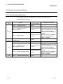
[Design Instructions]
!
CAUTION
• The user should take necessary measures when the PLC system must be secured against
illegal access from external devices via the Internet.
A-1
A-1
• CONDITIONS OF USE FOR THE PRODUCT •
(1) Mitsubishi programmable controller ("the PRODUCT") shall be used in conditions;
i) where any problem, fault or failure occurring in the PRODUCT, if any, shall not lead to any major or
serious accident; and
ii) where the backup and fail-safe function are systematically or automatically provided outside of the
PRODUCT for the case of any problem, fault or failure occurring in the PRODUCT.
(2) The PRODUCT has been designed and manufactured for the purpose of being used in general
industries.
MITSUBISHI SHALL HAVE NO RESPONSIBILITY OR LIABILITY (INCLUDING, BUT NOT LIMITED
TO ANY AND ALL RESPONSIBILITY OR LIABILITY BASED ON CONTRACT, WARRANTY, TORT,
PRODUCT LIABILITY) FOR ANY INJURY OR DEATH TO PERSONS OR LOSS OR DAMAGE TO
PROPERTY CAUSED BY the PRODUCT THAT ARE OPERATED OR USED IN APPLICATION NOT
INTENDED OR EXCLUDED BY INSTRUCTIONS, PRECAUTIONS, OR WARNING CONTAINED IN
MITSUBISHI'S USER, INSTRUCTION AND/OR SAFETY MANUALS, TECHNICAL BULLETINS AND
GUIDELINES FOR the PRODUCT.
("Prohibited Application")
Prohibited Applications include, but not limited to, the use of the PRODUCT in;
y Nuclear Power Plants and any other power plants operated by Power companies, and/or any other
cases in which the public could be affected if any problem or fault occurs in the PRODUCT.
y Railway companies or Public service purposes, and/or any other cases in which establishment of a
special quality assurance system is required by the Purchaser or End User.
y Aircraft or Aerospace, Medical applications, Train equipment, transport equipment such as Elevator
and Escalator, Incineration and Fuel devices, Vehicles, Manned transportation, Equipment for
Recreation and Amusement, and Safety devices, handling of Nuclear or Hazardous Materials or
Chemicals, Mining and Drilling, and/or other applications where there is a significant risk of injury to
the public or property.
Notwithstanding the above, restrictions Mitsubishi may in its sole discretion, authorize use of the
PRODUCT in one or more of the Prohibited Applications, provided that the usage of the PRODUCT is
limited only for the specific applications agreed to by Mitsubishi and provided further that no special
quality assurance or fail-safe, redundant or other safety features which exceed the general
specifications of the PRODUCTs are required. For details, please contact the Mitsubishi
representative in your region.
A-2
A-2
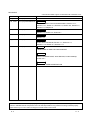
REVISIONS
* The manual number is given on the bottom left of the back cover.
Print Date
* Manual Number
May, 2004
Jul., 2004
SH (NA) 080465ENG-A
SH (NA) 080465ENG-B
Revision
First edition
Correction
About the Generic Terms and Abbreviations, Section 2.1.1,
Section 2.3.1, Section 4.3, Section 5.4, Section 6.2, Section 7.2,
Section 8.1, Chapter 10
Oct., 2004
SH (NA) 080465ENG-C
Jun., 2008
SH (NA) 080465ENG-D
Correction
Section 5.3, Section 5.4, Section 8.1
Correction
Section 9.2
Sep., 2008
SH (NA) 080465ENG-E
Correction
How to Use This Manual, Section 1.1, Section 2.3.1,
Section 5.1 to Section 5.4, Section 9.1.1
Nov., 2009
SH (NA) 080465ENG-F
Addition
CONDITIONS OF USE FOR THE PRODUCT
Correction
SAFETY PRECAUTIONS, About Manuals, Product Makeup,
Section 4.2.1
Deletions
SOFTWARE USER REGISTRATION
Japanese Manual Version SH-080437-G
This manual confers no industrial property rights or any rights of any other kind, nor does it confer any patent
licenses. Mitsubishi Electric Corporation cannot be held responsible for any problems involving industrial property
rights which may occur as a result of using the contents noted in this manual.
© 2004 MITSUBISHI ELECTRIC CORPORATION
A-3
A-3
INTRODUCTION
Thank you for choosing the Mitsubishi MELSOFT series Integrated FA software.
Read this manual and make sure you understand the functions and performance of MELSOFT series
thoroughly in advance to ensure correct use.
Please make this manual available to the end user.
CONTENTS
SAFETY PRECAUTIONS..............................................................................................................................A- 1
CONDITIONS OF USE FOR THE PRODUCT ............................................................................................A- 2
REVISIONS ....................................................................................................................................................A- 3
CONTENTS....................................................................................................................................................A- 4
About Manuals ...............................................................................................................................................A- 7
How to Use This Manual................................................................................................................................A- 8
About the Generic Terms and Abbreviations ...............................................................................................A–11
Product Makeup ............................................................................................................................................A–12
1. OVERVIEW
1- 1 to 1- 6
1.1 Features ................................................................................................................................................... 1- 1
1.2 About Automatic Operation and Manual Operation................................................................................ 1- 5
2. SYSTEM CONFIGURATION
2- 1 to 2-26
2.1 Device List for Server (personal computer) side..................................................................................... 2- 1
2.1.1 Connection from the serial/USB port ................................................................................................ 2- 2
2.1.2 Connection from the interface boards .............................................................................................. 2- 7
2.1.3 System equipment lists ..................................................................................................................... 2- 9
2.1.4 Connection from the PC CPU module.............................................................................................. 2-13
2.1.5 Connection from the Web server module......................................................................................... 2-19
2.2 Network Connection Method ................................................................................................................... 2-20
2.2.1 Connection configuration .................................................................................................................. 2-20
2.2.2 Connection configuration devices..................................................................................................... 2-21
2.3 Operating Environment ............................................................................................................................ 2-22
2.3.1 Server (personal computer) .............................................................................................................. 2-22
2.3.2 Personal computer ............................................................................................................................ 2-25
3. FUNCTION LIST
3- 1 to 3- 2
3.1 Server (Personal Computer) Function List.............................................................................................. 33.2 Personal Computer Side Function List.................................................................................................... 33.2.1 Monitor functions ............................................................................................................................... 33.2.2 Functions to cut off server (personal computer) line from personal computer ............................... 3-
A-4
A-4
1
2
2
2
4. PRE-OPERATION SETTINGS AND PROCEDURES
4- 1 to 4- 15
4.1 Server (Personal Computer) Setting Procedure ..................................................................................... 4- 2
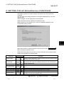
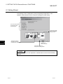
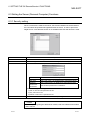
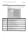
4.2 INSTALLATION AND UNINSTALLTION ................................................................................................ 4- 4
4.2.1 Installation.......................................................................................................................................... 4- 4
4.2.2 Uninstallation ..................................................................................................................................... 4- 9
4.3 Installing the USB Driver.......................................................................................................................... 4-11
4.4 Personal Computer Setting Procedure ................................................................................................... 4-15
5. INSTALLATION OF WEB SERVER SOFTWARE
5- 1 to 5-13
5.1 Windows 98 ............................................................................................................................................ 55.2 Windows NT 4.0 ..................................................................................................................................... 55.3 Windows 2000 (Professional) ................................................................................................................ 55.4 Windows XP (Professional) ................................................................................................................... 5R
R
R
R
6. SETTING THE GX RemoteService-I FUNCTIONS
1
3
5
9
6- 1 to 6-20
6.1 Setting Wizard .......................................................................................................................................... 6- 2
6.2 Main Screen ............................................................................................................................................. 6- 3
6.3 Setting the Server (Personal Computer) Functions ................................................................................ 6- 5
6.3.1 Security setting .................................................................................................................................. 6- 5
6.3.2 E-mail setting..................................................................................................................................... 6- 6
6.3.3 Network setting.................................................................................................................................. 6- 8
6.3.4 PLC type setting ................................................................................................................................ 6-10
6.3.5 Connection setup .............................................................................................................................. 6-11
6.3.6 Device range setting ......................................................................................................................... 6-15
6.3.7 Tag setting......................................................................................................................................... 6-16
6.3.8 Automatic operation setting .............................................................................................................. 6-18
6.3.9 Device display format setting............................................................................................................ 6-20
7. ABOUT THE PERSONAL COMPUTER
7- 1 to 7- 6
7.1 List of Personal Computer Setting Items................................................................................................. 77.2 Providing Tag Display .............................................................................................................................. 77.3 Monitoring the Devices ............................................................................................................................ 77.4 Setting the Server (Personal Computer) Line Connection ..................................................................... 78. GETTING STARTED WITH GX RemoteService-I (Web function)
1
3
4
6
8- 1 to 8-17
8.1 Setting GX RemoteService-I to the Server (Personal Computer).......................................................... 8- 1
8.2 Varying of Monitor Devices and Arrival of E-mail.................................................................................... 8-12
8.3 Receiving E-mail and Looking at Devices on Personal Computer......................................................... 8-13
8.3.1 Until looking at tag............................................................................................................................. 8-13
8.3.2 Until looking at devices ..................................................................................................................... 8-15
A-5
A-5
9. MELSOFT CONNECTION FUNCTION
9- 1 to 9- 7
9.1 Using the MELSOFT connection function............................................................................................... 99.1.1 When the server is personal computer/PC CPU module ................................................................ 99.1.2 When the server is Web server module ........................................................................................... 99.2 Application example of the MELSOFT connection function ................................................................... 910. TROUBLESHOOTING
APPENDICES
1
1
4
5
10- 1 to 10- 3
App- 1 to App- 2
APPENDIX 1 RESTRICTIONS..................................................................................................................App- 1
INDEX
A-6
Index- 1 to Index- 2
A-6
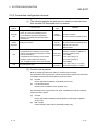
About Manuals
The following lists the manuals for this software package.
Refer to the following table when ordering manuals.
Related Manuals
Manual Number
(Model Code)
Manual Name
Web Server Module User’s Manual
Describes the system configuration, specifications, functions, dedicated instructions and troubleshooting
of Web server module.
SH-080320E
(13JR58)
(Sold separately)
GX Developer Version 8 Operating Manual
Describes the GX Developer functions including programming, printing-out, monitoring and debugging.
SH-080373E
(13JU41)
(Sold separately)
GX Explorer Version 2 Operating Manual
SH-080464ENG
(13JU49)
Describes the system configuration, functions and operations of GX Explorer.
(Sold separately)
Note:The Operating Manuals are included on the CD-ROM of the software package in a PDF file format.
Manuals in printed form are sold separately for single purchase. Order a manual by quoting the manual
number (model code) listed in the table above.
A-7
A-7
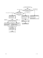
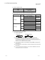
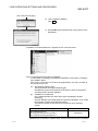
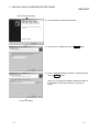
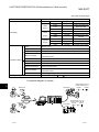
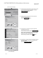
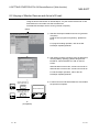
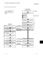
How to Use This Manual
"How to Use This Manual" is described purpose by purpose for use of GX
RemoteService-I. Refer to the following description and use this manual.
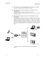
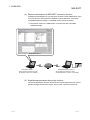
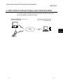
This system is divided into a personal computer and a server (personal computer).
The system can be introduced smoothly by making actual setting while checking the
purposes and setting sequence in the following flowchart.
Personal computer side
Personal computer
Server (Personal computer) side
Server (personal computer)
Internet
Intranet
PC CPU module
Mobile phone
Web server module (QJ71WS96)
For the server (personal computer) setting, set the automatic or manual operation
mode.
The personal computer side setting is required.
A-8
A-8
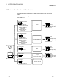
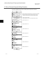
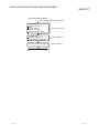
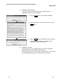
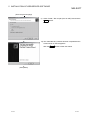
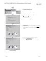
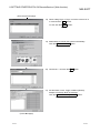
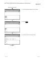
Use GX RemoteService-I
Use the Web function.
Server (personal computer) side
Automatic
operation mode
Set the server
(personal computer) or
personal computer
side setting
Use the Web function
or MELSOFT connection
function
Personal computer side
Grasp the setting items
and procedure on the
personal computer.
Prepare the personal
computer to be used on
the personal computer side.
Refer to Section 4.1
Refer to Section 4.4
Select the operation
mode
Manual
operation mode
Set the GX RemoteService-I
functions corresponding to
automatic operation
Set the GX RemoteService-I
functions corresponding to
manual operation
Refer to Chapter 6
Refer to Chapter 6
Use the MELSOFT
connection function.
Use the MELSOFT connection
function to access the PLC CPU
through the server
(personal computer).
Refer to Chapter 9
Personal computer side
functions
Refer to Chapter 7
Operation start
Operation method
Getting started with
GX RemoteService-I!
Refer to Chapter 8
Operation start
A-9
A-9
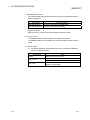
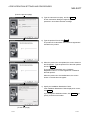
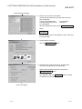
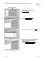
(1) When you want to know features or automatic or manual operation
(Section 1.1, Section 1.2)
Section 1.1 gives the features.
Section 1.2 describes automatic operation and manual operation.
(2) When you want to know the operating environment of GX
RemoteService-I (Section 2.3)
Describes the specifications of the personal computer used on the server
(personal computer) side.
(3) When you want to know the initial setting of the server (personal
computer) and personal computer (Section 4.1, Section 4.2)
Describes the procedures for setting the personal computer used on the server
(personal computer) side and the personal computer used on the personal
computer side.
(4) When you want to know the functions set with the server
(Chapter 6)
Provides the detailed explanation of the functions to be set.
Also gives the explanation of the easy and convenient Wizard for use.
(5) When you want to know the functions of the personal computer
(Section 7.1 to Section 7.4)
Describes the procedure for monitoring devices and comments from the personal
computer.
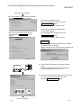
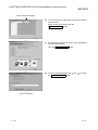
(6) When you want to operate GX RemoteService-I (Chapter 8)
Explains the procedures for setting the server (personal computer), sending email and making access from the personal computer to the server (personal
computer).
(7) When you want to know the MELSOFT connection function
(Chapter 9)
Describes how to access the PLC CPU through the server (personal computer)
from the client (personal computer) in which a MELSOFT connection functioncompatible software package*1 is installed, and provides the application
examples.
*1: GX Explorer Version 2 is a MELSOFT connection function-compatible
software package.
(8) When you want to know the actions to be taken at occurrence of
problems (Chapter 10)
Describes the troubleshooting to avoid trouble.
(9) When you want to know restrictions (Appendices)
Describes the restrictions on use of GX RemoteService-I.
A - 10
A - 10
About the Generic Terms and Abbreviations
Unless otherwise specified, this manual uses the following generic terms and
abbreviations to describe GX RemoteService-I.
Generic Term/Abbreviation
GX RemoteService-I
GX Explorer
PWS
IIS
Web server software
Windows 2000
WindowsNT 4.0
Description
Generic term for the product types SW2D5C-RAS-E, SW2D5C-RAS-EA.
Generic term for the product types SW2D5C-EXP-E, SW2D5C-EXP-EA.
Generic term for Personal Web Server.
Generic term for Internet Information Server.
Generic term for Personal Web Server, Internet Information Server, Peer Web Service.
Microsoft Windows 2000 Professional Operating System.
Microsoft WindowsNT Workstation 4.0 Operating System.
Microsoft Windows 98 Operating System.
Windows 98
Microsoft Windows 98 Second Edition Operating System.
Windows XP
Microsoft Windows XP Professional Operating System.
Microsoft Windows 98 Operating System.
Microsoft Windows 98 Second Edition Operating System.
Microsoft WindowsNT Workstation 4.0 Operating System.
Windows
Microsoft Windows 2000 Operating System.
Microsoft Windows XP Professional Operating System.
Provider
Internet Service Provider (ISP).
Personal computer/PC CPU module/Web server module in which GX RemoteService-I
Sever
Version 2 is installed.
PC CPU module
MELSEC-Q series-compatible PC CPU module (CONTAC CO., Ltd.)
Web server module
QJ71WS96 Web server module.
Generic term for A0J2H,A1S,A1FX,A1SJ,A1SH,A1SJH,A1N,A2C,A2CJ,A2N(S1),A2S,
A2SH,A3N.
ACPU
Including PLC CPU modules with MELSECNET datalink functions, QCPU (A mode) and
motion controller (SCPU).
AnACPU
Generic term for A2A,A2A-S1,A3A,A2AP21/R21,A2AP21/R21-S1,A3AP21/R21.
AnUCPU
Generic term for A2U,A2U-S1,A3U,A4U,A2US,A2US-S1,A2USH-S1.
QCPU (A mode)
Generic term for Q02(H)-A,Q06H-A.
QnACPU
Generic term for Q2A,Q2AS(H),Q2AS1,Q2AS(H)S1,Q3A,Q4A,Q4AR.
QCPU (Q mode)
Generic term for Q00J,Q00,Q01,Q02(H),Q06H,Q12H,Q12PH,Q25H,Q25PHCPU.
FXCPU
Generic term for FX0,FX0S,FX0N,FX1,FX2,FX2C,FX1S,FX1N,FX1NC,FX2N,FX2NC.
For
Generic term for A1SJ71C24-R2,A1SJ71C24-R4,A1SJ71C24-PRF,A2CCPUC24,
Computer link
A series
A2CCPUC24-PRF,A1SCPUC24-R2,AJ71C24-S,AJ71C24-S8.
Unit
For AnU
Generic term for AJ71UC24,A1SJ71UC24-R2,A1SJ71UC24-R4,A1SJ71UC24-PRF.
For
Generic term for AJ71QC24,AJ71QC24-R2,AJ71QC24-R4,AJ71QC24N,A1SJ71QC24,
Serial
QnA series A1SJ71QC24-R2,AJ71QC24N-R2,AJ71QC24N-R4,A1SJ71QC24N,A1SJ71QC24N-R2.
communication
For
unit
Generic term for QJ71C24,QJ71C24-R2,QJ71C24N,QJ71C24N-R2,QJ71C24N-R4.
Q series
C24
Computer link module, Serial Communication module.
QE71
Generic term for AJ71QE71AJ71QE71-B2AJ71QE71-B5A1SJ71QE71-B5.
Generic term for AJ71E71-S3,A1SJ71E71-B2-S3,A1SJ71E71-B5-S3,A1SJ71E71E71
B2,A1SJ71E71-B5.
Q series-compatible E71
Generic term for QJ71E71,QJ71E71-B2,QJ71E71-100.
Generic term for A70BDE-J71QLP23/A70BDE-J71QLP23G/A70BDEMELSECNET/10 board
J71QLR23/A70BDE-J71QBR13 MELSECNET/10 interface board.
Generic term for Q80BD-J71LP21-25/Q80BD-J71LP21G(E)/Q80BD-J71BR11
MELSECNET/H board
MELSECNET/H interface board.
Ethernet board
Ethernet PC card, Ethernet I/F board.
CC-Link board
Generic term for A80BDE-J61BT11/A80BDE-J61BT13 CC-Link interface board.
CPU board
Generic term for A80BDE-A2USH-S1 PLC CPU board.
R
R
R
R
R
R
R
R
R
R
R
R
R
R
R
R
R
R
R
A - 11
R
R
R
R
R
R
A - 11
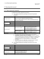
Product Makeup
GX RemoteService-I are made up of the following products.
Type
Product Name
GX RemoteService-I Version 2 (1-license product)
SW2D5C-RAS-E(V)
(CD-ROM)
License agreement
1
End-user software license agreement
1
Method of installing the MELSOFT series
1
Software registration notice
1
GX RemoteService-I Version 2 (Multiple license product)
(CD-ROM)
License agreement
SW2D5C-RAS-E(V)A
Quantity
1
End-user software license agreement
1
1
n*
1
Method of installing the MELSOFT series
1
Software registration notice
1
*1: The number of included license agreements is equivalent to the number of licenses.
A - 12
A - 12
1 OVERVIEW
MELSOFT
1. OVERVIEW
This manual explains the system configuration, functions, setting method and
operations of MELSEC PLC-compatible remote access tool, GX RemoteService-I.
1.1 Features
GX RemoteService-I is the software package (needed to be installed in the server) that
makes a connection between the PLC CPU at the site and the client (personal
computer or mobile phone) in a remote location via the Internet (or Intranet).
GX RemoteService-I includes the Web function and MELSOFT connection function,
which can realize the excellent remote maintenance of PLC CPU.
• Web function
Notifies of the PLC CPU device status by sending an e-mail to a mobile phone or
personal computer.
Also, enables the PLC CPU device status or relevant comments to be checked
from Web browser of a mobile phone or personal computer.
• MELSOFT connection function
1
Connects to the PLC CPU from the software package* in the client (personal
computer) via the Internet (or Intranet).
Also, enables the PLC CPU, which is in a remote location from the client (personal
2
computer), to be maintained using the software package* .
*1: GX Explorer Version 2 is a MELSOFT connection function-compatible software
package.
*2: For usable functions, refer to the operating manual of the software package
used.
1-1
1-1
1
1 OVERVIEW
1
Web function
MELSOFT
Applications needed to be installed in the server (personal computer)
GX RemoteService-I Version 2 (this product)
Web browser (supplied by Microsoft ®)
Internet Explorer 6.0 or later.
Applications needed to be installed in the server (personal computer)
for use of the Web function
Web server software (supplied by Microsoft ®)
Personal Web Server 4.0 or later (PWS) : Windows® 98
Internet Information Server 5.0 or later (IIS): Windows® 2000/XP
: WindowsNT® 4.0
Peer Web Service 4.0 or later
Internet
Intranet
MELSOFT connection function
GX Explorer Version 2
1-2
1-2
1 OVERVIEW
MELSOFT
(1) PLC CPU can be monitored/diagnosed via the Internet or Intranet
The personal computer allows you to know the PLC status.
(2) This system can be introduced without any modification to the
existing system
No dedicated special modules are required to use this product.
In addition, you need not change the parameter values since this product does
not require I/O points.
(3) Wide range of operating environments (Compatible with Internet
and Intranet)
A Windows-based personal computer, PC CPU module and Web server module
are applicable for the operating environment of the server. Also, the following
networks, Internet and Intranet are applicable. In addition, the connection
methods are selectable from analogue, mobile phone, DSL and LAN. With this
wide range of operating environments, the system can be constructed according
the needs, and GX RemoteService-I can be introduced into the existing system
easily.
Server (personal computer)
analogue
mobile phone
Internet
Intranet
DSL
LAN
PC CPU module
Web server module (QJ71WS96)
For Internet connection, a contract with ISP (Internet Service Provider) is
required.
1-3
1-3
1 OVERVIEW
MELSOFT
(4) Remote maintenance by MELSOFT connection function
Installing GX RemoteService-I into the server enables remote maintenance of the
PLC CPU from the client (personal computer in which MELSOFT connection1
compatible software package* is installed) via the Internet or intranet.
*1: GX Explorer Version 2 is a MELSOFT connection function-compatible
software package.
GX Explorer Version 2
Internet
Intranet
GX Explorer Version 2
Client (personal computer in which
GX Explorer Version 2 is installed)
GX RemoteService-I Version 2
Server (personal computer in which
GX RemoteService-I Version 2 is installed)
(5) Illegal access prevention by security function
The user authentication function checks the user name and password in order to
prevent an illegal access to the server, when a client connects to the server.
1-4
1-4
1 OVERVIEW
MELSOFT
1.2 About Automatic Operation and Manual Operation
GX RemoteService-I allows you to select the automatic or manual operation mode.
The features of the automatic and manual operation modes are explained below. They
will be helpful for you when constructing a system.
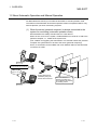
(1) When the server (personal computer) is always connected to the
system for monitoring (automatic operation mode)
GX RemoteService-I always monitors the PLC CPU devices.
When an error occurs in the system, GX RemoteService-I sends an e-mail to the
personal computer, i.e., notifies of the system error.
(The condition for triggering the transmission of e-mail that notifies the personal
computer of a system fault is to be set to the server (personal computer).)
Hence, a serviceman can be notified of an error definition within a short time after
occurrence of a fault.
Serviceman
Displays the PLC's device value
and comment/tag by a single click
Internet
Intranet
Belt conveyor
stopped on line A!
System diagnosis is
enabled by using the
device with comments.
GX RemoteService-I
detects a system error
and notifies a serviceman
by sending e-mail.
Serviceman
1-5
1-5
1 OVERVIEW
MELSOFT
(2) When an operator judges a fault and contacts a serviceman
(manual operation mode)
If a fault has occurred in the system, an operator can make judgment to notify a
serviceman of the faulty condition.
The serviceman can diagnose the actual system from a remote location to run
more in-depth diagnostics.
Serviceman
Displays the PLC's device value
and comment/tag by a single click
Operator
sends e-mail
to serviceman.
Internet
Intranet
Belt conveyor
stopped on line A!
Operator
System diagnosis is
enabled by using the
device with comments.
Serviceman
1-6
1-6
2 SYSTEM CONFIGURATION
MELSOFT
2. SYSTEM CONFIGURATION
2.1 Device List for Server (personal computer) side
This section explains the system configuration that uses GX RemoteService-I.
Refer to Section 2.1.1, Section 2.1.2, Section 2.1.3 and Section 2.1.4 for the system
device lists of the server (personal computer) side.
Refer to Section 2.3.2 for the system device list of the personal computer side.
Personal computer side
Personal computer
Mobile phone
Refer to Section 2.3.2.
Server (personal computer) side
Internet
Intranet
The following environment is required for the server (personal computer).
1. You need to make a contract with a provider.
2. Applications needed to be installed in the server (personal computer)
(1) GX RemoteService-I Version 2 (this product)
(2) Web browser (supplied by Microsoft )
Internet Explorer 6.0 or later.
3. Applications needed to be installed in the server (personal computer)
for use of the Web function
(1) Web server software (supplied by Microsoft )
Personal Web Server 4.0 or later (PWS) : Windows ®98
Peer Web Service 4.0 or later
: WindowsNT ®4.0
Internet Information Server 5.0 or later (IIS): Windows ® 2000/XP
Refer to Section 2.1.1.
Refer to Section 2.1.2.
Refer to Section 2.1.3.
Refer to Section 2.1.4.
Refer to Section 2.3.1.
2-1
2-1
2
2 SYSTEM CONFIGURATION
MELSOFT
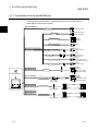
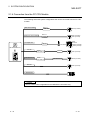
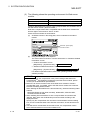
2.1.1 Connection from the serial/USB port
The following shows the system configuration that can be connected from the
serial/USB port of personal computer.
USB communication
2
*1
USB cable
QCPU (Q mode)
*2
QC30R2
QCPU (Q mode)
QCPU (A mode)
*3
Converter/cable
ACPU
QnACPU
*3
Converter/cable
Serial port communication
FXCPU
*4
*3
Converter/cable
*5
Cable
*5
*6
Converter/cable
*4
*6
Converter/cable
*7
Computer link
RS-232
C24
FXCPU
(FX1S/FX1N/FX2N)
FXCPU
(FX1S/FX1N/FX2N
/FX1NC/FX2NC)
FXCPU
(FX0/FX0S/FX1S/FXON
/FX1N/FX2N/FX1NC/FX2NC)
FXCPU
(FX1S/FX1N/FX2N)
ACPU
QnACPU
QCPU (Q mode)
QCPU (A mode)
GX RemoteService-I
CC-Link (via G4)
*3
Converter/cable
CC-Link
G4 module
G4-S3 module
MELSECNET(II)
*3
Converter/cable
Remote station
Remote unit
Master station
Remote station
Remote unit
Control station
MELSECNET/10
MELSECNET/H
2-2
ACPU
QnACPU
QCPU (Q mode)
QCPU (A mode)
*3
Converter/cable
2-2
2 SYSTEM CONFIGURATION
MELSOFT
*1: About the USB cable (QCPU (Q mode) compatible)
(1) Usable when either of Windows 98, Windows 2000 Professional or
Windows XP Professional is used, and the USB driver is installed.
R
R
R
(2) Unusable for Windows 95, WindowsNT 4.0.
R
R
(3) Use of the USB cable allows only one PLC CPU to be connected.
(4) Use the UBS cable which conforms to the USB Standard Rev. 1.1.
(5) The following indicates the precautions for and restrictions on
communications made using the USB cable.
1) A communication error may occur if you set the resume function,
suspend setting, power saving function or standby mode of the server
(personal computer) to make communications with the PLC CPU.
Hence, do not set any of the above functions when making
communications with the PLC CPU.
2) Frequently connecting/disconnecting the USB cable, resetting the PLC
CPU or switching power OFF/ON during communications with the PLC
CPU may cause a communication error from which the system may not
be recovered.
Where possible, therefore, exit from GX RemoteService-I before
connecting/disconnecting the USB cable, resetting the PLC CPU or
switching power OFF/ON.
If the system cannot be recovered from the communication error,
completely disconnect the USB cable once and reconnect it after more
than five seconds have elapsed. (An error may occur at the first
communication after this operation, but the system will function properly
after the second time and later.)
3) A communication error may occur depending on the combination of the
server (personal computer) model, USB cable and others. In that case,
refer to the messages and perform operation again.
*2: About the cable (QCPU (Q mode), QCPU(A mode) compatible)
For communication in 115.2/57.6kbps
Fast communication cannot be made if the Personal computer used is not
compatible with the communication speed of 115.2/57.6kbps.
If a communication error occurs, reduce the baud rate setting and restart
communication.
The following cable has been confirmed by Mitsubishi Electric that it will work
properly.
Using the cable of Mitsubishi Electric make
RS-232 cable
QC30R2 (when Personal computer connector is D-sub, 9-pin)
2-3
2-3
2 SYSTEM CONFIGURATION
MELSOFT
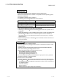
*3: About the converter/cable (ACPU, QnACPU, FXCPU compatible)
(1) Using the products of Mitsubishi Electric make.
Personal computer Side
(RS-232 cable)
RS-232/RS-422
Converter
PLC Side
(RS-422 cable)
For ACPU, QnACPU, FX1/FXU, FX2CCPU
FX-232AW
FX-422CAB (0.3m)
FX-422CAB-150 (1.5m)
F2-232CAB-1
(when Personal computer connector is D-sub,
FX-232AWC
9-pin)
FX-232AWC-H
(FX series only)
For FX0/FX0S/FX0N/FX1S/FX1N/FX2N/FX2NCCPU
FX-422CABO (1.5m)
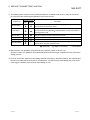
• How to identify compatibility of the F2-232CAB and F2-232CAB-1 cables with
the ACPU and QnACPU
Check the indication of the model label attached to the cable.
Incompatible products
Compatible products (with indication of F/FX/A)
F2-232CAB
Y990C
F2-232CAB(F/FX/A)
Y990C
F2-232CAB-1
Y990C
F2-232CAB-1(F/FX/A)
Y990C
• When connecting to FX series, make sure to use the device in the above table.
Example of connecting IBM-PC/AT-compatible personal computer and QnACPU using EX-232AW(C)
IBM-PC/AT-compatible
personal computer
QnACPU
*1
F2-232CAB-1
FX-232AW(C)
FX-422CAB(-150)
*1: A straight cable (connector) for converting between D sub 9 pin D sub 25 pin might be required, depending on the
cable.
Use the conversion cable by referring to the manual of the IBM-PC/AT-compatible personal computer.
(IBM-PC/AT-compatible personal computer mentioned above RS-232 cable for converter connection)
F2-232CAB-1 (D sub 9 pin D sub 25 pin)
REMARK
Access can be made to the PLC CPU through GOT-F900 (instead of a converter).
For details, refer to the manual or catalog of the above product.
2-4
2-4
2 SYSTEM CONFIGURATION
MELSOFT
*4: Function expansion board
Series
Function expansion board
FX2N
FX2N-422-BD
FX1S, FX1N
FX1N-422-BD
*5: RS-232 cable and function expansion board (special adapter)
Shape of serial port for
personal computer
Series
FX2N
FX1NC,
FX2NC
D sub 9 pin
FX1S,
FX1N
FX2N
FX1NC,
FX2NC
D sub 25 pin
FX1S,
FX1N
Required function expansion board
and special adapter
FX0N-232ADP + FX2N-CNV-BD
FX2N-232-BD
FX2NC-232ADP + FX2N-CNV-BD
FX0N-232ADP
FX2NC-232ADP
FX0N-232ADP + FX1N-CNV-BD
FX1N-232-BD
FX2NC-232ADP + FX1N-CNV-BD
FX0N-232ADP + FX2N-CNV-BD
FX2N-232-BD
FX2NC-232ADP + FX2N-CNV-BD
FX0N-232ADP
FX2NC-232ADP
FX0N-232ADP + FX1N-CNV-BD
FX1N-232-BD
FX2NC-232ADP + FX1N-CNV-BD
RS-232 cable
F2-232CAB-1
FX-232CAB-1
F2-232CAB-1
FX-232CAB-1
F2-232CAB-1
FX-232CAB-1
F2-232CAB
F2-232CAB-1
F2-232CAB
F2-232CAB-1
F2-232CAB
F2-232CAB-1
*6: Converter/cable (FXCPU compatible)
(1) System configuration
FX-USB-AW
USB cable (packed)
(2) When Windows 98, Windows Me, Windows 2000 Professional,
Windows XP Professional or Windows XP Home Edition is used, the
converter/cable is available if the driver on the CD-ROM packed with the FXUSB-AW or FX3U-USB-BD has been installed.
R
R
R
R
R
(3) The converter and cable are unavailable for Windows 95 or Windows NT
Workstation 4.0.
R
R
(4) On GX Developer, choose [Online] - [Transfer setup] and set the serial COM
port number.
(5) For the precautions and restrictions on use of the FX-USB-AW, refer to the
manual packed with the FX-USB-AW.
2-5
2-5
2 SYSTEM CONFIGURATION
MELSOFT
*7: Computer link
The program that uses V, Z (Indexing) cannot be monitored if routing through a
computer link module when A Series is used.
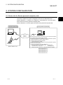
POINT
• Before handling the RS-422 interface conversion cable/converter, please read its
specifications, precautions, etc. carefully in the manual of the corresponding
product and handle it correctly.
• When disconnecting or reconnecting the conversion cable/converter that receives
5VDC power from the RS-422 interface, switch power off on the PLC CPU side
before starting work.
• When disconnecting or reconnecting the peripheral device or conversion cable
that does not receive 5VDC power from the RS-422 interface (whose power is
supplied from an external power supply), be sure to use an earth band or touch a
grounded metal object, etc. before starting work to discharge static electricity from
the cable, human body, etc. After that, handle it in the following procedure.
1) Switch power off on the personal computer side.
2) Power off the conversion cable/converter. When it has an FG terminal, ground
it.
3) Connect/disconnect the conversion cable/converter between the personal
computer and PLC CPU.
4) Power on the conversion cable/converter.
5) Power on the personal computer.
6) Start up the software package.
2-6
2-6
2 SYSTEM CONFIGURATION
MELSOFT
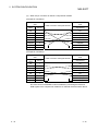
2.1.2 Connection from the interface boards
The following system configuration is made up by connection from the interface
boards.
Refer to the corresponding board manuals for the way to connect the boards and
install the drivers.
*1
MELSECNET/10 board
A70BDE-J71QLP23
(Optical loop)
A70BDE-J71QLP23GE
(Optical loop)
A70BDE-J71QBR13
(Coaxial bus)
A70BDE-J71QLR23
(Coaxial loop)
Driver
SW3DNF-MNET10
ACPU
QnACPU
QCPU(Q mode)
QCPU(A mode)
Other satation PLC
MELSECNET/H board
Q80BD-J71BR11
(Coaxial bus)
Q80BD-J71LP21-25
(Optical loop)
Q80BD-J71LP21G
(Optical loop)
Q80BD-J71LP21GE
(Optical loop)
Driver
SW0DNC-MNETH-B
ACPU
QnACPU
QCPU(Q mode)
QCPU(A mode)
Other satation PLC
*2
CC-Link board
Driver
GX RemoteService-I
A80BDE-J61BT11
A80BDE-J61BT13
SW4DNF-CCLINK-B
ACPU
QnACPU
QCPU(Q mode)
QCPU(A mode)
Other satation PLC
*3
Ethernet board
Commercially Ethernet board
Driver
Driver supplied with
commercially available
Ethernet board
ACPU
QnACPU
QCPU(Q mode)
QCPU(A mode)
Other satation PLC
CPU board
A80BDE-A2USH-S1
2-7
Driver
SW1DNF-ANU-B
2-7
2 SYSTEM CONFIGURATION
MELSOFT
*1: MELSECNET/10 board
The following table indicates the drivers that cannot be used with the specific
Operating Systems.
Driver Name
Operating Systems
SW3DNF-MNET10
Cannot be used with Windows Me/2000.
SW0DNC-MNETH-B
Cannot be used with Windows Me.
R
R
If a communications error takes place, an error code is indicated in the least
significant 4 digits.
Refer to the error code list of the MELSECNET/10 board manual.
*2: CC-Link board
The A80BDE-J61BT11 allows setting of the master/local station.
The A80BDE-J61BT13 is accessible only when local station setting has been
made.
*3: Ethernet board
(1) The following Ethernet boards/cards have been confirmed by Mitsubishi
Electric to operate properly.
Maker Name
3COM
Allied Telesis
TDK make
2-8
Model
Ethernet Link III LAN PC Card
Centre COM LA-PCM Ethernet PC Card LAN Adapter
RE2000 (ISA)
10BASE-T LAN card
(Model: LAN-CD021BX)
2-8
2 SYSTEM CONFIGURATION
MELSOFT
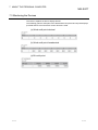
2.1.3 System equipment lists
(1)
The following list indicates module connectable from the serial port.
PC Series
Module Name
Module Model
Q00J, Q00, Q01, Q02(H), Q06H, Q12H, Q25H
PLC CPU module
Q Series
Q02(H)-A, Q06H-A
1
Serial communication module *
QJ71C24, QJ71C24-R2, QJ71C24N,
QJ71C24N-R2, QJ71C24N-R4
MELSECNET/H network remote I/O module
QJ72LP25, QJ72BR15
G4-S3 module
AJ65BT-G4-S3
Q2A, Q2AS(H), Q2AS1, Q2AS(H)S1, Q3A, Q4A,
PLC CPU module
Q4AR
AJ71QC24, AJ71QC24-R2, AJ71QC24-R4,
2
QnA Series
Serial communication module *
AJ71QC24N, A1SJ71QC24, A1SJ71QC24-R2,
AJ71QC24N-R2, AJ71QC24N-R4, A1SJ71QC24N,
A1SJ71QC24N-R2
MELSECNET/10 network remote I/O module
G4 module
AJ72QLP25, AJ72QBR15, A1SJ72QLP25,
A1SJ72QBR15
AJ65BT-G4, AJ65BT-G4-S3
A0J2H, A1S(S1), A1FX, A1SJ, A1SH, A1SJH,
A1N, A2C, A2CJ, A2N(S1)A2S(S1), A2SH(S1),
PLC CPU module
A3N, A2A(S1), A3A, A2U(S1), A2AS(S1),
A2AS-S30, A2AS-S60, A3U, A4U
AJ71UC24, A1SJ71UC24-R2, A1SJ71UC24-PRF,
A Series
A1SJ71C24-R2, A1SJ71C24-R4,
3
Computer link module *
A1SJ71C24-PRF, AJ71C24-S6, AJ71C24-S8,
A1SCPUC24-R2, A2CCPUC24,
A2CCPUC24-PRF, A1SJ71UC24-R4
MELSECNET/B data link remote I/O module
AJ72T25B, A1SJ72T25B
MELSECNET/10 data link remote I/O module
AJ72LP25, AJ72LP25, AJ72BR15
G4 module
AJ65BT-G4, AJ65BT-G4-S3
FX Series
PLC CPU module
MOTION (SCPU)
PLC CPU module
2-9
FX0(S), FX0N, FX1, FXU, FX2C, FX1S, FX1N, FX1N,
FX2N(C)
A171SH, A172SH, A173UH(S1), A273UH(S3)
2-9
2 SYSTEM CONFIGURATION
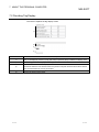
(2)
MELSOFT
The following table indicates the modules which can be connected from the
MELSECNET/10 or MELSECNET/H (MELSECNET/10 mode) board.
PC Series
Module Name
Q Series
QJ71LP21, QJ71LP21G, QJ71BR11, QJ71LP21-25, QJ71LP21S-25
QnA Series
AJ71QLP21, AJ71QBR11, A1SJ71QLP21, A1SJ71QBR11
A Series
AJ71LP21, AJ71BR11, A1SJ71LP21, A1SJ71BR11
(3)
The following table indicates the modules which can be connected from the
MELSECNET/H board.
PC Series
Q Series
Module Name
QJ71LP21, QJ71BR11, QJ71LP21-25
(4)
The following list indicates modules connectable from the CC-Link board.
PC Series
Q Series
Module Name
QJ61BT11, QJ61BT11N
QnA Series
AJ61QBT11, A1SJ61QBT11
A Series
AJ61BT11, A1SJ61BT11
(5)
The following list indicates modules connectable from the Ethernet board.
PC Series
Q Series
QnA Series
Module Name
QJ71E71, QJ71E71-B2, QJ71E71-100, QJ71E71-B5
AJ71QE71, AJ71QE71-B5, A1SJ71QE71-B2, A1SJ71QE71-B5, AJ71QE71N-T, A1SJ71QE71N-T,
AJ71QE71N-B5, A1SJ71QE71N-B5, AJ71QE71N-B2, A1SJ71QE71N-B2, AJ71QE71N-B5T,
A1SJ71QE71N-B5T
A Series
AJ71E71-S3, A1SJ71E71-B2-S3, A1SJ71E71-B5-S3, A1SJ71E71-B2, A1SJ71E71-B5,
AJ71E71N-B2, AJ71E71N-B5T, A1SJ71E71N-B2, A1SJ71E71N-B5, AJ71E71N-T, A1SJ71E71N-T,
AJ71E71N-B5, A1SJ71E71N-B5
2 - 10
2 - 10
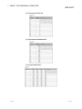
2 SYSTEM CONFIGURATION
MELSOFT
*1: When accessing the PLC CPU from the server (personal computer) through
a serial communication module (for Q series), note that some modules are
inapplicable for connection to a personal computer.
Even if a module cannot be directly connected to the server (personal
computer), it might be usable as "n"th device in the multidrop connection.
Type
QJ71C24
QJ71C24-R2
Interface
1:1
Connection
Multidropping
First module
"n"th module
RS-232C
RS-422/485
RS-232C
RS-232C
*2: The following table indicates whether the interfaces may be connected to
the personal computer when the PLC CPU is accessed from the personal
computer via the serial communication module (QC24).
If the module cannot be connected directly with the personal computer, it
may be usable as the "n"th module of multidropping.
Type
AJ71QC24
AJ71QC24N
AJ71QC24-R2
AJ71QC24N-R2
AJ71QC24-R4
AJ71QC24N-R4
A1SJ71QC24
A1SJ71QC24N
A1SJ71QC24-R2
A1SJ71QC24N-R2
2 - 11
Interface
1:1
Connection
Multidropping
First module
"n"th module
RS-232C
RS-422/485
RS-232C
RS-422/485
RS-232C
RS-232C
RS-232C
RS-232C
RS-422
RS-422/485
RS-422
RS-422/485
RS-232C
RS-422/485
RS-232C
RS-422/485
RS-232C
RS-232C
RS-232C
RS-232C
2 - 11
2 SYSTEM CONFIGURATION
MELSOFT
*3: About the computer link module
Note that when the PLC CPU is accessed from the personal computer via
the computer link module, the modules that may be connected directly with
the personal computer are limited.
If the module cannot be connected directly with the personal computer, it
may be usable as the "n"th module of multidropping.
Type
AJ71UC24
AJ71C24-S6
AJ71C24-S8
A1SJ71UC24-R2
Interface
1:1
Connection
Multidropping
First module
"n"th module
RS-232C
RS-422/485
RS-232C
RS-422
RS-232C
RS-422
RS-232C
A1SJ71C24-R2
RS-232C
A1SJ71UC24-PRF
RS-232C
A1SJ71C24-PRF
RS-232C
A1SJ71UC24-R4
RS-422/485
A1SJ71C24-R4
RS-422/485
A1SCPUC24-R2
RS-232C
RS-232C
A2CCPUC24
RS-422
RS-422/485
RS-232C
A2CCPUUC24-PRF
RS-422
RS-422/485
2 - 12
2 - 12
2 SYSTEM CONFIGURATION
MELSOFT
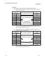
2.1.4 Connection from the PC CPU Module
The following shows the system configuration that can be connected from the PC CPU
module.
See 2.1.1
USB cable
USB communication
Serial port communication
Computer link
QCPU (Q mode)
See 2.1.1
QC30R2
QCPU (Q mode)
QCPU (A mode)
ACPU
QnACPU
QCPU (Q mode)
QCPU (A mode)
*1
RS-232
C24
GX RemoteService-I
CC-Link
MELSECNET/H
Driver
PPC-DRV-01
CC-Link
Driver
PPC-DRV-01
MELSECNET/H
QCPU (Q mode)
QCPU (Q mode)
Ethernet
QCPU (Q mode)
Q Sries Bus
Multiple CPU
POINT
The PC CPU module is applicable for the MELSOFT connection only.
2 - 13
2 - 13
2 SYSTEM CONFIGURATION
MELSOFT
*1: Examples of Wiring RS-232 Cable for Connection of C24 and Personal computer
A Series
(1) When a 25-pin connector is used in a computer link module
(Connection example 1)
Computer Link Module
Side
Signal
Pin No.
Name
GX RemoteService-I
Side
Signal Name
FG
1
FG
SD(TXD)
2
SD(TXD)
RD(RXD)
3
RD(RXD)
RS
4
RS
CS(CTS)
5
CS(CTS)
DSR(DR)
6
DSR(DR)
SG
7
SG
CD
8
CD
DTR(ER)
20
DTR(ER)
If the connection between the computer link module and the GX RemoteService-I
is made in the manner shown below, designate "without CD terminal check".
(Connection example 2)
Computer Link Module
Side
Signal
Pin No.
Name
GX RemoteService-I
Side
Signal Name
FG
1
FG
SD(TXD)
2
SD(TXD)
RD(RXD)
3
RD(RXD)
RS
4
RS
CS(CTS)
5
CS(CTS)
DSR(DR)
6
DSR(DR)
SG
7
SG
CD
8
CD
DTR(ER)
20
DTR(ER)
Buffer memory setting
CD terminal check (address 10Bh): Without check
DTR control (address 11Ah): Yes (C24-S8, UC24)
2 - 14
2 - 14
2 SYSTEM CONFIGURATION
(2)
MELSOFT
When a 9-pin connector is used in a computer link module
(Example of connection)
Computer Link Module
Side
Signal
Pin No.
Name
Cable Connection and Signal Direction
GX RemoteService-I
Side
Signal Name
CD
1
CD
RD(RXD)
2
RD(RXD)
SD(TXD)
3
SD(TXD)
DTR(ER)
4
DTR(ER)
SG
5
SG
DSR(DR)
6
DSR(DR)
RS(RTS)
7
RS(RTS)
CS(CTS)
8
CS(CTS)
(Example of connection)
Computer Link Module
Side
Signal
Pin No.
Name
Cable Connection and Signal Direction
GX RemoteService-I
Side
Signal Name
CD
1
CD
RD(RXD)
2
RD(RXD)
SD(TXD)
3
SD(TXD)
DTR(ER)
4
DTR(ER)
SG
5
SG
DSR(DR)
6
DSR(DR)
RS(RTS)
7
RS(RTS)
CS(CTS)
8
CS(CTS)
DC code control or DTR/DSR control is enabled by connecting the DTR and
DSR signals of the computer link module to an external device as shown above.
2 - 15
2 - 15
2 SYSTEM CONFIGURATION
MELSOFT
QnA Series
(1) When a 25-pin connector is used in a serial communication module
(a) Example of connection to an external device that allows the CD signal (No.
8 pin) to be turned ON/OFF
Serial communication
module Side
Signal
Pin No.
Name
FG
Cable Connection and Signal Direction
(Full-/Half-Duplex Communication)
1
GX RemoteService-I
Side
Signal Name
FG
SD(TXD)
2
SD(TXD)
RD(RXD)
3
RD(RXD)
RS
4
RS
CS(CTS)
5
CS(CTS)
DSR(DR)
6
DSR(DR)
SG
7
SG
CD
8
CD
DTR(ER)
20
DTR(ER)
DC code control or DTR/DSR control is enabled by connecting the QC24
(N) to an external device as shown above.
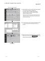
(b)
Example of connection to an external device that does not allow the CD
signal (No. 8 pin) to be turned ON/OFF
Serial communication
module Side
Signal
Pin No.
Name
FG
1
Cable Connection and Signal Direction
(Full-Duplex Communication)
GX RemoteService-I
Side
Signal Name
FG
SD(TXD)
2
SD(TXD)
RD(RXD)
3
RD(RXD)
RS
4
RS
CS(CTS)
5
CS(CTS)
DSR(DR)
6
DSR(DR)
SG
7
SG
CD
8
CD
DTR(ER)
20
DTR(ER)
DC code control or DTR/DSR control is enabled by connecting the QC24
(N) to an external device as shown above.
2 - 16
2 - 16
2 SYSTEM CONFIGURATION
(2)
MELSOFT
When a 9-pin connector is used in a serial communication module
(a) Example of connection to an external device that allows the CD (a)signal
(No. 1 pin) to be turned ON/OFF
Serial communication
module Side
Signal
Pin No.
Name
Cable Connection and Signal Direction
(Full- / Half-Duplex Communication)
GX RemoteService-I
Side
Signal Name
CD
1
CD
RD(RXD)
2
RD(RXD)
SD(TXD)
3
SD(TXD)
DTR(ER)
4
DTR(ER)
SG
5
SG
DSR(DR)
6
DSR(DR)
RS(RTS)
7
RS(RTS)
CS(CTS)
8
CS(CTS)
DC code control or DTR/DSR control is enabled by connecting the QC24
(N) to an external device as shown above.
(b)
Example of connection to an external device that does not allow the CD
signal (No. 1 pin) to be turned ON/OFF
Serial communication
module Side
Signal
Pin No.
Name
Cable Connection and Signal Direction
(Full-Duplex Communication)
GX RemoteService-I
Side
Signal Name
CD
1
CD
RD(RXD)
2
RD(RXD)
SD(TXD)
3
SD(TXD)
DTR(ER)
4
DTR(ER)
SG
5
SG
DSR(DR)
6
DSR(DR)
RS(RTS)
7
RS(RTS)
CS(CTS)
8
CS(CTS)
DC code control or DTR/DSR control is enabled by connecting the QC24
(N) to an external device as shown above.
2 - 17
2 - 17
2 SYSTEM CONFIGURATION
MELSOFT
Q Series
The connector specifications are indicated below.
Pin
Number
1
2
3
4
5
6
7
8
9
(1)
Signal Code
Signal Name
CD
RD (RXD)
SD (TXD)
DTR (ER)
SG
DSR (DR)
RS (RTS)
CS (CTS)
RI (CI)
Receive carrier detection
Receive data
Send data
Data terminal ready
Send ground
Data set ready
Request to send
Clear to send
Call indication
Signal Direction Q-compatible C24
↔ external device
Connection example which can turn ON/OFF CD signal (No. 1 pin)
Serial communication
module Side
Signal
Pin No.
Name
Cable Connection and Signal Direction
(Connection example for full duplex/half
duplex communication)
GX RemoteService-I
Side
Signal Name
CD
1
CD
RD (RXD)
2
RD (RXD)
SD (TXD)
3
SD (TXD)
DTR (ER)
4
DTR (ER)
SG
5
SG
DSR (DR)
6
DSR (DR)
RS (RTS)
7
RS (RTS)
CS (CTS)
8
CS (CTS)
RI (CI)
9
(2) Connection example which cannot turn ON/OFF CD signal (No. 1 pin)
Connection example for exercising DC code control or DTR/DSR control
Serial communication
module Side
2 - 18
Cable Connection and Signal Direction
(Connection example for full duplex
communication)
GX RemoteService-I
Side
Signal
Name
Pin No.
CD
1
CD
RD (RXD)
2
RD (RXD)
Signal Name
SD (TXD)
3
SD (TXD)
DTR (ER)
4
DTR (ER)
SG
5
SG
DSR (DR)
6
DSR (DR)
RS (RTS)
7
RS (RTS)
CS (CTS)
8
CS (CTS)
RI (CI)
9
2 - 18
2 SYSTEM CONFIGURATION
MELSOFT
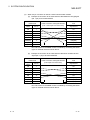
2.1.5 Connection from the Web server module
The following shows the system configuration that can be connected from the Web
server module.
Computer link
QCPU(Q mode)
GX RemoteService-I
MELSECNET/H
CF
CC-link
QCPU(Q mode)
QCPU(Q mode)
Web server module
(QJ71WS96)
Ethernet
QCPU(Q mode)
POINT
• For information on the compact flash card (TYPE I storage card that meets
CompactFlashTM specifications) supported by the Web server module, please
contact your local Mitsubishi representative.
• Make sure to use a compact flash card of 64MB or more for the Web server
module.
• Make sure to use the format function of the Web server module to format a
compact flash card. For details, refer to the Web server module user’s manual.
• When installing GX RemoteService-I into a compact flash card, specify only the
compact flash card drive in the destination selection dialog box. Do not add the
folder name after the drive name, as this will result in an error.
• The Web server module takes 90 seconds to start, if a compact flash card in
which GX RemoteService-I has been installed is set.
2 - 19
2 - 19
2 SYSTEM CONFIGURATION
MELSOFT
2.2 Network Connection Method
2.2.1 Connection configuration
The following describes the methods of connecting a server that uses GX
RemoteService-I to network.
Connection
method
Device
Sever ←→ Analogue modem
Automatic acquisition
of server IP address
Possible
Sever ←→ Broadband router ←→
Analogue modem
Possible depending on
the router
Sever ←→ Dial-up router
Possible depending on
the router
Sever ←→ Modem for mobile phone
+ Mobile phone
Possible
Sever ←→ Bridge type DSL modem
Possible
Analogue
Mobile
phone
Sever ←→ Broadband router ←→
Bridge type DSL modem
Possible depending on
the router
Sever ←→ Router type DSL modem
Possible depending on
the router
Sever ←→ LAN cable (twisted pair)
Possible
DSL
LAN
2 - 20
Supplementary explanation
An IP address can be
automatically acquired only when
a UPnP-compatible router is used.
In this case, both variable IP
address and fixed IP address are
available.
When the router is incompatible
with UPnP, only the fixed IP
address is available.
An IP address can be
automatically acquired only when
a UPnP-compatible router is used.
In this case, both variable IP
address and fixed IP address are
available.
When the router is incompatible
with UPnP, only the fixed IP
address is available.
2 - 20
2 SYSTEM CONFIGURATION
MELSOFT
2.2.2 Connection configuration devices
(1) The following explains the devices to be used to connect a server
that includes GX RemoteService-I to network.
Connection
method
Analogue
line
Mobile
phone line
Devices used
Analogue modem
y Hayes AT-command compatible product
y Turns DR(DSR) signal ON independently
y Meets the QJ71WS96 RS-232 transmission
specifications
Mobile phone modem
Connection
type
REMARK
Dial-up
connection
RS-232C connection
(RS-232C standard compliant product)
Dial-up
connection
RS-232C connection
(RS-232C standard compliant product)
PCMCIA card connection
USB connection
DSL
DSL modem
y Compatible with the following communication
method: PPPoA(RFC2364 standard) or PPPoE
(RFC2516 standard)
y Compatible with the following communication
standard: G.992.1/G992.2 and AnnexA.
(For compatible provider, refer to the next page.)
Continuous
connection
LAN
LAN cable (twisted pair)
LAN
connection
LAN cable (twisted pair) connection
IEEE802.3, 10BASE-T/100BASE-TX
standard compliant product
y For 10Mbps
UTP cable (category 5),
STP cable (category 5)
y For 100Mbps
UTP cable (category 3 or higher),
STP cable (category 3 or higher)
(2) Contract with a provider
Note the following points when making a contract with a provider.
GX RemoteService-I supports the optical communication (optical communication
compatible provider and relevant device) as shown below.
(a)
Provider
PPPoE (RFC2516 standard) compatible product only.
(b)
Line terminal device
Product recommended for each provider only.
GX RemoteService-I supports the DSL (DSL compatible provider and relevant
device) as shown below.
2 - 21
(a)
Provider
PPPoA (RFC2364 standard)/ PPPoE (RFC2516 standard) compatible
product only.
(b)
DSL modem
G.992.1/G992.2 and AnnexA compatible product only.
2 - 21
2 SYSTEM CONFIGURATION
MELSOFT
2.3 Operating Environment
2.3.1 Server (personal computer)
A contract with a provider is required for use of server.
(1) The following shows the operating environment for personal
computer.
Item
Description
Pentium 200MHz or higher (recommended) IBM-PC/AT-compatible
personal computer installed with applicable Windows .
R
Computer main unit
However, a Pentium 300MHz processor or higher is recommended when using
Windows XP Professional.
R
Required memory
Free hard disk
area
64 MB or more, However, 128 MB or more when using Windows XP Professional.
R
For installation
100 MB or more
For operation
100 MB or more
Disk drive
CD-ROM drive
Display
Resolution: 1024
768 pixels or higher (XGA or higher)
Microsoft Windows 98
Microsoft Windows 98 Second Edition
2
Microsoft WindowsNT Workstation 4.0 *
Web function-compatible
2
Microsoft Windows 2000 Professional *
2
Microsoft Windows XP Professional *
2
Microsoft WindowsNT Workstation 4.0 *
MELSOFT connection
2
Microsoft Windows 2000 Professional *
3
function-compatible*
2
Microsoft Windows XP Professional *
R
R
R
R
R
1
Operating system *
R
R
R
R
R
R
Web browser
R
R
R
R
R
Microsoft Internet Explorer 6.0 or later
R
*1: This product does not work with Windows Me and Windows XP
HomeEdition, as the Web server is incompatible.
*2: Administrator privilege is required to install GX RemoteService-I into the
following operating systems, WindowsNT Workstation4.0, Windows 2000
Professional and Windows XP Professional. In addition, Administrator
privilege is required to use GX RemoteService-I in Windows XP
Professional.
*3: GX Explorer Version 2 is a MELSOFT connection function-compatible
software package on the client (personal computer) side.
R
R
R
R
R
R
(2) The following shows the operating environment for PC CPU
module.
Item
Module
Free hard disk
area
Description
PPC CPU686 (MS)
For installation
For operation
100 MB or more
100 MB or more
Disk drive
CD-ROM drive (PPC-CDD-01)
Display
Resolution: 1024
Operating system
Microsoft WindowsNT Workstation 4.0
Microsoft Windows 2000 Professional
Microsoft Windows XP Professional
768 pixels or higher (XGA or higher)
R
Web browser
2 - 22
R
R
R
R
R
Microsoft Internet Explorer 6.0 or later
R
2 - 22
2 SYSTEM CONFIGURATION
MELSOFT
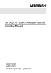
(3) The following shows the operating environment for Web server
module.
Item
Description
Module
QJ71WS96
Compact flash card
64MB or more
Install GX RemoteService-I Version 2 into a compact flash card, and then set it to
the Web server module. (Refer to POINT.)
Note that a compact flash card is compatible with the Web server module with
first five digits of serial number "05112" or later.
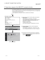
Check the serial number as shown below.
(a)
At SERIAL section in the rating plate, which is situated on the side of
module.
MODEL
MAC ADD.
Serial No. (first 5 digits)
Function version
SERIAL 05112
80M1
IND. CONT. EQ.
MADE IN JAPAN
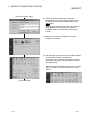
(b)
Using GX Developer or GX Explorer.
The serial number is shown in "Product Information" or "Module's Detailed
Information" screen.
• "Product Information" screen
[Diagnostics] – [System Monitor] – Product Information
• "Module's Detailed Information" screen
[Diagnostics] – [System Monitor] – Module's Detailed Information
For details of operation method, refer to the operating manual of each
software package.
POINT
• For information on the compact flash card (TYPE I storage card that meets
CompactFlashTM specifications) supported by the Web server module, please
contact your local Mitsubishi representative.
• Make sure to use the format function of the Web server module to format a
compact flash card. For details, refer to the Web server module user’s manual.
Note that formatting deletes all files.
When deleting GX RemoteService-I-relevant files only, delete the following folder
and files.
¥SYSTEM (Delete of both folder and files), ADDIN.KEY, STARTUP.KEY,
IJE.CMD, STARTUP.CMD
• When installing GX RemoteService-I into a compact flash card, double-click
"SETUP. EXE" within the CD-ROM and proceed to install according to the
displayed screen.
Specify only the compact flash PC card drive in the destination selection dialog
box, and do not add the folder name after the drive name, as this will result in an
error.
• The Web server module takes 90 seconds to start, if a compact flash card in
which GX RemoteService-I has been installed is set.
2 - 23
2 - 23
2 SYSTEM CONFIGURATION
MELSOFT
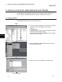
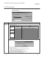
IMPORTANT
A Web server software must be installed to use the Web function.
Make sure that the Web server software is compatible with the operating system
(OS) before installation.
For installation method, refer to Chapter 5.
The following shows the applicable Web server software.
Operating system (OS)
Compatible software
Microsoft Windows 98
Personal Web Server Version 4.0 or later
Microsoft WindowsNT Workstation 4.0
Peer Web Service Version 4.0 or later
R
R
R
R
Microsoft Windows 2000 Professional
R
R
Microsoft Windows XP Professional
R
R
Internet Information Server Version 5.0 or later
• Web server software other than above is inapplicable.
• Windows 98, Windows 2000 and Windows XP must be set up at the time of
installation.
• Set up WindowsNT 4.0 when installing Service Pack 3 or later and Option Pack.
(WindowsNT 4.0 Service Pack 3 or later and Option Pack are available by
downloading them from the Microsoft Corporation home page or by CD-ROM
sending service.)
• Refer to the help function of Windows for the installation method and others of
the server software.
R
R
R
R
R
R
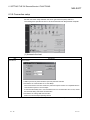
POINT
• Permission of access to folders and files
Use of this product may change the files within the installation destination folder
and sub folders.
Therefore, the user must be granted write access to these folders and files, if
either of the following operating systems is used.
Without this setting, product may not operate correctly.
Microsoft Windows XP Professional
Microsoft Windows 2000 Professional
Microsoft WindowsNT Workstation 4.0
It is recommended to log on as an administrators group user, who is granted to
control the computer, to use this product.
• New functions of Windows XP
Note that this product may not operate correctly when any of the following new
Microsoft Windows XP Professional functions is used, as they are unsupported.
Compatibility mode (The application supported by earlier version of Windows is
run using this mode.)
Fast user switching
Remote desktop
Desktop themes change (Larger font is selected.)
R
R
R
R
R
R
R
R
2 - 24
R
2 - 24
2 SYSTEM CONFIGURATION
MELSOFT
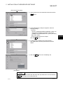
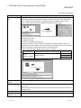
2.3.2 Personal computer
The necessary environment is as follows.
Used Device
Description
When using a personal
computer.
Personal computer where the Web browser has been installed
When using a mobile
1
phone.*
i mode compatible mobile phone
(Microsoft Corporation's Internet Explorer 5.5 or later or Netscape
Communication Corporation's Netscape Communicator 4.5 or later)
R
J-Sky compatible mobile phone
Ezweb compatible mobile phone
*1: This product can be used only in Japan.
y You need to make a contract with a provider.
2 - 25
2 - 25
2 SYSTEM CONFIGURATION
MELSOFT
MEMO
2 - 26
2 - 26
3 FUNCTION LIST
MELSOFT
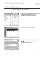
3. FUNCTION LIST
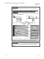
The following provides lists of setting items for the server (personal computer) and for
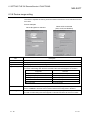
personal computer.
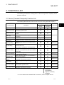
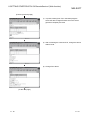
3.1 Server (Personal Computer) Function List
1
The following table lists the functions to be set on the server (personal computer).*
Necessity of setting/operation
Function Name
Description
For Web
For MELSOFT
function
connection
Reference
Operating mode
Sets the automatic or manual operation mode.
Chapter 6
Starts AUTO drive
Starts the continuous monitoring of devices in the
automatic operation mode.
Dial-up execute
Makes dial-up connection to connect with the
Internet.
URL copy
Copies the URL of the server (personal
computer).
Send e-mail
Sends e-mail created with GX RemoteService-I.
Product
information
Displays the version and others of the product.
Security setting
Makes settings related to the security for server
access.
Section 6.3.1
E-mail setting
Makes settings related to e-mail (mail server,
account name, etc.).
Also creates a message for manual operation.
Section 6.3.2
Network setting
Sets the connection type, HTTP port number for
MELSOFT connection and HTTP port number for
Web facility.
Section 6.3.3
PLC type selection
Selects the PLC type of the PLC to be monitored
on the personal computer.
Section 6.3.4
Transfer setup
Selects the path of the PLC to be monitored on
the personal computer.
Section 6.3.5
Device range
setting
Makes settings related to the device to be
monitored on the personal computer.
Section 6.3.6
Tag setting
Makes setting for handling the read devices as
tags.
Section 6.3.7
Auto drive setting
Sets the device to be monitored continuously in
the automatic operation mode.
Section 6.3.8
Dev. disp. setting
Changes the display format of the screen
displayed on the personal computer.
Section 6.3.9
----
----
----
----
Section 6.2
: Necessary
: Unnecessary
: Might be necessary
---- : Irrelevant
*1: For the Web function and MELSOFT connection, refer to Chapter 8 and 9.
3-1
3-1
3
3 FUNCTION LIST
MELSOFT
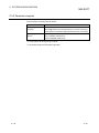
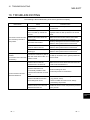
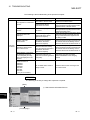
3.2 Personal Computer Side Function List
3.2.1 Monitor functions
The following table lists the functions to be set with the personal computer.
Reference
Description
Tag display
Performs one-shot monitoring of the tag set on the server
Transfer setup
Sets the PLC series, PC side I/F, PLC side I/F and other
(personal computer) side.
3
station.
Device display
Reference
Section
7.2
Section
Device range setting
Sets the device to be monitored.
Device comment search
Makes a device comment search.
Word (Dec)
Displays devices in a word multi-point decimal format.
Word (Hex)
Displays devices in a word multi-point hexadecimal format.
Bit
Displays devices in a bit multi-point format.
Comment Dec
Displays devices in a commented decimal format.
Comment Hex
Displays devices in a commented hexadecimal format.
Comment Bin
Displays devices in a commented binary format.
7.1
Section
7.3
3.2.2 Functions to cut off server (personal computer) line from personal computer
The following table lists the functions that disconnect the server (personal computer)
line from the personal computer.
Reference
Server Side Circuit Settings Time to
Description
Sets the server (personal computer) line disconnection timer.
disconnect the circuit
Server side dial-up disconnect execution
3-2
Disconnects the server (personal computer) line.
Reference
Section
7.4
3-2
4 PRE-OPERATION SETTINGS AND PROCEDURES
MELSOFT
4. PRE-OPERATION SETTINGS AND PROCEDURES
This chapter explains the setting items and procedures necessary for the server
(personal computer) and personal computer.
Personal computer side
(See Section 4.4)
Server (personal computer) side
(See Section 4.1)
Personal computer
Internet
Intranet
4
Mobile phone
4-1
4-1
4 PRE-OPERATION SETTINGS AND PROCEDURES
MELSOFT
4.1 Server (Personal Computer) Setting Procedure
This section explains the procedure for setting the server (personal computer).
Start
Sign-up for provider
Network and Dial-up connection
settings
Installation and setting of browser
Installation of e-mail software
Installation and setting of
GX RemoteService-I
4
Before installing GX RemoteService-I and Web server software,
prepare the server (personal computer) where e-mail and
Internet or other have been confirmed to operate properly.
Refer to the data packed.
Refer to Section 2.3.1 for use of the Web server module.
Security setting
User name and password
Refer to Section 6.3.1.
E-mail setting
Send mail (SMTP) server
Send mail (POP3) server
Account name
Password
E-mail address
Transmission target setting
Refer to Section 6.3.2.
Network setting
Connection type
HTTP port No. for MELSOFT
connection
HTTP port No.for Web facility
Refer to Section 6.3.3.
PLC type selection
PLC type series
PLC type selection
Refer to Section 6.3.4.
Transfer setup
PC side I/F
PLC side I/F
Other station
Network route
Refer to Section 6.3.5.
Device range setting
Device
Points
Program
Target memory
Comment date
Comment type
Refer to Section 6.3.6.
Tag setting
Tag name
Index
Set each device of the tag
Refer to Section 6.3.7.
(To the next page)
4-2
4-2
4 PRE-OPERATION SETTINGS AND PROCEDURES
MELSOFT
(From the previous page)
When manual operation mode is selected
Auto drive setting
Monitor time interval
Watch
Trigger condition
Subject of message
Transmission target setting
Refer to Section 6.3.8.
Dev.disp.setting
Bit device display format
Monitor screen display format
Refer to Section 6.3.9.
Installation of Web server software
Refer to Chapter 5.
End
4-3
4-3
4 PRE-OPERATION SETTINGS AND PROCEDURES
MELSOFT
4.2 INSTALLATION AND UNINSTALLATION
This chapter explains how to install and uninstall the product.
4.2.1 Installation
Install the product according to the following procedure.
(1) Installing Procedure
Install any of GX RemoteService-I in the following procedure.
Updating
New installation
Install the product.
Specify the installation destination.
Register the name and company.
Register the product ID.
Select the installation destination.
Boot the application.
Check whether the product has been
installed properly.
Uninstall the older version.
Refer to the startup
manual of the older
version product.
Install the product.
Specify the installation destination.
Register the name and company.
Register the product ID.
Register the product ID of the older
product.
Select the installation destination.
Boot the application.
Check whether the product has been
installed properly.
Complete
Complete
POINT
If the DLL overwrite confirmation message appears during installation, choose
"Yes" to overwrite the DLLs.
If they are not overwritten, GX Developer may not be run properly.
4-4
4-4
4 PRE-OPERATION SETTINGS AND PROCEDURES
MELSOFT
(2) Installing the product
Before starting installation, confirm the following.
POINT
• Terminate all the other applications running under Microsoft Windows Operating
System before installation.
• When using Windows XP Professional, Windows XP Home Edition, Windows
2000 Professional or Windows NT Workstation 4.0, logon as a user who has the
attributes of an administrator (for computer management).
R
R
R
R
R
R
(The screens of Windows 2000 are used in the explanation.)
R
1) Start Windows Explorer and click the drive in
which the disk has been inserted.
Double-click "Setup.exe".
In the case of Windows 2000 Professional, rightclick [Start] and select [Explorer].
R
R
Double-click here
2) If either of the following messages appears,
perform operation as shown below.
Message
The operating system on this
computer is not admitted as the
environment of this package.
(To the next page)
This package is not in proper
operating environment.
Please install this package after
executing \Update\Axdist.Exe
from CD-ROM.
This package is not in proper
operating environment.
Please install this package after
executing
\Update\50COMUPD.EXE from
CD-ROM.
This package is not in proper
operating environment.
Please install this package after
executing \EnvMEL\Setup.Exe
from CD-ROM.
Reference
(a) in "When a message
appears at start of
installation" of this
section.
(b) in "When a message
appears at start of
installation" of this
section.
(c) in "When a message
appears at start of
installation" of this
section.
(d) in "When a message
appears at start of
installation" of this
section.
3) As the installation destination selection screen
appears, select the installation destination
according to the screen.
4-5
4-5
4 PRE-OPERATION SETTINGS AND PROCEDURES
MELSOFT
(From the previous page)
4) Type the name and company, and click Next> .
As the confirmation dialog box appears, perform
operation in accordance with the message.
5) Type the product ID and click Next> .
The product ID is described on the "License agreement"
included in the product.
6) When the product is to be updated, the screen shown on
the left appears. Type the product ID of the older product
and click Next> .
The product ID is described on the "Software
Registration Card" or "License agreement" included in
the older product.
When the product is to be installed anew, the screen
shown on the left does not appear.
7) Specify the installation Destination Folder.
If the installation Destination Folder displayed is correct,
click Next> .
If you change the destination folder, click Browse and
specify a new drive and folder.
(To the next page)
4-6
4-6
4 PRE-OPERATION SETTINGS AND PROCEDURES
MELSOFT
(From the previous page)
8) This completes installation.
Click OK .
9) Windows must be rebooted if the screen shown on the
left appears.
R
Installation of GX RemoteService-I registers the icon as shown below.
When a message appears at start of installation
In some cases, a message may appear at installation of this product, resulting in
the installation failure.
If this occurs, make sure to close all running applications, and carry out either of
the operations (a) to (d).
(a)
Supported operating system
This product does not support Windows 95.
Reinstall this product into the personal computer in which the supported
operating system has been installed.
R
(b)
Installation of Jaaxdist.exe
Use "Update/Jaaxdist.exe" within this product (CD-ROM) to update
Windows .
Execute Jaaxdist.exe included within this product (CD-ROM). Then, restart
the personal computer and install this product.
The following shows the exe files to be executed for each operating
system.
R
Supported operating system
Microsoft Windows 98
Microsoft Windows 98 Second Edition
Microsoft Windows NT Workstation 4.0
R
R
R
R
R
File name
JaaxDist.exe
R
(JaaxDist.exe is included in "Update" folder, which is within this product, CD-ROM.)
4-7
4-7
4 PRE-OPERATION SETTINGS AND PROCEDURES
(c)
MELSOFT
Installation of 50comupd.exe
This section explains the updating operation of Windows using
"Update\50comupd.exe" on the CD-ROM.
R
1) Click the Yes button to start updating Windows.
2) Accept the agreement on the left screen and click the
Yes button.
3) Click the Yes button to restart the personal computer.
After the personal computer is restarted, start the
installation operation from step (2) 1).
(d)
4-8
Installation of EnvMEL
Execute Setup.exe in the "EnvMEL" folder on this product CD-ROM.
Install GX Developer after executing the "Setup.exe".
After executing the above exe file, install the product again. If this product is
not installed properly at this time, reboot the personal computer.
4-8
4 PRE-OPERATION SETTINGS AND PROCEDURES
MELSOFT
4.2.2 Uninstallation
This section explains deleting this product from the hardware.
Uninstallation of the product
1) Select [Start] – [Settings] – [Control Panel].
Then, select and double-click "Add/Remove
Programs" in the Control Panel.
2) Select "GX RemoteService-I".
Then, click the Add/Remove button.
The screen shown on the left is the one for
Windows 2000 Professional.
The displayed screen varies with the operating
system.
R
When using Windows 2000 Professional perform
the following operation.
R
(a) Click Change/Remove Programs .
(b) Click "GX Configurator-AP".
(c) Click the Change/Remove .
3) Check whether you will remove the software
package or not.
When uninstalling it , click Yes .
Uninstallation starts.
(To the next page)
When not uninstalling it, click No .
This returns to the preceding screen.
* Components indicate the icons and files installed.
4-9
4-9
4 PRE-OPERATION SETTINGS AND PROCEDURES
MELSOFT
(From the previous page)
4) If the left screen has appeared, click the
No To All button.
If you click the Yes or Yes To All button, the
R
shared file of the Windows compatible MELSOFT
software is removed. Therefore, click the No To All
button when removing GX RemoteService-I only.
POINT
If files common to MELSOFT products are
deleted, a MELSOFT product may be
unusable.
5) Click the OK button when the message indicating
the end of removal has appeared.
When the message indicating completion has
appeared, uninstallation is complete.
4 - 10
4 - 10
4 PRE-OPERATION SETTINGS AND PROCEDURES
MELSOFT
4.3 Installing the USB Driver
When Windows 2000 Professional, Windows XP Professional and Windows XP
Home Edition is used, the USB driver must be installed to make CPU USB
communication.
The following is the USB driver installation procedure.
R
R
R
POINT
If the USB driver cannot be installed, check the following setting.
• When Windows 2000 Professional is used
If you have selected "Block-Prevent installation of unsigned files" after [Control
Panel] - [System] - [Hardware] - [Driver Signing], the USB driver may not be
installed.
Choose "Ignore-Install all files, regardless of file signature" or "Warn-Display a
message before installing an unsigned file" for [Driver Signing], and install the
USB driver.
• When Windows XP Professional or Windows XP Home Edition is used
If you have selected "Block-Never install unsigned driver software" after [Control
Panel] - [System] - [Hardware] - [Driver Signing], the USB driver may not be
installed.
Choose "Ignore-Install the software anyway and don't ask for my approval" or
"Warn-Prompt me each time to choose an action" for [Driver Signing], and install
the USB driver.
R
R
R
[1] When Windows 2000 Professional is used
R
The following indicates the procedure for installing the USB driver when using
Windows 2000 Professional.
R
1) The screen shown on the left appears when you connect
the personal computer and QCPU (Q mode) by the USB
cable.
Click the Next> .
(To the next page)
4 - 11
4 - 11
4 PRE-OPERATION SETTINGS AND PROCEDURES
MELSOFT
(From the previous page)
2) Choose "Search for a suitable driver for my device
(recommended)" and click the Next> .
3) Check "Specify a location" and click the Next> .
4) As the screen on the left appears, set the GX Developer
installation destination "Easysocket\USBdrivers" and
click the OK .
The screen shown on the left shows the example of
setting C:\MELSEC\Easysocket\USBdrivers.
If volume MELSOFT products have been installed,
browse the installation destination of the first product.
5) The screen on the left appears to indicate completion of
installation.
Click the Finish> to terminate installation.
(Completion)
4 - 12
4 - 12
4 PRE-OPERATION SETTINGS AND PROCEDURES
MELSOFT
[2] When Windows XP Professional and Windows XP Home Edition is used
R
R
The following indicates the procedure for installing the USB driver when using
Windows XP Professional or Windows XP Home Edition.
R
R
1) The screen shown on the left appears when you connect
the personal computer and QCPU (Q mode) by the USB
cable.
Choose "Install from a list or specific location
[Advanced]" and click the Next> .
2) As the screen on the left appears, choose "Include this
location in the search".
Check "Include this location in the search" and set
"Easysocket\USBDrivers" of the folder where GX
Developer was installed.
After setting, click the Next> .
The screen shown on the left shows the example of
setting C: \MELSEC\Easysocket\USBDrivers.
If volume MELSOFT products have been installed,
browse the installation destination of the first product.
3) As the screen on the left appears, click the
Continue Anyway
REMARK
Though the screen on the left appears during
installation of the USB driver, we have confirmed that
the USB driver operates properly using Windows XP
Professional or Windows XP Home Edition.
(No problem will occur after installation of the USB
driver.)
R
R
Click Continue Anyway to continue the installation of
the USB driver.
(To the next page)
4 - 13
4 - 13
4 PRE-OPERATION SETTINGS AND PROCEDURES
MELSOFT
(From the previous page)
4) The screen on the left appears to indicate completion of
installation.
Click the Finish to terminate installation.
(Completion)
4 - 14
4 - 14
4 PRE-OPERATION SETTINGS AND PROCEDURES
MELSOFT
4.4 Personal Computer Setting Procedure
This section explains the items to be set on the personal computer.
When making access from the personal computer to the server (personal computer),
make a contract to use the Internet with the personal computer.
Start
Make a contract to use
the Internet.
Make a contract according to
the provider.
End
POINT
Refer to Section 2.3.2 for the environment of the usable personal computer.
4 - 15
4 - 15
5 INSTALLATION OF WEB SERVER SOFTWARE
MELSOFT
5. INSTALLATION OF WEB SERVER SOFTWARE
For installation and uninstallation operations of this product (GX RemoteService-I),
refer to "Method of installing the MELSOFT Series" included in the product.
5.1 Windows 98
R
The following indicates how to set up the Web server.
(Start)
1) Set the CD-ROM included with the used server (personal
computer) into the CD-ROM drive and execute
Setup.exe.
Installation starts.
If the above file is not found on the CD-ROM, the installer
is stored in\Windows\Options\Cabs
\Pws in the drive where Windows 98 has been installed.
(Screen shown on the left)
R
5
2) Choose [Programs] - [Microsoft Personal Web Server] [Personal Web Manager].
3) As the screen on the left appears, click [Advanced].
(To the next page)
5-1
5-1
5 INSTALLATION OF WEB SERVER SOFTWARE
MELSOFT
(From the previous page)
4) Choose Home from the Virtual Directories and click the
Add button.
5) As the Add Directory dialog box appears, make the
following settings.
Directory:
Specify "C:\MELSEC\RAS\home\INDEX". (When you
changed the installation destination folder at the
installation of GX RemoteService-I, specify the folder.)
Alias: Enter "Index".
Access: Enable "Read" and "Scripts".
Click the OK button.
6) An alias (index) is added to the virtual directory.
Click [Main] after confirming that the alias has been
added.
7) Click the Start button in the "Publishing" list.
(Completion)
POINT
If you have added the alias with Web issue ON, stop Web issue once and click the
Start button again to turn Web issue ON.
5-2
5-2
5
5 INSTALLATION OF WEB SERVER SOFTWARE
MELSOFT
5.2 Windows NT 4.0
R
The following indicates how to set up the Web server.
(Start)
1) Set the CD-ROM included with the used server (personal
computer) into the CD-ROM drive and execute
setup.exe.
Installation starts.
2) Choose [Programs] - [Windows NT 4.0 Option Pack] [Microsoft Personal Web Server] - [Personal Web
Manager].
3) As the screen on the left appears, click [Advanced].
4) Choose Home from the Virtual Directories and click the
Add button.
(To the next page)
5-3
5-3
5 INSTALLATION OF WEB SERVER SOFTWARE
MELSOFT
(From the previous page)
5) As the Add Directory dialog box appears, make the
following settings.
Directory:
Specify "C:\MELSEC\RAS\home\INDEX". (When you
changed the installation destination folder at the
installation of GX RemoteService-I, specify the folder.)
Alias: Enter "Index".
Access: Enable "Read" and "Scripts".
Click the OK button.
6) An alias (index) is added to the virtual directory.
Click [Main] after confirming that the alias has been
added.
7) Click the Start button in the "Publishing" list.
(Completion)
5-4
5-4
5 INSTALLATION OF WEB SERVER SOFTWARE
MELSOFT
5.3 Windows 2000 (Professional)
R
The following indicates how to set up the Web server.
(Start)
1) Set the CD-ROM included with the used server (personal
computer) into the CD-ROM drive and open
[Add/Remove Programs] from [Control panel].
2) Click [Add/Remove Windows Components].
3) Since the Windows Components Wizard screen starts,
enable [Internet Information Service (IIS)] and click the
Next> button. (Installation starts. Installation ends when
the completion screen appears.)
(To the next page)
5-5
5-5
5 INSTALLATION OF WEB SERVER SOFTWARE
MELSOFT
(From the previous page)
4) Choose [Start] - [Programs] - [Administrative Tool] [Internet Services Manager].
Since [Administrative Tool] in the Start menu is hidden by
default on Windows 2000, display it in the following
operation method.
R
Right-click on the taskbar to display the above menu, and
choose [Properties].
Enable "Display Administrative Tools" in the [Taskbar and
Start Menu Properties].
Internet Service Manager starts.
5) On the screen shown on the left, choose [Default Web
Site] and right-click to choose [New] - [Virtual Directory].
(To the next page)
5-6
5-6
5 INSTALLATION OF WEB SERVER SOFTWARE
MELSOFT
(From the previous page)
6) Virtual Directory Creation Wizard starts.
7) Enter "Index" in [Alias] and click the Next> button.
8) Enter "C:\MELSEC\RAS\Home\Index" in [Directory] and
click the Next> button.
(When you changed the installation destination folder at
the installation of GX RemoteService-I, specify the
folder.)
(To the next page)
5-7
5-7
5 INSTALLATION OF WEB SERVER SOFTWARE
MELSOFT
(From the previous page)
9) Check "Read", "Run scripts (such as ASP)" and click the
Next> button.
10) The virtual directory creation has been completed as the
screen shown on the left appears.
Click the Finish button to finish the wizard.
(Completion)
5-8
5-8
5 INSTALLATION OF WEB SERVER SOFTWARE
MELSOFT
5.4 Windows XP (Professional)
R
The following indicates how to set up the Web server.
(Start)
1) Select [Start] – [Control Panel] – [Add/Remove
Programs] to display "Add/Remove Programs" screen.
Click "Add/Remove Windows Components" icon, which
is situated in the left of the screen.
2) Check [Internet Information Service (IIS)].
When installing IIS with the default setting, click the
Next> button and proceed to step 6.
When setting which sub components will be installed or
not, click the Details button with [Internet Information
Service (IIS)] checked, and proceed to step 3.
3) [Make the settings if necessary.]
Select which sub components will be installed or not by
checking or unchecking the corresponding boxes,
respectively.
After the settings are completed, click the OK button
to return to step 2.
"SMTP Service" and "WWW (World Wide Web)
Service" include respective sub components. When
selecting which sub components will be installed or not,
click the Details button.
When setting "SMTP Service" sub components,
proceed to step 4; "WWW (World Wide Web) Service"
sub components, step 5.
(To the next page)
5-9
5-9
5 INSTALLATION OF WEB SERVER SOFTWARE
MELSOFT
(From the previous page)
4) [Make the settings if necessary.]
Set which sub components will be installed or not by
checking or unchecking the corresponding boxes,
respectively.
For details of sub components, refer to Description
section.
After the settings are made, click the OK button to go
back to step 3.
5) [Make the settings if necessary.]
Set which sub components will be installed or not, by
checking or unchecking the corresponding boxes,
respectively.
For details of sub components, refer to Explanation
section.
After the settings are made, click the OK button to go
back to step 3.
6) Clicking the Next> button at step 2 displays the left
screen and installation of IIS will be started.
7) If the installation of IIS is completed, the left screen
appears. Click the Finish button to close Windows
Components Wizard screen.
(To the next page)
5 - 10
5 - 10
5 INSTALLATION OF WEB SERVER SOFTWARE
MELSOFT
(From the previous page)
8) Choose [Start] - [Programs] - [Administrative Tools] [Internet Information Services].
Since [Administrative Tools] in the Start menu is hidden
by default on Windows XP, display it in the following
operation method.
R
Right-click on the taskbar to display the above menu, and
choose [Properties].
Click the Customize button in the <Start Menu> tab of
the [Taskbar and Start Menu Properties].
Choose "Display on the All Programs menu and Start
menu" in the [Customize Start Menu].
Internet Information Services starts.
9) On the screen shown on the left, choose [Default Web
Site] and right-click to choose [New] - [Virtual Directory].
(To the next page)
5 - 11
5 - 11
5 INSTALLATION OF WEB SERVER SOFTWARE
MELSOFT
(From the previous page)
10) Virtual Directory Creation Wizard starts.
11) Enter "Index" in [Alias] and click the Next> button.
12) Enter "C:\MELSEC\RAS\Home\Index" in [Directory] and
click the Next> button.
(When you changed the installation destination folder at
the installation of GX RemoteService-I, specify the
folder.)
(To the next page)
5 - 12
5 - 12
5 INSTALLATION OF WEB SERVER SOFTWARE
MELSOFT
(From the previous page)
13) Check "Read" and "Run scripts (such as ASP)", and
click the Next> button.
14) The virtual directory creation has been completed as the
screen shown on the left appears.
Click the Finish button to finish the wizard.
(Completion)
5 - 13
5 - 13
6 SETTING THE GX RemoteService-I FUNCTIONS
MELSOFT
6. SETTING THE GX RemoteService-I FUNCTIONS
This chapter explains the function settings to be made on the server (personal
computer).
You may make each setting as desired, but using the Wizard allows you to make
settings easily.
Refer to Chapter 4 for the setting items and procedures.
Starting GX RemoteService-I displays the following screen.
Refer to Section 6.2 and Sections 6.3.1 to 6.3.9 for detailed explanation of the
corresponding setting screens.
6
Select the automatic or manual operation mode and then click the Setting wizard
button to display the Wizard screen.
Whether the setting items must be set or not in the automatic and manual operation
modes is as indicated in the following table.
Setting item
Operation mode
Auto Manual
Security setting
E-mail setting
PLC type selection
Specify target
Device range setting
Tag setting
Dev. Disp. setting
Settings for client authentication. With the settings, the server identifies a client
when the client connects to the server.
Settings for using the GX RemoteService-I mail function.
Not required when using Microsoft Outlook Express or other mail software in
manual operation mode.
Settings for network connection method of the server.
Settings for PLC series and PLC type of the PLC CPU that a client accesses
first.
Settings for connection method between the server and PLC CPU.
Settings for the first device that will be monitored by the client.
Settings for handling devices monitored by the client as tags.
Settings for e-mail transmission triggers and e-mail message.
Required when using auto operation mode.
Settings for screen that appears in the client.
R
Network setting
Auto drive setting
Description
----
: Necessary
6-1
: Might be necessary
---- : Unnecessary.
6-1
6 SETTING THE GX RemoteService-I FUNCTIONS
MELSOFT
6.1 Setting Wizard
The following screen is displayed by clicking the [setting wizard] button on the
operation mode selection screen. Follow the messages to make setting.
The check mark moves
in accordance with
the setting item.
Click here to open
the corresponding
setting screen.
The focus moves to
the item to be set to
indicate which is being set.
6
Click here to
set the next item.
Click here to return to
the previous setting screen.
POINT
Refer to Section 6.3 for the explanation of detailed items to be set with the Setting
Wizard.
6-2
6-2
6 SETTING THE GX RemoteService-I FUNCTIONS
MELSOFT
6.2 Main Screen
This section explains the server URL, dial-up execution, e-mail send and other
functions.
Item
Server URL
Log information
"Clear log" button
Dial-up time
Dial-up
disconnection time
"Starts auto drive"
button
"Dial-up execute"
button
Description
Shows the URL with the IP address.
Shows "---.---.---.---" instead of the IP address if the IP address assigned by the Internet service
provider cannot be acquired.
This product cannot be used when the IP address is not displayed.
Shows error definition in the automatic operation mode.
• Shows the errors and operation of the personal computer.
• Shows the time and date.
• The log can be copied in the selected range.
• The log is up to 100 lines long. If it exceeds 100 lines, the older lines are deleted in due order.
Clears the message in log information.
Shows the elapsed time after dial-up execution.
The time is updated at intervals of five seconds.
"--:--:--" appears if:
• Dial-up is not executed; or
• Dial-up is executed from other than GX RemoteService-I.
If the time has exceeded 9999:59:59 (9999 hours 59 minutes 59 seconds), it returns to 00:00:00.
Appears when the automatic line disconnection system is access time monitoring or dial-up
disconnection timer in the line disconnection setting. ("--:--:--" appears if the setting is not made.)
Counts down to zero.
The time is updated at intervals of five seconds.
For access time monitoring, countdown starts from the preset time every time access is made.
The line is disconnected when the time is zeroed.
Always executes monitoring.
The button name changes to "stop auto drive" during automatic operation, and clicking it
terminates the automatic operation.
Starts dial-up connection with the preset connection name (this button is masked when the dialup connection name is not yet set).
(Continued on next page)
6-3
6-3
6 SETTING THE GX RemoteService-I FUNCTIONS
MELSOFT
(From the previous page)
Item
Description
"URL copy" button
Copies the address displayed in the Server URL.
When sent from the e-mail function of GX RemoteService-I, the address is added to the
mail text automatically.
"Send e-mail" button
Sends e-mail to the preset send destination.
"Product information" button
Displays the version of the product.
"Return to mode selection"
button
Returns to the automatic operation mode/manual operation mode selection screen.
REMARK
The following gives a procedure for sending in the manual operation mode using the
e-mail software such as Microsoft Outlook Express.
R
(Start)
(1) Start the mail software and create a mail text.
(2) Click the "URL copy" button on GX RemoteService-I.
(3) Paste the URL copied from GX RemoteService-I to the
created mail text.
(Completion)
6-4
6-4
6 SETTING THE GX RemoteService-I FUNCTIONS
MELSOFT
6.3 Setting the Server (Personal Computer) Functions
6.3.1 Security setting
When a connection is made to the server, this function identifies the client based on
the user names and passwords registered within the server, in order to prevent an
illegal access. Note that this function is not available while the Web function is used.
Item
Description
Enable
Used to enable/disable the registered name.
User name
User names registered in "User name/Password setting" screen are displayed.
"Edit" button
Used to set the user name and password.
Item
Description
User name
Enter a user name (1 to 20 alphanumeric characters/symbols).
Password
Enter a password (8 to 14 alphanumeric characters/symbols).
Password for
confirmation
Enter the above password for confirmation.
There are following three setting patterns:
1) Both of user name and password are set.
2) Only user name is set.
3) Neither of user name or password is set.
"Delete" button
Used to delete the selected user name and the corresponding password.
POINT
For security setting using the Web server module, refer to the Web server module
user’s manual.
6-5
6-5
6 SETTING THE GX RemoteService-I FUNCTIONS
MELSOFT
6.3.2 E-mail setting
Set as required since the items to be set differ between the automatic and manual
operation modes.
We recommend you to read "Description for Use" or like sent from the provider to
make settings.
Item
Description
Send mail (SMTP)
Specify the server to be used when sending e-mail from GX RemoteService-I.
server
Set the address supplied by the provider.
Number of acceptable characters: 1 to 256 characters
Send mail (POP3)
Enter the server to be used when receiving e-mail.
server
Set the address supplied by the provider.
Number of acceptable characters: 1 to 256 characters
Account name
Specify the account name for POP3 server authentication.
Set the account name supplied by the provider.
Number of acceptable characters: 1 to 255 characters
Password
Specify the password of the account name for POP3 server authentication.
Set the password of the account name supplied by the provider.
Number of acceptable characters: 1 to 255 characters
E-mail address
Specify the returning mail address.
You can set 1 to 255 characters.
Note: Though GX RemoteService-I does not have the function to receive e-mail, set this address
since it is needed when sending e-mail.
Subject of message
Set the subject of e-mail.
Number of acceptable characters: 1 to 256 characters
Note: All the subject may not be displayed depending on the model used.
(Continued on next page)
6-6
6-6
6 SETTING THE GX RemoteService-I FUNCTIONS
MELSOFT
(From the previous page)
Item
Body of message
Description
Enter the text of e-mail. Number of acceptable characters: 0 to 256 characters
Since the URL of the server is added to the character string sent actually, create a message in
consideration of the number of URL characters.
Description
"Transmission target
You can set the send destination in the manual mode only.
setting" button
Item
Description
Trans. e-mail
address
Set the e-mail address of the personal computer.
Set it within the range 1 to 255 characters.
Remarks
Can be used to make a memo of a company name, person's name and like.
Enter them within 256 characters.
Mail
Can be set in the manual operation mode only.
Set whether e-mail will be sent or not.
In the automatic operation mode, the status set for automatic operation setting
appears.
watch 1 to watch 10
Can be set in the automatic operation mode only.
Set whether the system will be monitored or not in the automatic operation
detail setting.
"Copy" button
Used to copy the selected row.
To choose the row, click any of numbers 1 to 20.
You cannot copy the row unless the whole row is selected.
"Paste" button
Used to paste the copied row.
"Delete" button
Used to delete the selected row.
To choose the row, click any of numbers 1 to 20.
You cannot delete the row unless the whole row is selected.
"All clear" button
Used to delete all rows.
Trans. target setting
Mail
: Select whether e-mail will be sent or not.
e-mail specification
Can be set in the manual operation mode only.
during manual drive
Trans. e-mail address
: Shows the e-mail send destination.
Remarks
: You can set the additional information on the e-mail send
destination.
Use mail send of GX
RemoteService-I
6-7
Can be selected in the manual operation mode.
Automatically set in the automatic operation mode.
6-7
6 SETTING THE GX RemoteService-I FUNCTIONS
MELSOFT
6.3.3 Network setting
This section explains the network setting.
Item
Description
"Advanced" button
for "LAN connection"
Item
Description
Acquire IP address
Select this option when an IP address can be
automatically
automatically acquired.
For whether an IP address can be automatically acquired
or not, refer to Section 2. 2.1.
Acquire IP address from a
Select this option when using a UPnP-compatible router
router(UPnP)
or router type DSL modem. An IP address can be
automatically acquired in a system including a router or
other intermediary device.
Use the next IP address
For Intranet or fixed IP, specify the IP address. However,
select "Acquire IP address from a router (UPnP)" for the
internet system including a UPnP-compatible router,
router type DSL modem or other intermediary device,
even if it uses a fixed IP address.
Only numeric characters are applicable for an IP address.
In IP address modification
When the server IP address is changed by line-
by line reconnection, notify
reconnection (due to line-disconnection) in auto drive
you of a mail automatically
mode, GX Remote Service-I will detect the new IP
address to notify the client.
(Continued on next page)
6-8
6-8
6 SETTING THE GX RemoteService-I FUNCTIONS
MELSOFT
(From the previous page)
Item
Description
"Advanced" button
for "Dial-up connection"
Item
Dial-up cnt. name
Description
Select the connection name set in the Dial-up setting.
Up to 16 characters can be displayed.
Redial option
Set the number of times to execute redial for reconnection to
the provider after line disconnection, and the redial execution
intervals. Also set whether to redial (reconnection) in line
disconnecting and notify you of the changed IP address.
Count: Set the number in the range of 0 to 99.
Interval: Set the number in the range of 0 to 999.
Access timer watch
Check this item to disconnect the Dial-up connection if no
access is made to the server (personal computer) for a
certain time.
Hour: Set the number in the range of 0 to 99.
Minutes: Set the number in the range of o to 59.
Note that "0 Hour 0 Minutes" cannot be set.
Dial-up disconnection Check this item to disconnect the dial-up connection after a
timer
certain time has passed.
Hour: Set the number in the range of 0 to 99.
Minutes: Set the number in the range of o to 59.
Note that "0 Hour 0 Minutes" cannot be set.
Enable disconnection Check this item to enable a mobile phone to disconnect the
of Dial-up connection
Dial-up connection of the server (personal computer).
on client side.
Devices other than the mobile phone that disconnected the
connection are not allowed to connect to the server (personal
computer), as the line was disconnected without notice.
HTTP port No.
When "Appoint a port No." is selected, set the port No. in the rage of 1024 to 65535.
for MELSOFT connection
However, when the Web server module is used as operating environment, the port number is
fixed to "8080".
HTTP port No.
When "Appoint a port No." is selected, set the port No. in the rage of 1024 to 65535.
for Web facility
However, when the Web server module is used as operating environment, set the port
number using the Web server module as follows:
Select [Administrative menu] – [System setting].
For details, refer to the Web server module user’s manual.
6-9
6-9
6 SETTING THE GX RemoteService-I FUNCTIONS
MELSOFT
6.3.4 PLC type setting
As the PLC type, set the PLC series and PLC type of the PLC to be accessed first from
the personal computer.
Item
PLC series
PLC type
Description
Set the items when selecting or changing the PLC Series and/or PLC type of the PLC to be accessed first
from the personal computer.
PLC series
ACPU
PLC type
AnN, AnA, AnS, AnSH
AnU, A2AS
⎯
QnACPU
QCPU-Q
FXCPU
A0J2H, A1FX, A1S, A1SJ, A1SH, A1SJH, A1N, A2C,
A2CJ, A2N(S1), A2S, A2SH, A3N, A2A(S1), A3A
A2U(S1), A2AS(S1), A2AS-S30, A2AS-S60, A3U, A4U
Q2A, Q2AS(H), Q2AS1, Q2AS(H)S1, Q3A, Q4A, Q4AR
Qn (H)
Q02(H), Q06H, Q12H, Q12PH, Q25H, Q25PH
Q00J,Q00,Q01
Q00J, Q00, Q01
⎯
QCPU-A
SCPU
Remark
Q02(H)-A, Q06H-A
A171SH
A171SH
A172SH
A172SH
A173UH (S1)
A173UH(S1)
A273UH (S3)
A273UH(S3)
⎯
FX0(S), FX0N, FX1, FXU, FX2C, FX1S, FX1N, FX2N(C)
If you have chosen the PLC Series and/or PLC type other than the one currently set, the following dialog box
appears for confirmation.
Click the "Yes" button to change the following settings and indications.
• Changes the PLC type.
• Changes the connection setup to the PLC CPU direct-coupled path.
• Changes the device range setting to the default value.
• Changes the tag setting to the default value.
• Changes the automatic operation setting to the default value.
Clicking the "No" button does not change the settings.
6 - 10
6 - 10
6 SETTING THE GX RemoteService-I FUNCTIONS
MELSOFT
6.3.5 Connection setup
Set the connection setup between the server (personal computer) and PLC.
This setting also specifies the PLC to be accessed first from the personal computer.
(1) Access to the host
Item
PC side I/F
Description
For Q series
• USB may be set only when the QCPU (Q mode) has been selected.
• Precautions for communication at 115.2/57.6kbps
Fast communication cannot be made if the personal computer used is not compatible with the
communication speed of 115.2/57.6kbps.
If communications delay due to communications tries or a communication error occurs, reduce
the baud rate setting and restart communication.
• Precautions for making USB communication
Refer to the GX Developer Operating Manual.
(Continued on next page)
6 - 11
6 - 11
6 SETTING THE GX RemoteService-I FUNCTIONS
MELSOFT
(From the previous page)
Item
PC side I/F
Description
QnA/A/FX series
• The baud rate that can be selected depends on the PLC Series and PLC type.
• Choose 9.6kbps for the A Series.
• For the QnA Series, the PLC CPU that can communicate at the 38.4kbps speed is the QnACPU
of unction version B or later. Refer to the GX Developer Operating Manual for the way to identify
the module version.
• When using the A6TEL as a converter, refer to the GX Developer Operating Manual.
PLC side I/F
Choose the PLC series of the PLC to be connected with GX RemoteService-I.
Other station
No specification
Specify when the access target is in a multiple PLC system.
Other station (Single network)
It indicates a system which is configured by a single network and a multilevel system, e.g., only
MELSECNET/10 or only Ethernet. (Since Ethernet is regarded as the MELSECNET/10, specify
Single network for an MELSECNET/10 and Ethernet mixed system.)
If a time-out or other error occurs in communications with the PLC CPU, set a longer
communications time check period.
Until the error appears, during execution is displayed in Monitor status.
The longest time until the error appears can be found by the following expression.
(Time specified for communications time check)
3
(Count specified for the number of retries + 1)
For example, when the communications time check is specified as 30 seconds and the number of
retries as 0 times, the resultant time is (30 seconds)
3
(0 + 1) = 90 seconds, and the error
appears after a maximum of 90 seconds have elapsed.
Choose No specification when specifying the own station.
When power-off, hardware reset or the like of the PLC CPU is performed during ladder monitor, it
will take time until a communications error appears.
Network route
Choose the network type, network No., station number and first I/O No. to be accessed.
The setting items depend on the network type that has been set.
Multiple PLC
Specify when the access target is in a multiple PLC system.
Setting
(Continued on next page)
6 - 12
6 - 12
6 SETTING THE GX RemoteService-I FUNCTIONS
MELSOFT
(From the previous page)
Item
Description
Connection channel
You can set the connection target while looking at the Connection channel list.
list
As clicking the [OK] button automatically sets the connection channel on the Connection Setup
screen, settings can be made easily if a complicated system is configured. Set the network
number, station number and others as desired according to the access target.
Click the OK button
Clicking the [OK] button automatically sets the connection path (area enclosed by a circle) on the
Connection setup screen.
About display changing
Convenient use of display selected routes
Specifying the PC side I/F and PLC side I/F and selecting the display selected routes on the
Connection setup screen displays only the paths within the accessible ranges in the other station,
network communication path and mixed network communication path.
A system configuration list of different series can also be displayed.
Request Source
Server
(personal computer)
PLC direct coupled
Server (Personal Computer) Connected PLC
Access Target
Q Series
QCPU (Q mode)
QnA Series
A Series
Useful for changing Other station to Host.
setting
Connection test
Tests whether normal access can be made to the access target PLC CPU set on the Connection
setup screen.
When normal access can be made, the type of the access target PLC CPU appears in the CPU
type display field.
System image
Illustrates the set connection target path.
Line connection
Cannot be set.
(Q/A6TEL, C24)
6 - 13
6 - 13
6 SETTING THE GX RemoteService-I FUNCTIONS
MELSOFT
POINT
Screen setting for MELSECNET/10 and Ethernet combined system (Single
network)
In an MELSECNET/10 and Ethernet mixed system configuration, specify Single
network to access the other station. (Since Ethernet is equivalent to the
MELSECNET/10)
An example of the Connection Setup setting screen is provided for the following
system configuration (Q/QnA only).
Request target (Station 1)
Ethernet
Network No.3
MELSECNET/10
Network No.1
Ethernet
Network No.2
For access to the other station or multilevel system, not only the Connection Setup
but also the routing parameters should be set to enable communications.
POINT
When connecting the PLC to be accessed to the server (personal computer) via
Ethernet, CC-Link or serial communication, refer to GX Developer Operating
Manual.
6 - 14
6 - 14
6 SETTING THE GX RemoteService-I FUNCTIONS
MELSOFT
6.3.6 Device range setting
This section explains the name, points and others of the device to be read first from the
PLC CPU.
Screen examples
When ACPU is selected
(AnU, AnUS, AnUSHCPU)
When Qn(H)CPU is selected
Item
Description
Device
Set the device + device No.
Points
Set any of 1, 16, 32, 64, 128 and 256 points.
Program
Set the program name when monitoring the T/C.
Target memory
When you have set the Qn(H)CPU or QnACPU, make selection from the following memories.
You cannot make setting when the set PLC Series is other than the Qn(H)CPU or QnACPU.
Qn(H)CPU
Comment data
QnACPU
Program memory/Device memory
PLC RAM/Device memory
Memory card (RAM)
IC Card A (RAM)
Memory card (ROM)
IC Card A (ROM)
Standard RAM
IC Card B (RAM)
Standard ROM
IC Card B (ROM)
Set the comment data name to be displayed or searched for by the personal computer.
Fixed to "COMMENT" when the set PLC Series is other than the Qn(H)CPU or QnACPU.
Comment type
Set the comment data name to be displayed or searched for by the personal computer.
You need not make setting when the Qn(H)CPU or QnACPU has been set as the PLC Series.
6 - 15
6 - 15
6 SETTING THE GX RemoteService-I FUNCTIONS
MELSOFT
6.3.7 Tag setting
Setting tags allows you to display different devices you want to read (up to 10 device
types) together on the personal computer.
Tag 10
Tag 3
M105 Rotary pump fault
Tag 2
Thermal fault
Tag 1
M100 Robot controller fault
M101 Robot arm fault
M102 Servo amplifier fault
...........
On personal computer,
change between tags
to check device statuses.
6 - 16
6 - 16
6 SETTING THE GX RemoteService-I FUNCTIONS
Item
MELSOFT
Description
Tag name
Set within 1 to 16 characters.
Index
Set within 0 to 64 characters.
Tag setting
Shows the tag setting status.
"Edit" button
Item
Description
Tag name
Set within 1 to 64 characters.
Index
Set within 0 to 64 characters.
Tag setting
Check this item to enable the tag function.
Device name
Set the device + device No.
Display
Set decimal or hexadecimal.
You cannot set a bit device.
Display name
Set the device name that will be displayed on the personal
computer. Set within 1 to 32 characters.
Program
When you set the T/C as the device name, set the program
name to be referred to.
"Clear" button
Used to clear the selected tag.
"All clear" button
Used to clear all tags.
6 - 17
6 - 17
6 SETTING THE GX RemoteService-I FUNCTIONS
MELSOFT
6.3.8 Automatic operation setting
When performing automatic operation, set an e-mail sending trigger condition, an
e-mail message, etc.
Item
Monitor time interval
Description
Set within the range 30 to 9999 seconds.
Index
Set within 0 to 64 characters.
Watch setting
Shows the monitor setting status.
"Edit" button
(Continued on next page)
6 - 18
6 - 18
6 SETTING THE GX RemoteService-I FUNCTIONS
MELSOFT
(From the previous page)
Item
Description
"Edit" button
Item
Description
Watch
Check this item to perform monitoring.
Index
Set within 1 to 64 characters.
Trigger condition
Set the trigger condition for bit or word device.
The following are the condition enabled examples when the
present value of D33 is 100.
Display
=
<
>
<=
>=
<>
Subject of message
Description
Condition is enabled when the value
is equal to 100.
Condition is enabled when the value
is less than 99.
Condition is enabled when the value
is more than 101.
Condition is enabled when the value
is not more than 100.
Condition is enabled when the value
is not less than 100.
Condition is enabled when the value
is other than 100.
Refer to Section 6.3.2.
Body of message
"Transmission target
setting" button
"Clear" button
Used to delete the selected continuous monitoring setting.
"All clear" button
Used to delete all continuous monitoring settings.
POINT
• If the device set for the trigger condition has already met its condition before a
start of automatic operation, e-mail is sent immediately after automatic operation
is started.
• E-mail is sent when the status of the device set for the trigger condition turns from
OFF to ON.
Note that once e-mail is sent, next e-mail will not be sent until the device status
changes from ON to OFF to ON.
6 - 19
6 - 19
6 SETTING THE GX RemoteService-I FUNCTIONS
MELSOFT
6.3.9 Device display format setting
Set the formats in which the devices read on the personal computer will be displayed.
Item
Bit device display
Description
Choose the bit device display format.
format
Monitor screen display
Choose the combination of the character color and background color.
format
6 - 20
6 - 20
7 ABOUT THE PERSONAL COMPUTER
MELSOFT
7. ABOUT THE PERSONAL COMPUTER
This chapter explains the setting items and display methods on the personal computer.
7.1 List of Personal Computer Setting Items
Making access to the address added to e-mail displays the following screen.
1)
2)
3)
4)
5)
6)
7
7)
8)
9)
10)
11)
12)
13)
14)
15)
16)
17)
7-1
7-1
7 ABOUT THE PERSONAL COMPUTER
No.
MELSOFT
Description
1)
Set the PLC series, PC side I/F, PLC side I/F and other station.
2)
Set the time when the line is disconnected from the personal computer.
3)
Shows the connection form between the server (personal computer) and PLC.
4)
Set the details of the port or board used by the server (personal computer).
5)
6)
7)
Set the details of the module used on the PLC side.
(The screen on the left is an example of a serial communication screen.)
Set within the range 1 to 9999.
Set within the range 0 to 5.
Set the head I/O No., station number and network No. of the module.
The setting items change depending on the module selected for the PLC side I/F.
8)
Specify the PLC No. to be accessed when a multi PLC system is configured.
9)
Choose the display format on the personal computer.
10)
Set the device to be read and its number of points.
11)
Choose the number of read points of the device to be diagnosed.
12)
Choose the program to be diagnosed.
13)
Choose the memory to be accessed.
14)
Choose the comment data to be diagnosed.
15)
Set the keyword for device comment search. (Within 32 characters)
16)
Execution makes access to the PLC.
17)
Choose when monitoring the tag.
7
7-2
7-2
7 ABOUT THE PERSONAL COMPUTER
MELSOFT
7.2 Providing Tag Display
This section explains the tag display screen.
1)
2)
3)
4)
No.
Description
1)
When TC is displayed, (Contact), (Coil), (Set value) or (Present value) is added to its display name.
2)
Select the tag you want to display from the tag list.
Monitors a list of devices chosen by tag selection.
3)
Note that the statuses of the devices read to the personal computer are those when start is clicked.
Note: The read devices do not vary in real time.
4)
7-3
Moves to the device monitor page.
7-3
7 ABOUT THE PERSONAL COMPUTER
MELSOFT
7.3 Monitoring the Devices
This section explains the device display formats.
The following gives the examples of the Web browser and personal computer displays
provided when the remote device monitor function is used.
(a) Word multi-point decimal
(b) Word multi-point hexadecimal
(c) Bit multi-point
7-4
7-4
7 ABOUT THE PERSONAL COMPUTER
MELSOFT
(d) Commented decimal
(e) Commented hexadecimal
(f) Commented binary
7-5
7-5
7 ABOUT THE PERSONAL COMPUTER
MELSOFT
7.4 Setting the Server (Personal Computer) Line Connection
This section explains the server (personal computer) side line disconnection timer
setting and line disconnection on the personal computer.
Item
Description
Server Side Circuit Settings
Set the time until the line is disconnected.
Time to disconnect the
When making this setting, preset "Enable disconnection of dial-up connection on client side"
circuit
on the dial-up setting screen.
Server side dial-up
Disconnects the dial-up connection.
disconnect execution
7-6
7-6
8 GETTING STARTED WITH GX RemoteService-I (Web function)
MELSOFT
8. GETTING STARTED WITH GX RemoteService-I (Web function)
This chapter describes the setting of GX RemoteService-I functions on the server
(personal computer) under the conditions presented in Section 8.1 and the
confirmation of tag displays and device displays on the personal computer.
Section 8.1 explains the setting of GX RemoteService-I.
Section 8.2 explains the varying of the monitor devices and the arrival of e-mail.
Section 8.3 explains the operation procedure of looking at the server (personal
computer) after the arrival of e-mail.
8.1 Setting GX RemoteService-I to the Server (Personal Computer)
Outline of setting example
(1) Setting of e-mail sending conditions
When the trigger condition is enabled, make settings to send e-mail to two
persons.
• When M1000 turns on, Mr. A is informed of a "robot" fault.
• When M1001 turns on, Mr. B is informed of a "press" fault.
(2) Setting of devices read by the personal computer
• Make tag settings (three tags) for confirming the system status.
• Make setting to read the annunciator (F) first for checking the fault status of the
system.
Conditions
Setting item
Setting
Operating mode
Automatic operation mode
Security setting
Must not be set.
Send mail (SMTP) server
E-mail
setting
Receive mail (POP3) server
Account name
Refer to "Description for Use" or like sent from the provider and make settings.
Password
E-mail address
Network setting
Connection type: LAN connection
In IP address modification by line reconnection, notify of a mail automatically:
Unchecked.
PLC type
QCPU (Q mode), Qn (H)CPU
Transfer setup
PLC direct connection
Device
Device
range
setting
F0
Note: Set the F0 comment on GX Developer and write it to the PLC CPU in
advance.
Points
16 points
Program
MAIN
Target memory
Program memory/device memory
Comment data
COMMENT
(Continued on next page)
8-1
8-1
8
8 GETTING STARTED WITH GX RemoteService-I (Web function)
MELSOFT
(From the previous page)
Setting item
Setting
Tag name
Device name
Display format
Display name
M100
⎯
Robot controller fault
M101
⎯
Robot arm fault
M102
⎯
Servo amplifier fault
X100
⎯
Thermal fault
D100
Decimal
Coolant pressure low
X130
⎯
Die fault
M105
⎯
Rotary pump fault
Robot
(Tag 1)
Tag setting
Press
(Tag 2)
Transfer
(Tag 3)
1
2
⎯
Stocker cylinder fault
Decimal
Transfer motor speed
Index
Plant A Line A
Trigger condition
M1000 turns on
Subject of message
Fault occurred in robot.
Body of message
Auto drive setting
X150
D110
A fault occurred in the line A robot.
Check the system.
Trans. e-mail address
Mr. A aaa@***.co.jp
Index
Plant A Line B
Trigger condition
M1001 turns on
Subject of message
Fault occurred in press
Body of message
Trans.e-mail address
Dev. disp. setting
A fault occurred in the line B press.
Check the system.
Mr. B bbb@***.ne.jp
Character display (ON:
OFF:
)
Conceptual diagram of system
8
Robot fault
Internet
Press fault
8-2
Robot fault
Line A
Mr. A
Mr. B
When M1000 turns on,
e-mail is sent to Mr. A.
M1000
M1000
When M1001 turns on,
e-mail is sent to Mr. B.
M1001
M1001
Press fault
Line B
8-2
8 GETTING STARTED WITH GX RemoteService-I (Web function)
MELSOFT
(Start)
1) Start GX RemoteService-I.
2) Choose the Auto run mode and click the
Setting wizard button.
3) This screen is for the security setting to prevent an
illegal access.
If this setting is not necessary, click the Next>
button.
4) Set e-mail to notify the personal computer.
Click the E-mail setting button.
(To the next page)
8-3
8-3
8 GETTING STARTED WITH GX RemoteService-I (Web function)
MELSOFT
(From the previous page)
5) Set the e-mail common information.
Set the following data of the provider with whom you
have contracted.
• Send mail (STMP) server
• Account name
• Receive mail (POP3) server • Password
• E-mail address
After the setting is finished, click the Setting completion
button.
REMARK
For the settings, refer to "Description for Use" or like sent
from the provider.
6) Set the details of Network.
Click the Network setting button.
7) Set Connection type/HTTP port No. for MELSOFT
connection/ HTTP port No. for Web facility.
Select "LAN connection" this time, and click the
Setting completion button.
The operations after the Advanced button is clicked
are explained on the next page.
(To the next page)
8-4
8-4
8 GETTING STARTED WITH GX RemoteService-I (Web function)
MELSOFT
(From the previous page)
• In the case where LAN connection is selected
and the Advanced button is clicked.
Select an IP acquisition method.
After the settings are completed, click the
Setting completion button.
This returns to "Network setting" screen.
• In the case where Dial-up connection is
selected and the Advanced button is
clicked.
Set the dial-up connection target and line
disconnection method.
After the settings are completed, click the
Setting completion button.
This returns to "Network setting" screen.
REMARK
Be sure to make the dial-up settings before making
the advanced dial-up settings.
Without the settings, the following screen appears and
the dial-up setting screen cannot be opened.
8) Connect the server (personal computer) and PLC
CPU.
Prepare a program that can turn on M1000 and
M1001 beforehand for the PLC CPU.
9) Set the PLC series and PLC type of the PLC CPU to
be accessed first by the personal computer.
Click the PLC type selection button.
(To the next page)
8-5
8-5
8 GETTING STARTED WITH GX RemoteService-I (Web function)
MELSOFT
(From the previous page)
10) Choose the PLC series and PLC type of the PLC CPU
to be connected to the server (personal computer).
After the setting is finished, click the
Setting completion button.
11) Set the connection path from the server (personal
computer) to the PLC CPU.
Click the Specify target button.
12) Set the path for connection of the server (personal
computer) and PLC CPU.
After the setting is finished, click the Connection test
button to start a communication test.
When normal communication is made, the CPU type
appears in the CPU Type display field.
After the setting is finished, click the OK button.
13) Set the device, number of points, and program name to
be read first when the PLC CPU is accessed by the
personal computer.
Click the Device range setting button.
(To the next page)
8-6
8-6
8 GETTING STARTED WITH GX RemoteService-I (Web function)
MELSOFT
(From the previous page)
14) Set the device name (F0), number of points (16
points), and program name (MAIN).
Refer to Section 6.3.6 for detailed explanation of
the target memory and comment.
After the setting is finished, click the
Setting completion button.
15) Make setting to read different types of devices
(up to 10 types) together to the personal
computer.
Click the Tag setting button.
16) Choose No. 1 and click the Edit button.
Out of the three tags to be set, Tag 1 will only be
explained here.
17) Set the tag name, device names and display
names.
After the setting is finished, click the
Setting completion button.
(Set Tag 2 and Tag 3 in the same procedure.)
(To the next page)
8-7
8-7
8 GETTING STARTED WITH GX RemoteService-I (Web function)
MELSOFT
(From the previous page)
18) When editing Tag 2 or Tag 3, move the cursor to No. 2
or 3 and click the Edit button.
To end, click the Close button.
19) Make setting to monitor the system automatically.
Click the Auto drive setting button.
20) Choose No. 1 and click the Edit button.
21) Set the Watch, Index, Trigger condition (M1000),
Subject of message, Body of message.
Click the Transmission target setting button.
(To the next page)
8-8
8-8
8 GETTING STARTED WITH GX RemoteService-I (Web function)
MELSOFT
(From the previous page)
22) Set the Trans. e-mail address.
Setting Mr.A at watch 1.
After the setting is finished, click the
Setting completion button.
23) Click the Setting completion button.
24) Move the cursor to No. 2 and click the Edit button.
25) Set the Watch, Index, Trigger condition (M1001),
Subject of message, Body of message.
Enable 2 under "Mail".
Click the Transmission target setting button.
(To the next page)
8-9
8-9
8 GETTING STARTED WITH GX RemoteService-I (Web function)
MELSOFT
(From the previous page)
26) You can check the combinations for sending e-mail on
the left screen.
When the check is finished, click the
Setting completion button.
27) Set the display format of the screen to be displayed on
the personal computer.
Click the Dev. disp. setting button.
28) Choose "Character display (ON:
OFF:
)" and click
the Setting completion button.
(To the next page)
8 - 10
8 - 10
8 GETTING STARTED WITH GX RemoteService-I (Web function)
MELSOFT
(From the previous page)
29) Start the Web server software and click the Start
button.
Refer to Chapter 5 for starting the Web server software.
30) Click the Start auto drive button.
(Completion)
8 - 11
8 - 11
8 GETTING STARTED WITH GX RemoteService-I (Web function)
MELSOFT
8.2 Varying of Monitor Devices and Arrival of E-mail
Using the device test function of GX Developer, vary the monitor devices set on GX
RemoteService-I and make sure that e-mail arrives.
Preinstall GX Developer into the server (personal computer).
(Start)
1) Start GX Developer installed in the server (personal
computer).
Read the PLC program from [Online] - [Read from
PLC].
For program reading operation, refer to the GX
Developer Operating Manual.
2) After stating program monitoring from GX Developer,
choose [Online] - [Debug] - [Device test] and set
M1000 for "ON" and M1001 for "ON" on the left
screen.
When M1000 is turned "ON", e-mail is sent to Mr. A.
When M1001 is turned "ON", e-mail is sent to Mr. B.
For GX Developer operation, refer to the GX
Developer Operating Manual.
3) E-mail is sent from GX RemoteService-I and notifies
the personal computers.
e-mail is sent to Mr. A
when M1000 turns on.
Mr. A
GX RemoteService-I
e-mail is sent to Mr. B
when M1001 turns on.
Mr. B
(Completion)
8 - 12
8 - 12
8 GETTING STARTED WITH GX RemoteService-I (Web function)
MELSOFT
8.3 Receiving E-mail and Looking at Devices on Personal Computer
This section explains how to perform operation to check the e-mail sent from GX
RemoteService-I and check the tag and device displays.
8.3.1 Until looking at tag
Outline of operation
The following operation example explains how to choose Tag 2 (press) and
check the operating status of the system after receipt of e-mail.
(Start)
1) The e-mail sent from GX RemoteService-I is received.
Check the received e-mail.
After confirming the message, click the URL of "Tag
reference".
2) The left screen appears.
Choose [Tag select].
(To the next page)
8 - 13
8 - 13
8 GETTING STARTED WITH GX RemoteService-I (Web function)
MELSOFT
(From the previous page)
3) As a list of tag names appears, choose "Press".
4) Choose Start .
5) The devices set for the press are read.
(Completion)
8 - 14
8 - 14
8 GETTING STARTED WITH GX RemoteService-I (Web function)
MELSOFT
8.3.2 Until looking at devices
Outline of operation
Following the operation in Section 8.3.1, monitor the device (F) using "Device
reference" to check the details of the faulty status. The following operation
example explains how to change the monitored device to the data register (D).
(Start)
1) The e-mail sent from GX RemoteService-I is received.
Check the received e-mail.
After confirming the message, click the URL of
"Device reference".
2) Scroll the screen down.
3) Choose Start .
(To the next page)
8 - 15
8 - 15
8 GETTING STARTED WITH GX RemoteService-I (Web function)
MELSOFT
(From the previous page)
4) 16 points, starting from F0, in the MAIN program
where the device range has been set on the server
(personal computer) are read.
5) After confirming the contents of F0, change the device
data to D100.
6) Change F0 to D100.
(To the next page)
8 - 16
8 - 16
8 GETTING STARTED WITH GX RemoteService-I (Web function)
MELSOFT
(From the previous page)
7) Choose Start .
8) The D100 value can be read.
(Completion)
8 - 17
8 - 17
9 MELSOFT CONNECTION FUNCTION
MELSOFT
9. MELSOFT CONNECTION FUNCTION
The MELSOFT connection function is to access the PLC CPU via Internet/Intranet
using a software package (MELSOFT) installed in the client side.
9.1 Using the MELSOFT connection function
9.1.1 When the server is personal computer/PC CPU module
The following explains the procedure to access the PLC CPU through a personal
computer/PC CPU module.
GX Explorer Version 2
Internet
Intranet
GX Explorer Version 2
Client (personal computer in which
GX Explorer Version 2 is installed)
9
9-1
GX RemoteService-I Version 2
Server (personal computer in which
GX RemoteService-I Version 2 is installed)
9-1
9 MELSOFT CONNECTION FUNCTION
MELSOFT
• Remote access operation procedure
(Server side)
GX RemoteService-I
: Indicates the operation
by the operator.
Select the operation mode
(auto/manual).
: Indicates the automatic
operation by the server.
Set the following items in the main screen
of GX RemoteService-I.* 1
Security setting
E-mail setting
Network setting
PLC type selection
Specify target
Auto drive setting
Refer to
Chapter 6.
For details, refer
to Section 6.3.
Execute dial-up to connect to the provider.
(Not required for continuous connection.)
Confirm the IP address assigned by the
provider at the server URL display section
in the main screen.
(Client side)
GX Explorer
Confirm the notified IP address and port
number.
Refer to Section 9.2 (1).
Connect to the server based on the IP
address and port number.
Refer to Section 9.2 (2) to (5).
Notification
*2
Notify the client of the assigned IP address
and the HTTP port No. for MELSOFT
connection set in the Network setting.* 3
Request to connect
to the server
Client authentication.
Connection permitted.
Make the settings in order that the network
configuration including the target station
will be analyzed.
Refer to Section 9.2 (6).
Set the connection route to the target PLC
CPU.
Refer to Section 9.2 (7).
Connect to the target PLC CPU.
Execute each function.
Refer to Section 9.2 (8).
Terminate the communication with the
target PLC CPU.
Refer to Section 9.2 (9).
Completed
9-2
Connection
Connection to the target PLC CPU.
Remote access
Communication with the target PLC CPU.
Communication
termination
9
Communication with
the target PLC CPU completed.
Completed
9-2
9 MELSOFT CONNECTION FUNCTION
MELSOFT
*1: The following items must be set using GX RemoteService-I installed in the server, in order to access the
PLC CPU from the client using the MELSOFT connection function.
Setting item
Operation mode
Auto
Description
Manual
Settings for client authentication. With the settings, the server identifies a client
Security setting
when the client connects to the server.
Settings for using the GX RemoteService-I mail function.
Not required when using Microsoft Outlook Express or other mail software in
E-mail setting
R
manual operation mode.
Network setting
Settings for network connection method of the server.
PLC type selection
Settings for PLC series and PLC type of the PLC CPU that a client access first.
Specify target
Settings for connection method between the server and PLC CPU.
Auto drive setting
----
Settings for e-mail transmission triggers and e-mail message.
Required when using auto operation mode.
: Necessary
: Might be necessary
---- : Unnecessary.
*2: Manual mode: The operations are performed by the operator. (Refer to Section 6.2)
Auto drive mode: The operations are automatically performed when trigger conditions (set in the auto drive
setting) are met.
*3: For auto drive mode, make the e-mail setting and auto drive setting. With these settings, the mail including
the server IP address and HTTP port No. for MELSOFT connection will be automatically sent to the client
when trigger conditions (set in the auto drive setting) are met.
9-3
9-3
9 MELSOFT CONNECTION FUNCTION
MELSOFT
9.1.2 When the server is Web server module
The following explains the procedure to access the PLC CPU through the Web server
module. In the explanation, GX Explorer Version 2 is taken as an example.
When using the Web server module as the server, set a compact flash card in which
GX RemoteService-I has been installed into the Web server module.
• Remote access operation procedure
(Server side)
Web server module
: Indicates the operation
by the operator.
Set the following items in the
standard screen for the Web
server module setting/monitoring,
as necessary.
System setting
Dial-up setting
E-mail setting
Address notification setting
Account setting*1
: Indicates the automatic
operation by the server.
Power the PLC OFF and ON.
Or reset the PLC CPU.
(Client side)
GX Explorer
Confirm the notified IP address and
port number.
Refer to Section 9.2 (1).
Connect to the server based on the
IP address and port number.
Refer to Section 9.2 (2) to (5).
When using the Web server
module in the environment for
automatic acquisition of IP
address, dial-up setting, e-mail
setting and address notification
setting are required.
For details, refer to the Web
server module users manual.
Notification
Notify the client of the server IP
address and the port number.*2
Request to connect
to the server
If the e-mail setting and address
notification setting are made,
the server IP address and port
number will be automatically
sent to the client.
Client authentication.
Connection permitted.
Make the settings in order that the
network configuration including the
target station will be analyzed.
Refer to Section 9.2 (6).
Set the connection route to the
target PLC CPU.
Refer to Section 9.2 (7).
Connect to the target PLC CPU.
Execute each function.
Refer to Section 9.2 (8).
Terminate the communication with
the target PLC CPU.
Refer to Section 9.2 (9).
Completed
Connection
Connection
to the target PLC CPU.
Remote access
Communication
with the target PLC CPU.
Communication
termination
Communication with
the target PLC CPU completed.
Completed
*1: Make the account setting as necessary.
*2: If the e-mail transmission is not available, confirm the Network connection of the server module by checking
the buffer memory using GX Developer. For details, refer to the GX Developer Version 8 operating manual.
9-4
9-4
9 MELSOFT CONNECTION FUNCTION
MELSOFT
9.2 Application example of the MELSOFT connection function
The following explains how to connect to the server based on the e-mail sent from the
server; to make a remote access to the PLC CPU through the server; to complete the
communication with the PLC CPU.
In the explanation, GX Explorer Version 2 is taken as an example.
(Start)
(Example of received-mail)
(1) This screen is for the security setting to prevent an
illegal access.
If this setting is not necessary, click button.
The e-mail sent from the server provides the server
information (IP address and HTTP port No. for
MELSOFT connection).
IP address follows "http:// ".
(For the left message, it corresponds to "0.0.0.0")
(2) Start GX Explorer Version 2 from the personal
computer (client).
Select [Object] – [MELSOFT connection] from the
menu to display "MELSOFT connection" dialog box.
(3) Specify the connection target server by setting the
host name or the IP address and port number, and
click the Connection button.
(To the next page)
9-5
9-5
9 MELSOFT CONNECTION FUNCTION
MELSOFT
(From the previous page)
(4) If Security setting has been made using GX
RemtoeService-I, the left message appears. Enter
the preset user name and password and click the
OK button.
When the Web server module is used as the server,
"Enter Network Password" dialog box appears.
For details, refer to the Web server module user’s
manual.
(5) When the connection is completed, the screen
changes as shown left.
(6) Set information from the server to the station targeted
for an analysis of network configuration.
For details, refer to "Network Configuration Analysis
Specification" provided in the GX Explorer Version 2
operating manual.
When the server is Web server module, set “Q Series
Bus” in PC side I/F, and "Web Server Unit” in PLC
side I/F.
(To the next page)
9-6
9-6
9 MELSOFT CONNECTION FUNCTION
MELSOFT
(From the previous page)
(7) Set information from the server to the station targeted
for an analysis of network configuration.
For details, refer to "CONNECTION TARGET
SPECIFICATION" provided in the GX Explorer
Version 2 operating manual.
When the server is Web server module, items set in
PC side I/F and PLC side I/F are the same with the
items described in (6).
(8) A remote access can be made to the target PLC CPU
in order to execute each GX Explorer Version 2
function.
(9) When terminating the remote access communication
with the PLC CPU, click the Disconnection button to
disconnect the connection to the server.
(Completion)
9-7
9-7
10 TROUBLESHOOTING
MELSOFT
10. TROUBLESHOOTING
The following is the troubleshooting of the server (personal computer).
Phenomenon
Check
Corrective Action
Check that the dial-up network has
Make sure that the dial-up network exists in the
been installed.
Control Panel.
Check that "Dial-up connection
Make sure that the connection target has been
name" of the dial-up network has
registered within the dial-up network in the Control
been set.
Panel.
Connection cannot be made
Check that the modem driver has
Make sure that the modem used for the modem
from the dial-up network to
been installed.
properties in the Control Panel is displayed.
the provider.
Dial-up connection is
instable.
(Connection cannot be made
sometimes.)
The modem does not dial.
Check by clicking the icon of the connection target
within the dial-up network in the Control Panel.
The modem dials but connection
Check by clicking the icon of the connection target
cannot be made to the host.
within the dial-up network in the Control Panel.
The line was connected but you
Check by clicking the icon of the connection target
cannot log in.
within the dial-up network in the Control Panel.
Connection is made from a place of
weak radio wave with a mobile, or a
local line is used.
For dial-up connection, enter ", (pause)" before the
phone number.
Check that the e-mail of GX
Make sure that correct values have been set to the
RemoteService-I has been set.
e-mail of GX RemoteService-I.
• Check that mail can be set to the
specified destination from
commercially available e-mail.
e-mail cannot be sent from
GX RemoteService-I.
• Check that the software can send
Check the settings for error.
Contact the provider for confirmation.
mail.
• Check that the set character string is correct
Check that the SMTP and POP3
server settings are correct.
(e.g. periods, colons).
• Check the SMTP and POP3 server settings
presented by the provider.
Check that the account name and
Confirm the account name and password presented
password have been set.
by the provider.
10
10 - 1
10 - 1
10 TROUBLESHOOTING
MELSOFT
The following is the troubleshooting of the personal computer.
Phenomenon
Error appears in commented
monitor.
Check that the device
comments are correct.
Error appears in T/C device
monitor.
Check that the program name
is correct.
Tag names cannot be
displayed.
Check that tag setting has
been made to the server
(personal computer).
The line cannot be
disconnected.
Common
to clients
Check
Check that device comments
are written to the PLC CPU.
The dial-up disconnection
timer cannot be set.
When devices or comments
are displayed, a time-out
occurs frequently and they
cannot be displayed on the
browser.
Communication cannot be
made with the PLC.
01802001
01802002
01802005
010*4030
010*4031
010*4032
(*: Any of 0 to F enters.)
Check that disconnection from
the personal computer is
enabled on the server
(personal computer).
Check that dial-up
disconnection timer setting
from the personal computer is
enabled on the server
(personal computer).
Corrective Action
Using GX Developer, check that device
comments have been written.
Display the device setting screen of the
server (personal computer) and check the
registered device comment names.
Display the device setting screen of the
server (personal computer) and check the
registered program name.
Display the tag setting screen of the server
(personal computer) and make sure that
the tag names have been registered and
the setting is valid.
Display the dial-up setting screen of the
server (personal computer) and make sure
that "Server Side Circuit Settings Time to
disconnect the circuit" has been turned on.
Display the dial-up setting screen of the
server (personal computer) and make sure
that "Server Side Circuit Settings Time to
disconnect the circuit" has been turned on.
Check the script time-out
period on the server (personal
computer).
Change the script time-out period.
Refer to REMARKS for the changing
method.
An unusable device name or
range is used.
Check the device name and range in the
PLC CPU manual.
REMARK
The following is the way to change the script time-out period.
(Start)
1) Start Internet Information Service.
10
(To next page)
10 - 2
10 - 2
10 TROUBLESHOOTING
MELSOFT
(From previous page)
2) Right-click the virtual directory [Index] of GX
RemoteService-I and choose [Properties].
3) Click the "Configuration" button in the <Virtual
Directory> tab.
4) Change [ASP Script timeout] to about 200 seconds in
the <App Options> tab and click the OK button.
(Completion)
10 - 3
10 - 3
APPENDICES
MELSOFT
APPENDICES
App
APPENDIX 1 RESTRICTIONS
The following table indicates the restrictions on use of GX RemoteService-I.
Item
Monitor
Restrictions
The monitor display or like (inquiry to the personal computer) is slow or the monitor display
results in a time-out.
Setting check
Checks on set values, such as device names and ranges, are made by the server (personal
Search
Comment search may not be executed using a mobile phone, depending on the
line condition.
Web server module
Web server module with first five digits of serial number “05112” or later is
applicable to this software package.
MELSOFT connection
function
When performing the MELSOFT connection, install Internet Explorer 6.0 or later
into the operating environment of server. (Installed in Windows XP by default.)
Connection set up
Only global IP is applicable for a dial-up router.
(IP masquerade is unsupported.)
Web function
The Web function can be executed by the Windows personal computer or PC
CPU module.
In the case of the Web server module, use functions included in the module as
standard.
Performance
(communication speed)
Update operation for the client may be delayed or communication time out error
may occur during remote access, depending on the line condition.
Server connection
It is required to notify the client of the server IP address and HTTP port number for
each dial-up connection.
LAN connection
When acquiring an IP address from DHCP server, note that the server changes
the IP address regularly. Because of this character, if "Acquire IP address
automatically" is set for LAN connection, this setting will not be supported.
Number of connected
servers
One client cannot connect to multiple servers (personal computers)
simultaneously.
Max number of
connections
The number of allowable connections (clients) varies with the execution
environment. Therefore, if many clients are connecting to the server, an error
occurs and the corresponding dialog box appears.
In this case, disconnect the unnecessary connections or execute re-connection
after a certain time has passed.
Number of objects that
can be monitored
Up to 20 objects can be monitored through a connection to the server (personal
computer).
(One client is allowed to request to connect to more than two objects. In object
unit.)
Installation
Installation of this software package into a personal computer/PC CPU module is
allowed to the user who has logged on as an administrators group only.
computer).
App - 1
R
App - 1
APPENDICES
Item
MELSOFT
Restrictions
Modem connection
When performing the MELSOFT connection, note that connection route via
modem within the connection between the server and PLC system is not
supported. (e.g., via Q6TEL or QJ71CMO)
Ethernet board/card
This software package may not work correctly in the personal computer that uses
multiple Ethernet boards/cards.
IP address
Multiple IP addresses cannot be assigned to the personal computer/PC CPU
module including this software package.
Line connection
The URL of the server (personal computer) must be mailed to the personal
computer every time the server (personal computer) dials up.
App
The IP address assigned by the provider that the server (personal computer) dials
up must be the global IP address.
The number of personal computers connectable to PWS simultaneously is up to
10.
If there are more than 10, HTTP error 403 is displayed on the browser.
When connection is made from the browser designed for the server (personal
computer), PWS counts the number of connected personal computers as 2.
A response from the server (personal computer) may be slow depending on the
line conditions and like of the provider and between the relayed Internet servers.
App - 2
App - 2
INDEX
Ind
[A]
Automatic operation mode
About automatic operation ......................... 1- 5
Automatic operation setting .......................... 6-18
[C]
Connection setup .......................................... 6-11
[D]
Device/comment display examples ............... 7- 4
Device display format setting........................ 6-20
Device range setting ..................................... 6-15
Displaying tags ............................................... 7- 3
[S]
Setting and procedure
Personal computer .....................................4-15
Server (personal computer) ........................4- 2
Setting GX RemoteService-I to server
(personal computer)....................................8- 1
System device list
Connection from interface board ................2- 7
Connection from serial/USB port................2- 2
Setting Wizard .............................................6- 2
Types of usable modules............................2- 9
[T]
Tag setting .....................................................6-16
[E]
E-mail setting.................................................. 6- 6
[F]
Function list
Personal computer ..................................... 3- 2
Server (personal computer) ....................... 3- 1
[U]
Until looking at devices ..................................8-15
Until looking at tags........................................8-13
[W]
Web server installation
Windows 2000...........................................5- 5
Windows 98 ...............................................5- 1
Windows NT 4.0 ........................................5- 3
Windows XP ..............................................5- 9
R
[M]
Main screen .................................................... 6- 3
Manual operation mode
About manual operation ............................. 1- 5
R
R
R
[N]
Network setting............................................... 6- 8
[O]
Operating environment
Personal computer .................................... 2-25
Server (personal computer) ...................... 2-22
[P]
Personal computer
Line connection setting....................... 3- 2, 7- 6
PLC type setting ............................................ 6-10
Index - 1
Index - 1
MEMO
Index - 2
Ind
Index - 2
Microsoft, Windows, Windows NT are registered trademarks of Microsoft Corporation in the United States and other countries.
Adobe and Acrobat are registered trademarks of Adobe Systems Incorporation.
Pentium and Celeron are trademarks of Intel Corporation in the United States and other countries.
Ethernet is a trademark of Xerox Co., Ltd. in the United States.
Other company names and product names used in this document are trademarks or registered trademarks of respective owners.
SPREAD
Copyright (C) 1999 Farpoint Technologies, Inc.
SH (NA) 080465ENG-F