1
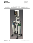
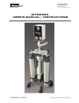
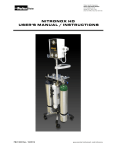
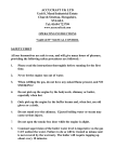
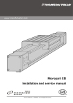
NITRONOX SCAVENGER SYSTEM
USER’S MANUAL / INSTRUCTIONS
Examination
All components should be removed from their respective shipping containers and examined. Any
omissions and/or damage should be reported to the Porter dealer, immediately.
User Responsibility
T h e Nitronox® Scavenger System is designed for use with the Nitronox Inhalation Analgesia
System (Refer to Instructions 10115900), and to perform in accordance with specifications herein
when installed, operated and maintained as instructed in this manual. It should be carefully read
and understood prior to operation and use of the scavenger system.
Warnings
Use Scavenging Monitor for N2O in the patient treatment area to insure that controls are
effective in achieving low levels of ppm (parts per million) exposure. Contact Porter or
Authorized Distributor for details on monitors and testing.
The Nitronox Scavenger System is intended to be used by medical personnel trained in its
use and the use of nitrous oxide and oxygen for medical applications.
An EXPLOSION hazard exists when flammable agents are exhausted into the vacuum system
(Page 7).
The Nitronox Scavenger interface is supplied with a removable flow resistor. This foam
resistor must be REPLACED every six months to help prevent the possibility of increased
resistance due to particle entrapment (Page 8).
Medical workers are exposed to N2O during administration of N2O/O2 conscious sedation
analgesia. NIOSH has recommended that exposures should be minimized. Contact NIOSH
(1-800-35-NIOSH) to receive NIOSH Publications on Control of Nitrous Oxide in Dental
Operatories. Exposure can be minimized by effective controls. National Institute for
Occupational Safety and Health (NIOSH) publications state that controls, including System
Maintenance, Ventilation and Work Practices can effectively reduce N2O concentrations in
patient procedures. Your accessory Nitronox Scavenger System is an important part of the
system of controls in medical settings.
REF 10152100 Rev. G 1001/20143
www.porterinstrument.com/nitronox
Manufacturer:
Porter Instrument Division
Parker Hannifin Corporation
245 Township Line Road
Hatfield, PA 19440
Office 215 723 4000
Fax 215 723 5106
This product complies with the Medical Device Directive (93 / 42 / EEC). A “Declaration of
Conformity” in accordance with the directive has been made and is on file.
European Communities should contact the Authorized Representative listed below regarding any
Medical Device Directive (MDD) inquiries.
Contact Name:
Mailing Address:
Phone:
Parker Hannifin Ltd Instrumentation Products Division
Riverside Road, Pottington Business Park
Barnstaple, EX 31 1NP, England
+44 (0) 1271-313131 Fax: +44 (0) 1271-373636
The Quality System for Porter Instrument is certified to ISO 13485. The scope of our registration is:
“The design, manufacture, distribution and servicing of Nitrous Oxide – Oxygen Sedation Flowmeters, Gas
Scavenging Systems, Gas Distribution Systems and Office Communication Systems for use by a physician,
dentist or licensed healthcare Profession.”
Check our website: www.porterinstrument.com for additional information.
To register your product: www.porterinstrument.com/resources-dental choose Warranty tab.
To download a User’s Manual: www.porterinstrument.com/resources-dental choose Manuals tab
Nitronox® Scavenger System - Description
The Nitronox Scavenger System is a device for the removal of
patient exhaled O2 / N2O gas mixtures generated from the
Nitronox Inhalation Analgesia System. The exhaled gases are
routed through the device to a remotely located central vacuum
system. The Nitronox Scavenger and central vacuum systems
provide dilution and disposal of mixed waste gases. The
scavenger system consists of components necessary to transfer
patient exhaled gas mixtures to the source of vacuum at the wall.
Ambient opening (foam resistor)
Fig. 1
Limit Orifice
Drain Valve
Fig. 1.1
Interface
Fig. 1.2
Demand Valve
Collection Manifold
Fig. 1.3
Demand Valve
Collection Manifold
19mm Hose
Fig. 1.4
19mm Hose
The system components are (Fig. 1):
A COLLECTION MANIFOLD (Fig. 1.2) located at the exhaust ports of the Demand
[breathing] Valve (Figs. 1.2, 1.3).
A cylindrical INTERFACE (Fig. 1.1) to connect the central vacuum system with the
scavenger collection manifold. It contains:
o
o
o
Orifices to limit vacuum pressure and flow.
Opening to ambient to help prevent over/under pressurization of the patient
exhaust circuit.
A valve to automatically drain any internal condensation.
The interface is connected to the rear of the support pole to the Hospital Nitronox unit.
A corrugated 19mm hose (Fig. 1.4) to connect the collection manifold to the interface.
2
Nitronox® Scavenger System - Description
The gas flow path through the scavenger system starts with patient exhalation into the exhaust
ports of the demand valve and then to the collection manifold into the 19 mm scavenger hose.
The hose leads the gas into the scavenger interface. The interface is open at the top to ambient
via a calibrated foam resistor. In addition, the interface contains an internal pathway for gas
passage permitting waste gas to follow a preferential path to wall vacuum.
From the internal pathway of the interface, the waste gas flows through a ball-type control valve
to a calibrated orifice contained within the barbed wall vacuum connector. The final gas path is
through the DISS or QUICK connect vacuum hose to the wall vacuum outlet and the central
vacuum pump system (or appropriate connections to a portable vacuum source).
If central vacuum flow through the calibrated orifice exceeds the exhaled flow from the patient,
room air will be drawn from ambient into the vacuum system via the scavenger interface. Also
the internal volume of the interface acts as a surge chamber to absorb a short duration of
excessive patient flow. During this short duration, excess gas will fill the interface allowing time
for the vacuum flow to exhaust the gas during the next patient inspiration. Under abnormally
large exhalations, it is possible that the excess exhaled gas may exceed the capacity of the
interface chamber, and exhaust to ambient. This entrance and exit of gas to ambient is a feature
operating only during transient unbalanced periods.
Control of excess flow from the central vacuum through the orifice is provided by the ball control
valve. The ball valve limits the central vacuum flow between an upper (maximum) and a lower
(minimum) limit. No control other than the passive interface capacity and preferential flow path
within the interface is provided for excess patient exhalation such as during a cough.
An automatic relief valve is provided in the bottom of the interface to prevent condensation from
causing a water seal of any internal gas passages. This is another feature operating only when
condensation occurs.
Installation
Mobile Stand Mount
Connect the cylindrical Nitronox Scavenger interface to the center column assembly of the
Mobile Stand (Figs. 2.1, 2.2). Use the mounting clips of the interface to position the assembly on
the column. Orient the interface assembly vertically with open end (foam resistor) up and
condensation relief drain valve down.
Fig. 2.1
3
Fig. 2.2
Full Face Mask
Nitronox Main
Housing
Mixture Pressure
Line Pressure
Gages
19mm Hose
Cylinder
Pressure Gages
E-Stand Block
Ambient Opening
Cylindrical
Interface
N2O Cylinder
O2 Cylinder
Drain Valve
Fig. 3.1 E-Stand with 4 cylinders
Installation
Fig. 3.2 E-Stand
with Nitronox & Scavenger
Mobile E-Stand Mount
The Porter Mobile E-Stand is for use with two “E” cylinders of O2 and two “E” cylinders of N2O
(Figs. 3.1, 3.2). The two pressure gages reflect cylinder pressure only. When the gas supply is
opened, gas will flow through the check valves into the block and be regulated down to 50 PSIG
(3.4 bar) at the regulators, out through the hoses to the Nitronox. The check valves prevent the
gas from flowing between cylinders or out into the room if only one cylinder is in use. Each
Mobile Stand may be adjusted to a desired height for use and storage. Refer to FM-916 Mobile
E-Stand Installation and Instructions for information on monthly checks, cylinder installation,
height adjustment, check valve replacement.
Connect the cylindrical INTERFACE to the center column assembly of the Mobile E-Stand. Use
the mounting clips of the interface to position the assembly on the column. Orient the interface
assembly vertically with ambient open end (foam resistor) up and condensation relief drain valve
down. Position the interface between the four cylinder positions as shown in Fig. 3.1 (cylinders
are closer together on opposite side).
4
Installation
Wall Mount: Figs. 4, 5
1. Hold the scavenger interface against the wall in the desired mounting location.
2. Mark four mounting-hole locations on wall using the interface mounting plates as templates.
3. Drill four holes in the locations marked:
Note:
For dry wall or plaster, drill hole suitable for a screw attachment.
For wooden studs, drill appropriate pilot hole, 1-1/2 inches (4 cm) deep to accept
mounting screws.
4. Insert appropriate receptacle (not provided) in hole, if necessary.
5. Mount the scavenger interface using four screws (not provided) in the prepared locations
(Fig. 2).
Note: Mounting installation must be done on both the top and the bottom brackets.
Fig. 4 Scavenger W all Mount
F i g . 5 Nitronox Housing Wall Mount
W ith Scavenger W all Mount
5
Collection Manifold: Figs. 6.1, 6.2
Push the collection manifold onto the plastic outlet housing of the demand valve until the o-rings
seat and the manifold bottoms (Fig. 6.1). Turn the collection manifold 19 mm outlet port
clockwise to be parallel with the delivery hose (Fig. 6.2).
Fig. 6.1
Fig. 6.2
6
Hose Connections: Fig. 7
1. Connect the 19 mm scavenger hose between the 19 mm connectors on the collection
manifold and the interface (Fig. 7.1).
2. Connect vacuum hose between the vacuum source inlet (using appropriate connection such
as DISS, QUICK connect, etc.) and the barbed outlet connector on the interface. Push the
tubing on the barb so that two to three barbs are covered.
Note: Hold the barbed outlet while pushing tubing onto barb to reduce excess strain.
19mm Hose Connection
Fig. 7.1
Barbed Outlet Connection
Fig. 7
Warning
An EXPLOSION hazard exists when flammable agents are exhausted into
the central vacuum system.
7
Operation
1. Connect wall or Mobile E-Stand gas supplies – O2 and N2O. Connect vacuum source to
Nitronox Scavenger barb.
2. Adjust the position of the collection manifold by rotating clockwise so that the hoses lie in a
parallel position
(Fig. 8). Secure the delivery hose and the 19 mm scavenger hose
together using the five tie wraps (or hook and loop) supplied (Fig. 9, 9.1) (see Corrugated
Scavenger Hose Assembly Instructions FM-1236). Space the tie wraps (or hook and loop)
equally starting at the demand valve and working back to
the scavenger interface.
Fig. 8
Fig. 9.1
Fig. 9
3. For best scavenging vacuum flow, turn the ball valve lever to the vertical (full on
position) (Fig. 10).
Note: With the ball valve lever in the full on position, the vacuum flow should
accommodate the exhaust gas from all normal breathing patterns (30 – 35
LPM, maximum).
Fig. 10
4. If the overall demand for vacuum is overloading the central system, the ball valve may be
slightly throttled to reduce vacuum flow by turning the ball lever to the 45º from vertical
position.
Note: With the lever in the 45º from vertical position, the ball valve will still allow a
vacuum flow of 8 to 12 LPM, minimum.
5. The interface is designed so that condensed water vapor should discharge from the bottom, if
its volume exceeds 40 to 50 cc/mL.
8
Maintenance
Cleaning
We recommend the use of an approved disinfectant for the dental / medical environment for
cleaning the outside of the Nitronox Scavenger System. (See Nitronox User’s Manual /
Instructions 10115900 for special demand valve cleaning instructions). Do not spray disinfectant
directly onto housing. Spray disinfectant into disposable towel and wipe unit thoroughly removing
excess disinfectant to eliminate buildup.
CAUTION: Introduction of moisture or other contaminants into this device may result in defective
operation.
CAUTION: Never oil or grease any part of this system (minimize fire or explosion potential).
Field Replacement
1. Replacement of the foam flow resistor PN 61962300 (refer to Figure 1.1) approximately every
six months and periodic replacement of the Scavenger Hose Assembly.
Warning
The foam flow resistor is to be replaced approximately every 6 months to help prevent
the possibility of increased resistance due to particle entrapment.
2. Pull the foam resistor (one inch, diameter, by six inches, long) from the top center hole of the
interface cylinder with the use of forceps or needle nose pliers.
3. Using a 12-inch long (30 cm), stiff strip of music wire (or equivalent), insert a new foam
resistor into the interface top-center hole until the top of the foam resistor reaches the lower
edge of the horizontal vent holes.
4. Remove the wire, holding top of the foam resistor with the forceps or needle nose pliers.
Replacement Parts: Contact Porter
9
Specifications
Note: Porter may apply technical advances whenever it is desirable. Specifications are subject
to change WITHOUT NOTICE. Porter should be contacted for current information.
Materials of Construction - Plastics:ABS, PVC, Polyethylene, Nylon, Natural Latex Rubber (flutter
valve; does not come in contact with patient).
Dimensions:
Collection Manifold
Interface
Scavenger Hose (19 mm)
Vacuum Hose (not supplied)
Diameter
Length
2-1/4” (5.7 cm)
2-1/2” (6.4 cm)
19 mm, ID
3/8” (9.5 mm), ID
1” (2.5 cm)
20” (50.8 cm)
60” (152 cm)
As Required
Vacuum Source:
-14” to -21” Hg (-356 mm to -533 mm Hg)
2.0 to 3.5 SCFM (56.6 to 100 LPM)
Pressure
Flow
Interface Flow:
Ball Valve Full Vertical
(Max. Flow) 30 – 35 LPM
Ball Valve 45º Position
(Min. Flow)
8 – 12 LPM
Relief Valve (Condensation):
Relief Volume
Retention Volume
40 – 50 cc/mL
5 – 10 cc/mL
Ambient Temperature Limits:
Minimum
40ºF (5ºC)
Maximum
140ºF (60ºC)
10
CERTIFICATE OF WARRANTY
THIS W ARRANTY IS GIVEN IN PLACE OF ALL OTHER W ARRANTIES, EXPRESS
OR IMPLIED, OF MERCHANTABILITY, FITNESS FOR A PARTICULAR PURPOSE
O R OT H ERW ISE.
Under no circumstances shall Parker Hannifin Corporation be liable for incidental or consequential
damages as those terms are defined in the uniform commercial code.
Parker Hannifin Corporation, Porter Instrument Division warrants that each product or part shall be free
from defects in workmanship and materials, under normal use and with appropriate maintenance, for one
(1) year from the date of delivery to customer unless otherwise specified in writing. All rubber and plastic
parts and accessories are warranted under the same conditions for a period of ninety (90) days from date
of purchase.
No statement or claim about the product by any employee, agent, representative, or dealer of Parker
Hannifin Corporation shall constitute a warranty by Parker Hannifin Corporation or give to rise to any
liability or obligation of Parker Hannifin Corporation.
Parker Hannifin Corporation shall not be liable for any damage, injury or loss arising out of the use of the
product, whether as a result of a defect in the product or otherwise, if, prior to such damage, injury or loss,
the product was (1) damaged or misused; (2) repaired, altered or modified by persons other than Parker
Hannifin Corporation; (3) not installed in strict compliance with applicable codes and ordinances; or (4) not
installed by an authorized Parker Hannifin Corporation dealer. Parker Hannifin Corporation's obligation for
breach of this warranty, or for negligence or otherwise, shall be strictly and exclusively limited to the repair
or replacement of the product or part. This warranty shall be void on any product on which the serial
number has been altered, defaced or removed.
ORDERS All orders are to be made through authorized Parker Hannifin Corporation distributors. All billing
will be done through said distributors. Direct orders will be handled through the authorized local dealer as
determined by Parker Hannifin Corporation.
RETURNS All returned merchandise will be handled through the local Parker Hannifin Corporation
distributor. No returns will be accepted unless authorized in writing by Parker Hannifin Corporation and
accompanied by the original shipping invoice. All returns are subject to restocking charge.
Policies subject to change without notice.
T he Q ua l i t y S ys t em f or P or ter is c e rt if i e d t o I SO 1 34 8 5. T he s c o pe of o ur r eg is tra t io n
is : T h e d es i gn , m an uf ac t ur e, d is tr i b ut i on an d s er v ic i n g of N i tr ous O x i d e - O x yg e n
S ed at i o n F l o w M et er s , G as Sc a v e ng i n g S ys tem s , S t eam S ter i l i z ers , G as D is tr i b ut i on
an d O f f ic e C om m uni c at i on S ys tem s f or us e b y a p h ys ic i a n, de nt is t or l ic e ns e d
he a lt hc ar e pr of es s io n a l.
11
REVISION HISTORY
REV.
DATE
ECO #
DESCRIPTION OF CHANGES
DR
E
1/3/13
ECO0033627
First release from Porter after acquisition of
product line from Schein
Added Parker Porter branding on Cover Page
Removed Matrx from illustrations
Added new photo illustrations
Illustration Page 6: Changed “Caution” to
“Warning” “Explosion hazard …” [consistent with
Cover and Page 7 Warning]
Removed numbers from Replacement Parts page
9
Replaced Matrx Warranty information with Porter
Warranty, page 10
Added Porter ISO 13485 scope statement, page
10
SDL
F
1/31/13
ECO0034133
SDL
G
01/17/2014
Added picture of Scavenger Wall Mount and
Nitronox Housing Wall Mount on Page 5.
Corrected Vacuum Hose size on Page 9: 3/8” (9.5
mm) ID was ¼” (6.4 mm) ID.
Added Fig. numbers and describing text.
Standardized “Nitronox Scavenger System” and
“Nitronox Inhalation Analgesia System”; added
revision date on front page; Standardized “EStand”; changed polypropylene to polyethylene;
added Cleaning methods / Field Replacement;
New Fig. 9; removed recommendation for
glutaraldehyde.
DATE: 1/3/13
ECO-0033627
DR: SDL
Nitronox Scavenger System
Instruction Manual
CH
SDL
Page 12 of 12
NUMBER: 10152100
REV.
10152100
G
APPR