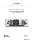
1
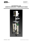
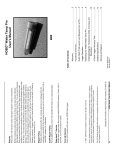
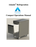
NITRONOX
USER’S MANUAL
Nitronox®
F i e l d U ni t
An a l g e s i a S ys t e m
www.porterinstrument.com/nitronox
REF 10223000 Rev. H
Safety Summar y
Warnings and Precautions
W a r n i n g : T h e Nitronox® Inhalation Analgesia apparatus is a specialized medical device designed
to be operated as indicated herein. Only personnel trained in its use should operate it. Carefully read
this manual prior to operation and use.
Warning: The unit should be operated in an upright position. If the nitrous oxide cylinder is in a valvedown position while the valve is open, liquid may be expelled through the vent passages. This liquid,
nitrous oxide, can cause burn by freezing on exposed skin.
SELF-ADMINISTRATION VS. ASSIST TO SELF-ADMINISTRATION
Warning: Patient must self-administer. Encourage patient to fully self-administer. Self-administration
is a safety feature of the demand flow Nitronox in that, if for any reason the patient becomes over
sedated, the patient will be unable to successfully hold the mask in a tight seal position on the face. The
result will be that the mask falls away from the face and the demand flow will cease, allowing the patient
to breathe room air in through the mouth or nose.
Warning: If a patient is unable to fully self-administer, and the medical professional provides an assist
to placement of the mask in a sealing position on the face, maintain patient observation to prevent over
sedation under any conditions. Discontinue the assistance in mask placement immediately upon any
observation of over sedation; remove the mask from the face entirely. Never use a mask strap to hold the
mask to the face. Never force the mask on the face; the patient must always be spontaneously breathing.
Warning: DO NOT USE if the mixture pressure is out of the green band. If the mixture pressure drops
below the green band (30 PSI) during a breathing cycle, and the whistle alarm sounds, the nitrous
oxide supply is depleted or shut off. When this happens, the unit will administer 100% oxygen. It is
acceptable to administer oxygen in this manner.
Warning: If the whistle alarm sounds continuously, immediately discontinue use and shut off the gas
supply. Contact Porter Instrument Division or Authorized Distributor for repair.
Caution: Always turn on cylinder valves slowly and fully.
Caution: Disconnect the oxygen supply and close the nitrous oxide valve when the unit is not in
operation. Never store the unit with the nitrous oxide valve open.
Delivery Checkout
Examine the shipping carton for signs of external
damage. Remove the contents from the carton
and inspect for visible damage or missing parts.
If any damage is discovered or suspected and/or
parts are missing, notify Porter or authorized
distributor immediately.
User Responsi bility
The Nitronox® Inhalation Analgesia apparatus is
designed to perform to specifications when
operated and maintained as instructed herein.
Replace defective or worn parts immediately. Do
not use a defective product. Do not repair this
product other than in accordance with the written
instructions provided by Porter. The user has the
sole responsibility for any malfunction which
results from improper use, faulty maintenance,
improper repair, damage or alterations by anyone
other than Porter.
Note: Cylinders from Porter are shipped
EMPTY.
Warning:
Nitronox® Analgesia units are
intended to be used by medical personnel trained
in its use and the use of nitrous oxide and
oxygen for medical applications.
livery Checkout
Examine the shipping carton for signs of external
damage. Remove the contents from the carton
i
Nitronox® Field Unit Inhalation Analgesia Machine - Serial Number:
Table of Contents
Safety Summary; Warnings and Precautions; Self-Administration ....................................... i
Section 1 Description ........................................................................................................... 1
1.1 Capacities ........................................................................................................... 1
1.2 Mixture Setting ................................................................................................... 1
1.3 Ambient Temperature Limits .............................................................................. 1
1.4 Safety Features .................................................................................................. 1
Section 2 Operation .............................................................................................................. 2
2.1 Preparation for Use ............................................................................................ 2
2.2 Functional Tests ................................................................................................. 3
2.3 Operation ............................................................................................................ 3
2.4 Nitrous Oxide Cylinder Replacement ................................................................. 4
2.5 System Security ................................................................................................. 6
2.6 Mixture Pressure Adjustment ............................................................................. 6
Section 3 Service ................................................................................................................. 7
3.1 Cleaning ............................................................................................................. 7
3.2 Inspection and Calibration .................................................................................. 7
3.3 Cylinder Filling Specifications ............................................................................ 7
3.4 Troubleshooting.................................................................................................. 7
Section 4 Replacement Parts ............................................................................................... 8
Section 5 Warranty ............................................................................................................... 9
List of Illustrations
Figure 1
Figure 2
Figure 3
Figure 4
Figure 5
Figure 6
Figure 7
Figure 8
Figure 9
Figure 10
Figure 11
Figure 12
Figure 13
Figure 14
Figure 15
Figure 16
®
Nitronox Field Unit Analgesia System .............................................................. iii
Removing Mixer from Case ................................................................................ 2
Nitrous Oxide Cylinder and Mixer ....................................................................... 2
Attaching the Cylinder ......................................................................................... 2
Reinstalling Assembly in the Case...................................................................... 2
Demand Supply Valve ........................................................................................ 3
Set-Up Operation ................................................................................................ 4
Patient Administered ........................................................................................... 4
Valve Knob Fully Closed ..................................................................................... 4
Removal from Carrying Case .............................................................................. 5
Separating the Cylinder ...................................................................................... 5
O-Ring Placement ............................................................................................... 5
Reinstalling Assembly in Case ............................................................................ 5
System Security .................................................................................................. 6
Mixture Pressure Adjustment .............................................................................. 6
Exploded Parts Illustration .................................................................................. 8
ii
Figure 1. Nitronox® Field Unit Analgesia System
iii
Section 1
The Nitronox® Field Unit, shown in Figure 1,
is a portable inhalation analgesia system
designed to deliver a 50% oxygen / 50%
nitrous oxide analgesic gas mixture to a
patient via patient-held demand [supply]
valve and face mask or a disposable
mouthpiece. It includes a single mission
supply of nitrous oxide and utilizes an
external supply of oxygen.
1.1 Capacities
The Nitronox system is capable of delivering
peak flows of up to 100 liters per minute at
normal breathing rates for approximately 30
minutes with one cylinder of nitrous oxide (14
ounces) and a continuous high pressure O2
supply.
1.2 Mixture Setting
Mixture concentration is factory set at 50%
nitrous oxide and 50% oxygen (+/- 5
percentage points oxygen).
1.3 Ambient Temperature Limits
Normal Operation
40ºF (5ºC) Minimum
100ºF (38ºC) Maximum
Operation Below 40ºF
Start with a “warm” Nitronox Field Unit
(stored at 60ºF or higher). Move Unit into
the cold ambient area and begin mission
immediately. Nitrous Oxide delivery %
becomes lower with colder temperatures
(becomes oxygen enriched), and also lower
over the mission time.
De s c r i p t i o n
1.4 Safety Features
Several automatic safety features allow the
medical professional to attend to patient
injuries while the Nitronox is in use.
1.4.1
Oxygen Fail-Safe
If the oxygen line pressure drops or becomes
disconnected, the nitrous oxide flow and the
mixture supply demand valve flow stop
automatically. If the nitrous oxide supply runs
out or is shut off, the supply valve continues
to provide 100% oxygen at a reduced peak
flow of about 40 LPM.
1.4.2
Oxygen Enrichment
If the patient takes abnormal shallow breaths
(100 to 200 mL tidal volume), oxygen
concentration automatically increases. Also
increases in colder ambient temperatures
(see 1.3 Ambient Temperature Limits).
1.4.3
Mixer Pressure Alarm
If the nitrous oxide supply runs out or is shut
off, the whistle alarm sounds during
breathing cycles and the supply valve
continues to provide 100% oxygen at a
reduced peak flow of about 40 LPM. The
whistle alarm also sounds when the mixture
concentration changes due to a gas mixture
regulator seat malfunction.
1
®
Section 2 Operation
The Nitronox Field Unit system is a ready-to-use unit and
needs only an external supply of oxygen. Note:
Cylinders from Porter are shipped EMPTY.
2.1 Preparation for Use
Make sure that the nitrous oxide cylinder is replaced after
each use. One full N2O cylinder contains about a 30
minute supply, long enough for most single missions.
1. Remove the nitrous oxide cylinder and mixer assembly
from the shipping cartons.
2. Remove the mixer assembly from the carrying case as
shown in Figure 2. Remove small red caps.
5. Check the connection by opening the cylinder valve
slightly and listening for leakage. If a “hissing” noise is
heard, close the valve and remove the cylinder.
Recheck to ensure that the O-ring shown in Figure 3 is
present and in good condition. Re-assemble and check
the connection again to be sure that there is no
leakage or “hissing” noise.
3. Remove the cap from the outlet of a fresh cylinder of
nitrous oxide. Inspect the female connector on the
mixer to assure that the O-ring is in place as shown in
6. If the connection is not leaking, close the valve. DO
NOT store the unit with the cylinder valve open.
Warning: If the cylinder is not in an
upright position when the valve is
open, liquid nitrous oxide can flow
through the vent passages and cause
burns by freezing exposed skin.
7. Install the cylinder / mixer assembly in its case as
shown in Figure 5. Make sure that the mixture
pressure gauge is visible. The apparatus is now ready
for use.
Figure 3.
4. Attach the nitrous oxide cylinder to the mixer assembly
by turning the hand-wheel clockwise until it is “handtight” as shown in Figure 4.
2
2.2 Functional Tests
®
Prior to first using the Nitronox unit and once a week
thereafter, perform the following tests:
9. Disconnect the gas supply/delivery hose at the outlet
on top of the mixer. It is now ready for storage.
Warning
1. Connect the nitrous oxide cylinder to the mixer, per
procedure in 2.1.
Always operate in an upright position (+/30ºfrom vertical). The nitrous oxide cylinder
outlet should always be elevated above the
base, particularly for cold temperature
operation.
2. Uncoil the oxygen supply hose from the case.
3. Remove the gas supply / delivery hose from the case
and connect to the male portion of the quick
disconnect fitting on top of the mixer.
Warning
4. Connect the oxygen hose to a 50 - 55 PSI oxygen
supply. Turn on the oxygen supply and verify that
mixture pressure shown on the mixer pressure gauge
is 30 - 35 PSI (within the green band). (Adjust per
Section 2.6.)
Patient must self-administer at all times.
Warning
5. Turn on the nitrous oxide cylinder by turning the
cylinder valve knob counterclockwise. Verify that there
is no leakage at the connections or relief valve by
listening or by applying a soap solution around the
various fittings. If the whistle alarm sounds
continuously, immediately discontinue use and shut off
gas supply. Contact Porter for repair.
DO NOT USE when the mixture pressure is out
of the green band. If the mixture pressure
drops below the green band (30 PSI) during a
breathing cycle, the whistle alarm sounds
indicating that the nitrous oxide supply is
depleted or shut off. Administration of 100%
oxygen with this condition is acceptable.
6. Cup/seal mouth on hand and hand on demand valve.
Blow into the small test holes (Figure 6) on the back of
the demand valve. Ensure that the valve energizes by
hearing the high flow exit from the valve.
Caution: Always turn on cylinder valves
slowly and fully.
2.3 Operation
®
To operate Nitronox , refer to Figure 7 and:
1. Unzip the case top and uncoil the oxygen inlet hose (1)
from the case. Connect the external, regulated oxygen
supply (2) to the DISS oxygen fitting on the oxygen
inlet hose. Set the oxygen supply pressure to 45 - 60
PSI, preferably within 50 - 55 PSI.
2. Remove the mixture gas supply hose w/ demand valve
(3) from the case and connect it to the male portion of
the quick disconnect fitting (4) on top of the mixer.
3. Turn on the oxygen supply (2) and open the nitrous
oxide cylinder by turning the valve knob (5)
counterclockwise.
7. Close the nitrous oxide cylinder valve and (cup hand)
blow into the small test holes (Figure 6) on the back of
the supply valve. Ensure that the valve energizes by
hearing the high flow exit from the valve. As the nitrous
supply depletes the pressure in the hose, the whistle
will sound with each test.
4. Observe the mixture pressure gauge (6). Normal is 30
- 35 PSI (green band) for static, no flow, condition. The
pressure will decrease slightly during each breathing
cycle by the patient.
Note
If the mixture pressure drops below 30 PSI and whistle
alarm sounds during breathing cycle, the nitrous oxide
cylinder valve is closed or the cylinder is empty.
8. Shut off the oxygen supply and blow (cup hand) into
the small test holes in the back of the valve (Figure 6)
once more. Verify that the mixture pressure drops to
zero and that flow through the valve stops.
3
Caution
When the unit is not in use, ensure that the
nitrous oxide cylinder is off and that the
oxygen supply is disconnected or off.
Caution
The mixer bleeds off oxygen at a constant rate
of 125 mL per minute when the oxygen supply
is connected and turned on. This bleed, over
time, can deplete the oxygen supply.
Caution
Make sure the nitrous oxide cylinder is
replaced after each use. One cylinder contains
approximately a 30-minute supply which is
long enough for most single missions.
2.4 Nitrous Oxide Cylinder Replacement
1. Make sure the nitrous oxide cylinder valve is in a fully
closed position by turning the valve knob (Figure 9)
clockwise until it stops. Ensure that the oxygen supply
to the unit is off and disconnected.
5. Attach a face mask (7), or a mouth piece to the supply
valve (8). Instruct the patient to hold the face mask
lightly on the face, covering the nose and mouth or
seal lips over the mouth piece as shown in Figure 8.
Instruct the patient to breathe normally.
Warning
Patient must self-administer at all times.
6. After use, turn off all cylinder valves and disconnect
the oxygen supply. Clean the valve. Dispose of the
mask or mouthpiece. Prepare the apparatus for the
next use.
4
2. Remove the mixer assembly from the carrying case as
shown in Figure 10.
4. Continue by removing the cylinder and valve
assembly. Tag the cylinder to show it is no longer full.
Return the cylinder to a secure storage area.
Caution
Full cylinders have a cap on the outlet. Always
assume that a cylinder without this cap is no
longer full.
5. Remove the cap from the outlet of a fresh cylinder of
nitrous oxide. Inspect the female connector on the
mixer to assure that the O-ring (Figure 12) is in place.
Attach the cylinder to the mixer assembly by turning
the hand-wheel clockwise until “hand-tight.”
6. Check the connection by opening the valve slightly and
listening for leakage. If hissing is heard, close the valve
and remove the cylinder as described in step 4.
Recheck to ensure that the O-ring shown in Figure 12
is present and in good condition. Reassemble and
check the connection once more to make sure there is
no leak. If the connection is not leaking, close the
valve. Do not store the unit with the valve open.
3. Hold the assembly in the upright position and slowly
unscrew the large hand-wheel by turning it
counterclockwise as shown in Figure 11.
7. Reinstall the mixer / cylinder assembly in its case as
shown in Figure 13. Make sure the mixture pressure
gauge is visible. The apparatus is now ready to use.
Warning
If a hissing sound is heard, stop and recheck
that the cylinder valve is closed and that the
oxygen supply is off.
Warning
If the cylinder is not in an upright position
when the valve is open, liquid nitrous oxide
can flow through the vent passages and cause
freeze burns by freezing exposed skin.
5
2.5 System Security
®
Always store the Nitronox unit in a secure area and use
the double zipper feature to lock the case as shown in
Figure 14. Alternatively, lock up demand supply valve
assembly.
2.6
Mixture Pressure Adjustment (Mixing
assembly will be removed from carrying case and both
gases will be connected and turned on for this
adjustment.)
Warning
When adjusting the mixture pressure, ensure
that the unit is upright. If the cylinder is not
upright while the valve is open, liquid nitrous
oxide can escape through the vent passages
and will cause burns by freezing on exposed
skin.
To adjust the mixture pressure, refer to Figure 15 and:
1. Follow Section 2.4, close cylinder valve (Fig.9),
remove mixer assembly from case (Fig.10), separate
cylinder (Fig.11).
2. (Fig.15) Carefully remove the two red end caps (not
shown) on the mixer assembly.
3. Remove the screws (not shown) that hold the
perforated metal cage (not shown) to the mixer.
4. Keeping tie and cap together, slide off the cable tie (1)
and cap with whistle assembly (2) from the mixture
pressure regulator (3) to expose the mixture pressure
adjustment nut (4) and screw (5).
5. Attach cylinder Section 2.1 Fig.4. Turn on the unit as
described in Section 2.2.
6. Use a wrench to loosen the 7/16 in. hex nut (4),
approximately ¼ turn (counterclockwise). With a
screwdriver, turn the adjustment screw (5) in the center
of the nut clockwise to decrease the pressure and
counterclockwise to increase the pressure. Set the
mixture pressure at the middle of the green band on
the mixture pressure gauge.
7. Cup/seal mouth on hand and hand on demand valve.
Blow into the small test holes (6) on the back of the
supply valve (7) to cause flow through the valve. Make
sure the mixture pressure remains in the green band.
8. Hold the adjustment screw (5) in position with the
screwdriver and tighten the nut (4) with the wrench.
9. Turn off and disconnect the gas supplies.
10. Reinstall the cap with whistle assembly (2) and cable
tie (1) over the regulator (3).
11. Secure the cage to the mixer with the screws. Reinstall
the end caps. Follow Section 2.1 Preparation for Use.
6
Section 3 Service
Field repair is limited to the maintenance and
adjustments described in this manual. Refer all other
repairs to Porter Instrument Division or Authorized
Distributor.
Cylinder must be evacuated by vendor before refilling.
Cylinders were originally cleaned for oxygen use per
spec. RR-C-9016 paragraph 3.8.2. Inspect and reclean if
necessary.
• Valve torque 75 foot pounds.
• The valve outlet is to be covered with a vendor
supplied caplug.
• The paint on the neck of the cylinder is nitrous
oxide blue spats paint #2162.
• The body of the cylinder is clear coated with
DUPONT IMRON 500S to indicate exposure to
elevated temperature. Do not refill if the cylinder
is discolored.
• Fill with 14 oz. of nitrous oxide U.S.P.
• Certify for human consumption. Maintain
certificate of analysis per lot and lot commodity
code number.
• Re-label as necessary. Vendor is to supply
product safety sheet, mark labels with lot
number contents, expiration date and cylinder
size.
• Customer returned empty cylinders to be
accepted and refilled only if they are in good
condition.
3.1 Cleaning
Keep the Nitronox mixer clean by wiping it after each
use with a damp cloth.
Caution
Do not submerge the mixer.
Caution
Do not autoclave any Nitronox components.
3.2 Inspection and Calibration
Porter recommends that you inspect your Nitronox unit
regularly by performing the Section 2.2 functional tests.
Every 2 years Porter also recommends that the unit
calibration be factory certified.
3.3 Cylinder Filling Specifications
The following notes are for use by nitrous oxide vendors,
in conjunction with their standard safety and nitrous
oxide refilling procedures. The customer may photocopy
these specifications and supply the refilling vendor.
3. 4 T r oub le sho o t in g
There are several indications when problems occur in the Nitronox. Use the table below as a guide when there appears to
be a problem.
Indications
Possible Cause
Corrective Action
Leak around nitrous oxide cylinder
Missing or defective O-ring
Replace with Porter PN A-4358-003
Intermittent whistle. Mixture pressure
in green band (or moves below 30 psi
during breathing cycle)
Depletion of nitrous oxide
Replace nitrous oxide cylinder; fill
cylinder before use
Continuous whistle.
Mixture pressure in red band.
Seat leak in oxygen regulator.
Or
Seat leak in nitrous oxide regulator
Or
Seal leak / gas mixture regulator
malfunction
Mixture pressure out of green band.
Mixture pressure out of adjustment.
See mixture pressure adjustment in
Section 2.6.
Mixture pressure in red band, but no
gas supply hooked up.
Defective mixture pressure gauge.
Replace mixture pressure gauge
Porter PN A-4358-004
No mixture pressure. Unit does not
operate.
No oxygen supply.
Check oxygen supply.
7
Discontinue use. Return to Porter for
service.
Section 4 Replacement Parts
The following replacement parts may be obtained from Porter.
It e m
No.
De s cr ipt io n
1
Mixture Pressure Gauge
w / Instructions FM-1243
2
Standoff 1/8 NPT x 1-3/8” Lg.
3
Table Coupling Insert (with Shut
Off)
4
Nipple 1/8 NPT x 1-1/2” Lg.
5
DISS Oxygen Inlet Hose Assembly
w / Instructions FM-1244
6
P art
Numb e r
It e m
No.
A- 43 5 8- 00 4
11
F ac t or y
Re p lac e d
F ac t or y
Re p lac e d
F ac t or y
Re p lac e d
12
De s cr ip t io n
Screw (Phillips Pan Head #6-32 x
3/8” Lg. for Mixer Support Tube)
(Pkg/2) (Sect. 2.6)
Demand Supply Valve Hose
Assembly (Fig. 7)
P art
Nu mb e r
A- 43 5 800 1
91 1 2 0 52 3
13
Demand Supply Valve (Fig. 7)
91 1 2 0 02 8
14*
Users Manual
10 2 2 3 00 0
A- 43 5 8- 00 5
15*
Users Placard
64 9 1 6 10 0
Cable Tie (Pkg/3) (Fig. 15)
A- 43 5 8- 00 0
16
Caplug Bottom (Sect. 2.6)
62 9 0 5 52 6
7
Whistle Assembly (less Orifice)
(Fig. 15)
20 1 3 2 50 2
17
Caplug Top (Sect. 2.6)
20 1 0 8 70 0
8
Alarm Cap (Fig. 15)
10 1 8 3 00 0
18
9
Mixer Support Tube (Sect. 2.6)
30 1 1 3 80 0
19
Nitrous Oxide Cylinder (1 New;
Empty) (Fig. 7)
O-ring for Hand Tight Nut (Pkg/3)
(Fig. 12)
C- 1 7 0300 0
A- 43 5 800 3
Soft Case w/Strap
64 9 1 5 80 0
10
*Not Illustrated
17
1
3
12
2
19
10
4
13
11
7
6
9
8
18
16
5
8
CERTIFICATE OF WARRANTY
THIS W ARRANTY IS GIVEN IN PLACE OF ALL OTHER W ARRANTIES, EXPRESS
IMPLIED, OF MERCHANTABILITY, FITNESS FOR A PARTICULAR PURPOSE
OT HERW ISE.
OR
OR
Under no circumstances shall Parker Hannifin Corporation be liable for incidental or consequential damages as those
terms are defined in the uniform commercial code.
Parker Hannifin Corporation, Porter Instrument Division warrants that each product or part shall be free from defects in
workmanship and materials, under normal use and with appropriate maintenance, for one (1) year from the date of
delivery to customer unless otherwise specified in writing. All rubber and plastic parts and accessories are warranted
under the same conditions for a period of ninety (90) days from date of purchase.
No statement or claim about the product by any employee, agent, representative, or dealer of Parker Hannifin Corporation
shall constitute a warranty by Parker Hannifin Corporation or give to rise to any liability or obligation of Parker Hannifin
Corporation.
Parker Hannifin Corporation shall not be liable for any damage, injury or loss arising out of the use of the product, whether
as a result of a defect in the product or otherwise, if, prior to such damage, injury or loss, the product was (1) damaged or
misused; (2) repaired, altered or modified by persons other than Parker Hannifin Corporation; (3) not installed in strict
compliance with applicable codes and ordinances; or (4) not installed by an authorized Parker Hannifin Corporation
dealer. Parker Hannifin Corporation's obligation for breach of this warranty, or for negligence or otherwise, shall be strictly
and exclusively limited to the repair or replacement of the product or part. This warranty shall be void on any product on
which the serial number has been altered, defaced or removed.
ORDERS All orders are to be made through authorized Parker Hannifin Corporation distributors. All billing will be done
through said distributors. Direct orders will be handled through the authorized local dealer as determined by Parker
Hannifin Corporation.
RETURNS All returned merchandise will be handled through the local Parker Hannifin Corporation distributor. No returns
will be accepted unless authorized in writing by Parker Hannifin Corporation and accompanied by the original shipping
invoice. All returns are subject to restocking charge.
Policies subject to change without notice.
T he Q u al i t y S ys t em f or P or ter I ns t r um en t is c er tif i ed t o I SO 13 4 8 5. T h e s c op e of our r eg is tr a t i on
is : T he des i g n, m a nu f ac tur e , dis tr i bu t io n a nd s er v ic i n g of N itr o u s O x i d e - O x yg e n S e da t io n F lo w
Me t er s , G as Sc a v e ng i ng S ys t em s , S te am S ter i l i ze r s , G as D is tr i b ut i on a n d O f f ic e C om m unic at i on
S ys t em s f or us e b y a ph ys ic i an , d en t is t o r l i c ens e d h ea l thc ar e pr o f es s i on a l.
REF 10223000 Rev. H 03/13
9