1
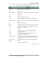
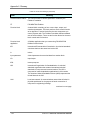
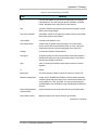
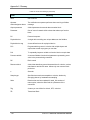
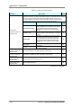
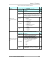
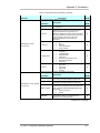
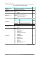
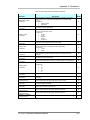
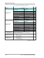
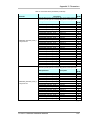
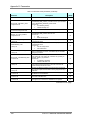
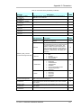
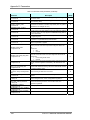
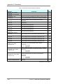
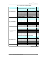
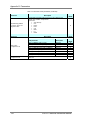
Appendix III: Parameters Table 19: Transducer block parameters (continued) Parameter Mode (R/W) Description The secondary value related to the sensor. Subparameter Mode (R/W) Description A numerical quantity entered by a user or calculated by an algorithm. Digital transducers, unlike their analog versions, can detect faults that make the measurement bad or prevent the actuator from responding. This additional, valuable information will be passed along STATUS with each transmission of a data value in the form of a status attribute. Choices are made in the QUALITY, SUBSTATUS, and Limits subparameters. Choices are: Bad QUALITY Uncertain Good_Noncascade Good_Cascade Choices are: NonSpecific LastUsableValue SubstituteValue SUBSTATUS InitialValue SensorConversionNotAccurate EngUnitRangeViolation Subnormal Choices are: NotLimited LIMITS LowLimited HighLimited Constant Specify the span and units for the auxiliary input channel. VALUE SECONDARY_VALUE In Process TB Subparameter EU_100 EU_0 SECONDARY_VALUE_RANGE In Process TB UNITS_INDEX DECIMAL W W W W W Mode (R/W) Description The engineering unit value that represents the upper end of range of the associated block parameter. The engineering unit value that represents the lower end of range of the associated block parameter. Device Description (DD) units code index for the engineering unit descriptor for the associated block value. This unit must match the AO block units. Choices are: Counts per Second Unitless The number of digits to the right of the decimal point that should be used by an interface device in displaying the specified parameter. W W W W continued on next page LFXG-D Technical Reference Manual 121