1
“A MANAGER” Software for PC
Installation and User Manual
MDE 185
“A Manager vers. 4” for PC
Installation and User Manual
© Copyright by BIFFI Italia. All right reserved
MDE185 /Rev.2
“A MANAGER” Software for PC
Installation and User Manual
3
18-11-2014
Mod F02 new version
D.Bellinzona
A.Battaglia
2
12-05-2010
Mod F02 Operat.
M. Giuliani
A. Affaticati
1
11-02-2009
Mod. Import funct.
M. Giuliani
A. Affaticati
0
21-03-2008
First Issue
G. Riboli
A. Affaticati
Rev.
Date
Description
Prepared
Approved
BIFFI ITALIA has taken every care in collecting and verifying the documentation contained in this
Installation and User Manual.
The informations herein contained are reserved property of BIFFI ITALIA.
© Copyright by BIFFI Italia. All right reserved
MDE185 /Rev.2
BIFFI ITALIA
“A MANAGER” Software for PC
Installation and User Manual
INDEX
1
INTRODUCTION
4
2
INSTALLATION INSTRUCTIONS
4
2.1
2.2
3
To install A Manager PC
To uninstall the Manager PC
USER MANUAL
3.1
3.2
3.3
3.4
3.5
3.6
3.6.1
6
General Notes
Start the Program
Setup
Login
Working mode
Connection to actuator
Connection to ICON /F01 / EFS 2000v4
6
7
7
9
10
10
11
3.6.2
Connection to F02 (EPI 2)
12
3.6.3
Connection to MCU
13
3.7
3.8
4
4
5
Manual discovery of Bluetooth slave devices
Exit from A-Manager
13
14
A-MANAGER FOR ICON/F01/ EFS 2000 V4
4.1
User Interface
4.2
Actuator environment
4.2.1
Actuator Setup
15
15
17
17
4.2.2
Name Plate
18
4.2.3
Valve Data
19
4.2.4
Maintenance
20
4.2.5
Restricted
21
4.2.6
Operation
22
4.2.7
Tools
23
4.3
Options environment
4.4
Examples for ICON/F01/EFS 2000 v4
4.4.1
To Modify the closing torque limit
25
26
26
4.4.2
To Export the actuator data to File
27
4.4.3
To export actuator data to EXCEL file
28
4.4.4
To import the actuator data from file
29
4.4.4.1
To write new data to actuator without changing data of one selected TAB
31
4.4.4.2
To write new data to actuator in TAB by TAB mode
32
4.4.4.3
To copy all data from one logic card to another one
32
4.4.5
To download a new firmware / language to actuator
33
4.4.6
To View Torque / PST / EFS curves
34
A© Copyright by BIFFI Italia. All right reserved
MDE185/Rev.2
Page 2
BIFFI ITALIA
“A MANAGER” Software for PC
Installation and User Manual
4.4.7
To view Alarm Logger
36
4.4.8
To view Data Logger
37
5
A-MANAGER FOR F02 (EPI 2)
38
5.1
User Interface
5.2
Actuator environment
5.2.1
Actuator Setup
38
40
40
5.2.2
Operation
41
5.2.3
Tools
42
5.3
Options environment
5.4
Examples for F02 (EPI 2)
5.4.1
To modify the opening torque limit
44
45
45
5.4.2
To export the actuator data to File
46
5.4.3
To export the actuator data to EXCEL file
47
5.4.4
To import the actuator data from file
48
5.4.5
To set new stroke limits in closure
49
5.4.5.1
Closure by torque
49
5.4.5.2
Closure by position
50
5.5
Distinguish OLD/NEW models for F02-EPI2
5.5.1
A MANAGER Interface differences into new F02-EPI2 version
6
5.5.1.1
OPENING/CLOSING SPEED (ACTUATOR SETUP section)
53
5.5.1.2
OPENING/CLOSING TORQUE (ACTUATOR SETUP section)
54
5.5.1.3
TORQUE (OPERATION section)
54
A-MANAGER FOR MCU 2000 V4
55
6.1
User Interface
6.2
Actuator environment
6.2.1
Actuator Setup
55
58
58
6.2.2
Name Plate
59
6.2.3
Valve Data
60
6.2.4
Maintenance
61
6.2.5
Restricted
62
6.2.6
Operation
63
6.2.7
Tools
65
6.3
7
51
53
Options environment
67
A-MANAGER CONVERSION TOOL
68
7.1
Installation process
7.2
Start the Program
7.2.1
Conversion of file *.set
7.2.2
68
69
69
Conversion of file *.i4k
A© Copyright by BIFFI Italia. All right reserved
70
MDE185/Rev.2
Page 3
BIFFI ITALIA
8
8.1
8.2
8.3
“A MANAGER” Software for PC
Installation and User Manual
USERNAME PROFILES AND PERMISSIONS
Permissions for ICON/F01/EFS 2000v4
Permissions for F02 (EPI 2)
Permissions for MCU 2000v4
9
EXCEPTION MESSAGES
1
Introduction
72
72
74
75
77
MDE 185 is the instruction manual of A-MANAGER version 4.x.x. It includes also instruction manual for “AManager Conversion Tool” , needed to convert files *.set , *.man, and *.i4k (saved with A-Manager version less than
4.0.0 or prjICON4K.exe) to files *.icon, *.f02, *.mcu, readable by A-Manager version 4.x.x.
For A-MANAGER version less than 4.00 refer to instruction manual MAN 660.
2
Installation instructions
Important:
“A MANAGER” for PC installation software consists of two files:
- AManager_PC_4.x.x.msi
- Setup.exe
2.1 To install A Manager PC
Before initiating installation procedure of a new version of A-Manager remove any previously installed version of AManager version 4.x.x (see instructions in par. 2.2 , To Uninstall A-Manager PC). A-Manager versions less than 4.0.0
do not need to be removed.
To start the installation process, double-click on setup.exe file.
A simple wizard will guide you through the installation process:
A© Copyright by BIFFI Italia. All right reserved
MDE185/Rev.2
Page 4
BIFFI ITALIA
“A MANAGER” Software for PC
Installation and User Manual
Click Next.
Agree to End User License Agreement
Select installation folder and then click Next
Click “Next” to begin program installation
When the message “Installation complete” appears click Close.
A link (icon with BIFFI logo named AManager4) to the executable file (AManager.exe) will be created on the desktop
and a new program folder, named “Biffi”, will be added to Start Menu\Program folder.
Double-click one of the links to the executable file or the executable file itself (located in : \destination_folder\bin\) to
run the program.
2.2 To uninstall the Manager PC
In the taskbar click “Start”. Click “Control Panel” and then double click “Add or remove programs”. Click AManager
PC .
Click “Remove” and then “YES”. A-Manager PC will be removed and PC is ready to re-install a new A-Manager
according to instructions of par 2.1 , “To Install A-Manager PC”.
A© Copyright by BIFFI Italia. All right reserved
MDE185/Rev.2
Page 5
BIFFI ITALIA
3
“A MANAGER” Software for PC
Installation and User Manual
USER MANUAL
3.1 General Notes
Warning:
For any information regarding actuator parameters or settings please
refer to the relevant Biffi Actuator documentation.
Wrong parameter settings may cause actuator malfunctions.
Warning:
All parameters changes which were not saved to the internal application
database or sent to the actuator will be lost once the application is
closed.
Warning:
It is assumed that the installation, setting, commissioning, maintenance
and repair works are carried out by qualified personnel and checked by
responsible Specialists.
Warning:
Any repair work other than the operations outlined in this manual will be
strictly reserved to qualified BIFFI ITALIA personnel or to personnel
directly authorised by the Company itself.
Warning:
Whenever the PC will be used in HAZARDOUS AREA as defined by the
applicable rules, it is mandatory to check whether the PC nameplates
indicate their suitability to an hazardous area, and the appropriate
protection degree.
A© Copyright by BIFFI Italia. All right reserved
MDE185/Rev.2
Page 6
BIFFI ITALIA
“A MANAGER” Software for PC
Installation and User Manual
3.2 Start the Program
“A Manager” Software for PC starts with the following screen.
Click “Setup” to select the communication medium.
Enter “Username”, “Password”, “Actuator” , “Operator name” and then click “Login” to run the program.
3.3 Setup
The following screen appears. Select “Channel”, “COM” and “Baud Rate” according to below instructions.
A© Copyright by BIFFI Italia. All right reserved
MDE185/Rev.2
Page 7
BIFFI ITALIA
“A MANAGER” Software for PC
Installation and User Manual
Channel : RS-232
• channel RS-232 is not available for F02 (EPI 2) actuators. Connection to actuator can be done only by
Bluetooth channel
• select Channel RS-232 if the connection between PC and actuator is made by a RS232 cable. In the line COM
select the serial port number of PC. In Baud Rate line select the transmission speed (9600 baud or 115200
baud).
Channel : Bluetooth
• select Bluetooth if a wireless Bluetooth connection between PC and actuator is available. The baud rate is
automatically set at 115200 bit/sec. The new A-manager version 4 is provided of “device discovery function”
that allows to find the Bluetooth slave devices to be linked to PC. It means that pairing operation needed with
A-manager version less than 4 are no longer necessary. The following options are available:
o If the PC has an “integral Bluetooth device” and Service Pack 2, the included Microsoft Generic
Bluetooth Radio Driver is used. The COM number is automatically set.
o If it is used an “external USB Bluetooth adapter” the following two options are available
The USB Bluetooth adapter can works with standard Microsoft Generic Bluetooth Radio and
PC has Service Pack 2, it is not necessary to install any Bluetooth WIDCOMM driver. The
Bluetooth adapter can be used without having before installed its own WIDCOMM driver,
provided together the USB Bluetooth adapter. If a WIDCOMM driver is already installed , it
is suggested to uninstall it and then reboot the PC. The COM number is automatically set.
If USB Bluetooth adapter cannot be used with Microsoft Generic Bluetooth Radio but it is
necessary to install its own WIDCOMM driver , it needs to follow the relevant instructions
to activate the driver. In the above case it needs to set the COM number according to the
configuration of WIDCOMM driver.
To make easier the Bluetooth use, it is suggested to select USB Bluetooth adapter that can use Microsoft Generic
Bluetooth Radio. This is normally indicated in the instruction manual of USB Bluetooth adapter. An alternative way to
understand if the USB Bluetooth adapter can work with Microsoft Generic Bluetooth Radio is to insert the adapter in
the USB port of PC and then to see if in the right corner of the notification area (low bar of PC screen) appears the
blue/white Bluetooth icon . If yes, the adapter is recognized and can work without installing the WIDCOMM driver. If
not, remove immediately the adapter from USB port and proceed to install the WIDCOMM driver provided with the
adapter
Note: right click on the icon “Device manager” and then click “properties”, to view PC resources. Click Hardware,
Device manager, Bluetooth Radios to see the active Bluetooth driver.
Note: after the disconnection of A-manager from an actuator, it needs to wait at least 30 sec before re-connecting the
same actuator.
Note :
•
IrDA operation
This mode is available only if the PC is provided of external RS 232 to IrDA converter/probe ( for instance
ACTiSYS infrared wireless adapter ACT-IR220L+ ). No IrDA driver is requested since the A-Manager works
in RS-232 mode. The maximum baud rate is 9600 baud.
Click “Close” to exit from Setup without any change
or alternatively
Click “Save” to enter the new setup . Click “Close”, click Yes .
Exit from A-Manger by the red “X” on the right upper corner of the “A-Manager- Setup” screen and then double click
the A-Manager icon on the desktop to restart with the new settings.
A© Copyright by BIFFI Italia. All right reserved
MDE185/Rev.2
Page 8
BIFFI ITALIA
“A MANAGER” Software for PC
Installation and User Manual
3.4 Login
•
Enter “Username and Password” :
o Four username are available: Observer, User, Service e Manufacturer (Service and Manufacturer
username are reserved for Biffi authorized personnel use only).
Observer username allows only to view data, export data to file, import data from file, but change data is not allowed.
Default password supplied by BIFFI is “00000000”.
User username allows viewing data, exporting to file and importing from file as Observer can do, in addition the User
profile also to modify data in the Actuator Setup, Valve data, Maintenance, and modify “User and Observer”
passwords.
Default password supplied by BIFFI is “99999999”.
End user can modify the Observer and User password only by entering as User. After entering the new password the old
one ceases to be valid. Therefore it is mandatory “NOT FORGET THE PASSWORD” after the default one has been
modified.
Service username has the User permissions and in addition can modify “Restricted” and “Name Plate” data.
Manufacturer username can modify any data.
Details of permissions relevant to usernames are in the par. 8 , “Username profiles and Permissions”
•
•
•
Enter “Actuator type” :
o Three Actuator types are available : ICON/F01/EFS, F02/EPI 2, MCU
Enter “Operator name” :
o The field is optional. Icon 2000v4 and MCU 2000v4 memorize the last 8 operator name in a register
with data, time and code of the PC. The data can be read by the Maintenance features of A-Manager.
Click “Login”
A© Copyright by BIFFI Italia. All right reserved
MDE185/Rev.2
Page 9
BIFFI ITALIA
“A MANAGER” Software for PC
Installation and User Manual
3.5 Working mode
A-Manager can work in “disconnected” or “connected” mode
In “disconnected” mode the actuator is not connected. A-Manager can work only with files previously exported.
In “connected” mode the actuator is connected to PC and data of actuator can be viewed and changed according to
username.
To work in “disconnected” mode the following options are available:
1. Start of A-Manager program
In Setup , select Channel RS232, select COM not existing in the PC (for instance 99) or
select the available COM for RS-232 but do not connect the cable to actuator, and then click
Save and Close, then click Login
2. A-Manager already working in “connected” mode
In Actuator environment, section Tools, TAB Utility, click Disconnect from actuator
3.6 Connection to actuator
By clicking “Login” the A-Manager interrogates the actuator and asks actuator serial number. Two options are
available:
o Channel RS-232 : if actuator responds A-Manager runs in “connected” mode and the 3 LED’s of
ICON /F01 /EFS/ MCU 2000 actuator flashes few seconds. F02 has no LED’s and no visual
indication on the actuator can be done. Indication of connection status is available in the A-Manager
user interface
o If actuator does not respond, the A-Manager runs in “disconnected” mode.
A© Copyright by BIFFI Italia. All right reserved
MDE185/Rev.2
Page 10
BIFFI ITALIA
•
“A MANAGER” Software for PC
Installation and User Manual
Channel Bluetooth :
o Device discovery function searches slave devices available and shows icons (ICON 2000, or F02, or
MCU2000) and serial numbers (or valve tag), according to actuator configuration
o Click the actuator to be connected
o Click “connect”.
o When connection is established the A-Manager runs in “connected” mode and the three LED’s of
ICON / MCU 2000 actuator flashes few seconds. F02 has no LED’s and no visual indication on the
actuator can be done. Indication of connection status is available in the A-Manager user interface.
o If actuator does not respond, the A-Manager runs in “disconnected” mode.
o after the disconnection of A-manager from an actuator, it needs to wait at least 30 sec before reconnecting the same actuator.
3.6.1
Connection to ICON /F01 / EFS 2000v4
When the list of available ICON/F01/EFS’s appears select the ICON/F01/EFS and then click Connect
A© Copyright by BIFFI Italia. All right reserved
MDE185/Rev.2
Page 11
BIFFI ITALIA
“A MANAGER” Software for PC
Installation and User Manual
3.6.2 Connection to F02 (EPI 2)
When the list of available F02’s appears select the F02 and then click Connect
A© Copyright by BIFFI Italia. All right reserved
MDE185/Rev.2
Page 12
BIFFI ITALIA
“A MANAGER” Software for PC
Installation and User Manual
3.6.3 Connection to MCU
When the list of available MCU’s appears select the MCU and then click Connect
3.7 Manual discovery of Bluetooth slave devices
If the integrated Bluetooth Device Discovery function does not find any Bluetooth device, the following procedure can
be useful to check if really no Bluetooth device is available for connection to PC. The procedure can be used only if
Microsoft Bluetooth radio is used. Exit from A-Manager.
Double click the blue/white Bluetooth icon in the right corner of notification area (low bar in the PC screen).
Select Device and click Add. Click “My device is set up and ready to be found” and then click Next.
A© Copyright by BIFFI Italia. All right reserved
MDE185/Rev.2
Page 13
BIFFI ITALIA
“A MANAGER” Software for PC
Installation and User Manual
The list of available devices appears in the PC screen. Click finish to exit.
3.8 Exit from A-Manager
Click the red X in high right corner and than click YES to exit from program.
A© Copyright by BIFFI Italia. All right reserved
MDE185/Rev.2
Page 14
BIFFI ITALIA
4
“A MANAGER” Software for PC
Installation and User Manual
A-Manager for ICON/F01/ EFS 2000 v4
4.1 User Interface
The user interface is organized in environments and sections. Environments are grouped in the horizontal navigation
bar on the top of the screen. Each environment contains sections that are listed in the vertical navigation bar on the left.
At present two environments are available : Actuator and Options. The following sections are available in each
environment:
Environment
S
E
C
T
I
O
N
Actuator Setup:
Name Plate:
Valve Data:
Maintenance:
Restricted:
Operations:
Tools:
Actuator
Actuator Setup
Name Plate
Valve data
Maintenance
Restricted
Operations
Tools
Environment
S
E
C
T
I
O
N
Options
Modify Config
Password
Object List
it contains actuator configuration settings
it contains actuator name plate data
it contains data about the valve onto which the actuator is mounted
it contains maintenance and diagnostics information;
it contains actuator advanced settings.
it is used to remotely send commands to actuator and to read status and alarm information;
it is used to read and write Card Reports. This section also permits to import and export
configurations from and to files, reading and updating actuator firmware and to send various
utility commands to actuator.
Modify config: it is used to change the A-Manager settings. The following data can be modified:
• Communication data:
Channel, COM n°, Speed
• Language
Italian or English
Password:
it allows to change “observer” and “user” password
Object list.
It allows to see the object list number and the description of the object function
If username is not enabled to access to a particular a section or environment, the relative button will be disabled.
Sections are organized in TAB’s. Each TAB contains a subset of information that can be read from and written to the
actuator. The data of TAB’s are grouped according to organization in the actuator local menu.
Once Environment and Section are selected, click TAB of data to be viewed.
A© Copyright by BIFFI Italia. All right reserved
MDE185/Rev.2
Page 15
BIFFI ITALIA
“A MANAGER” Software for PC
Installation and User Manual
EXIT
Environment (active = orange)
Sections (active = orange)
SW revision
Working mode/baud/channel
Actuator type
Actuator serial number
Username
TAB
A© Copyright by BIFFI Italia. All right reserved
MDE185/Rev.2
Page 16
BIFFI ITALIA
“A MANAGER” Software for PC
Installation and User Manual
4.2 Actuator environment
The Actuator Environment contains information about configuration settings and actuator management.
Click Actuator to select the environment.
Click the Section to be viewed. If the A-Manger works in “connected” mode, all data of selected section are read from
actuator. Click the TAB to view the data on the PC screen. Use button Refresh to read again all data of selected TAB.
Use button Modify to activate the “modify data” option. Modify the data in the selected TAB and then click Send to
send all data of selected TAB to actuator or click Undo if data should not be changed. Only data of the selected TAB
will be sent to actuator. Option Modify and Send are enabled according to username profile and permissions. In
Observer username the options Modify and Send are disabled. In “disconnected” mode Modify and Send can be used
to change values of parameter of previously imported file. The modified data can only be saved by the export file/excel
functions.
4.2.1 Actuator Setup
“Actuator Setup” contains the actuator settings and it allows to view and modify the configuration of actuator according
to permission of username.
Data are grouped in TAB (Fail Safe & Interlock, 2-Speed Timer, Miscellaneous , etc), according to the same
organization in the actuator local menu. Use the ICON/F01/EFS 2000 v4 instruction manuals to configure the actuators
parameters. The following example allows to view or change ESD parameters :
• Click “Actuator Setup”, click “ESD Setup”
A© Copyright by BIFFI Italia. All right reserved
MDE185/Rev.2
Page 17
BIFFI ITALIA
“A MANAGER” Software for PC
Installation and User Manual
4.2.2 Name Plate
“Name Plate” contains the actuator name plate and it is possible to view and modify the actuator data according to
permission of username. Data are grouped in TAB (Actuator data, Actuator Speed, Power Supply , etc), according to
the same organization in the actuator local menu. Use the ICON/F01/EFS 2000 v4 instruction manuals as reference to
see name plate parameters description.
The following example allows to view or change the TAB “Actuator Data” :
• Click “Name Plate”, click “Actuator Data”
A© Copyright by BIFFI Italia. All right reserved
MDE185/Rev.2
Page 18
BIFFI ITALIA
“A MANAGER” Software for PC
Installation and User Manual
4.2.3 Valve Data
“Valve data” contains the data relevant to the valve and allows to view and modify the above data according to
permission of username. Data are grouped in one only TAB (Tag, Serial Number, etc), according to the same
organization in the actuator local menu. Use the ICON/F01/EFS 2000 v4 instruction manuals to see valve parameters
description.
Click “Valve Data” on the Main Menu. To view the valve data values
A© Copyright by BIFFI Italia. All right reserved
MDE185/Rev.2
Page 19
BIFFI ITALIA
“A MANAGER” Software for PC
Installation and User Manual
4.2.4 Maintenance
“Maintenance” contains the data relevant to the actuator maintenance and allows to view and modify the above data
according to permission of username. Data are grouped in TAB (Data Logger, Alarm Log, Torque Curve, etc),
according to the same organization in the actuator local menu. Use the ICON/F01/EFS 2000 v4 instruction manuals to
see data description. The following example allows to view or change the “Data Logger” :
• Click “Maintenance” and then “Data Logger ”
A© Copyright by BIFFI Italia. All right reserved
MDE185/Rev.2
Page 20
BIFFI ITALIA
“A MANAGER” Software for PC
Installation and User Manual
4.2.5 Restricted
“Restricted” contains advanced actuator settings. It is possible to view data, but to modify them is allowed only with
Service or Manufacturer username. Data are grouped in TAB (One, Two, etc), according to the same organization in
the actuator local menu. The following example allows to view or change the TAB “One” :
• Click “Restricted”, click “One”
A© Copyright by BIFFI Italia. All right reserved
MDE185/Rev.2
Page 21
BIFFI ITALIA
“A MANAGER” Software for PC
Installation and User Manual
4.2.6 Operation
“Operation” is active only if A-Manager works in “connected” mode and can be used to send commands to actuator
and read status and alarm information.
Confirmation is required to enter in this section. To send commands to actuator is available only according to
permission of username , if the selector is in LOCAL and if the appropriate actuator setting was done. On the PC
screen are present the same information available in the actuator local displays and also the value of the main important
variables (torque, speed, voltage, etc.)
The button Output Contacts allows to see the status of output relays , Monitor relay and Auxiliary relays Asi. The
button “Alarm/Warning” allows to see the list of alarms and warnings. The line of present Alarms and Warnings are
red. The button Bus Information allows to see various data relevant to Bus Interface (if it is present). The button Other
Info allows to see various data relevant internal counters, A to D converter, etc. The button Reset Alarm/ Warning
allows to send a “reset Alarm and Warning” command to actuator.
Alarm / warning list
A© Copyright by BIFFI Italia. All right reserved
MDE185/Rev.2
Page 22
BIFFI ITALIA
“A MANAGER” Software for PC
Installation and User Manual
4.2.7 Tools
“Tools” is used to read and write Card Reports. This section also permits to import and export configurations from and
to the files, reading and updating actuator firmware and to send various utility commands to actuator. Data are grouped
in TAB , Card report, Import/Export, Firmware/Language, Utility, etc). Availability of the various write operations is
according to username permission.
The TAB “Card report” allows to see information relevant to electronic cards present in the actuator.
The TAB “Import/Export” allows the following :
Export file: in connected mode it allows to read from actuator and save the present set of actuator data in a file. Files
are exported with extension *.icon. In disconnected mode the data in the A-Manager application memory are saved.
Export EXCEL: in connected mode it allows to read from actuator and save the complete (or per section) set of
actuator data in an EXCEL file. In disconnected mode the data in the A-Manager application memory are exported.
Import file: read the complete (or per section) set of actuator data , previously saved, and then send them or not to
actuator. Files previously exported with A-Manager version less than 4.00 (*.set , *.man, *.i4k) need the conversion in
files compatible with the version 4.0.0 . See par. 7, “A-Manager Conversion tool”
Few data can be written to actuator only in TAB by TAB mode (see par. 4.4.4.2 To write new data to actuator in TAB
by TAB mode), and most of maintenance data cannot be written to actuator. See the list of the above data in par. 8.1
“Username profiles and permissions”, Table 1 and Table 2
Import file *.pic: import stroke limits data from a file *.pic
The TAB “Firmware/ Language” allows to download a new firmware and language file to actuator.
A© Copyright by BIFFI Italia. All right reserved
MDE185/Rev.2
Page 23
BIFFI ITALIA
“A MANAGER” Software for PC
Installation and User Manual
The TAB “Utility” allows the following commands :
• Connect /Disconnect to/from actuator (connected or not connected working mode). In Bluetooth mode, after
the disconnection of A-manager from an actuator, it needs to wait at least 30 sec before re-connecting the same
actuator.
• Change Baud Rate , see also par. 3.3 Setup
• Wink: in connected mode the command causes the 3 LED’s of actuator to blink
• Set Icon Selector: in connected mode the command allows to virtually change the position of actuator local
selector from Local, Off, and Clear. Press Local to move the virtual selector to Local, press Off to move the
virtual selector to Off . The control will be restored to real actuator local selector by sending Clear or by
closing the communication channel between actuator and PC or by re-powering the actuator.
• Change Bluetooth module name: it allows to change the actuator name ( with Bluetooth channel) from actuator
serial number to valve tag.
Below is the screen of the TAB “Utility”.
Change Bluetooth module name
The procedure is the following:
• Click Modify, select Serial Number or Valve Tag and then click Send. If Bluetooth uses the Microsoft driver
to update the name it need to exit from A-Manager, reboot the PC or remove and then re-insert the Bluetooth
adapter, re-power the actuator and than run again the A-manager. Alternatively use the manual discovery of
Bluetooth device
• If a WIDCOM driver is used the procedure to update depends on the driver type. Refer to instruction manual
of driver to update the Bluetooth name.
A© Copyright by BIFFI Italia. All right reserved
MDE185/Rev.2
Page 24
BIFFI ITALIA
“A MANAGER” Software for PC
Installation and User Manual
4.3 Options environment
The Options environment allows the user to modify the application configuration parameters and passwords
management. Three sections are available: Modify Config., Password, Object list
Modify config: it is used to change the A-Manager settings. The following data can be modified:
• Communication data:
RS-232, BluetoothTM
• COM Port number:
the number of the COM port to open
• Connection speed:
9.600bps or 115.200bps
• Language
Italian or English
Click Save configuration and then EXIT from A-Manager and run the program again.
Password:
it allows to change “observer” and “user” passwords. Press “Confirm” to save changes.
Changes are applied with no need to restart the application.
Object list.
It allows to see the object list number and the description of the object function. Click Export
Object list to export in an Excel file. Select folder and name and then click save
A© Copyright by BIFFI Italia. All right reserved
MDE185/Rev.2
Page 25
BIFFI ITALIA
“A MANAGER” Software for PC
Installation and User Manual
4.4 Examples for ICON/F01/EFS 2000 v4
4.4.1 To Modify the closing torque limit
With A-Manager working in connected mode, click Actuator environment, and Actuator Setup section.. The AManager reads the actuator setup parameters from actuator to A-Manager application program memory.
Reading data from actuator is done by object. Click TAB “Stroke limits and Torque setup”, then click “Modify”. The
Modify operation is not allowed with username Observer, according to permission profile.
Enter the new closing torque value (85%) and then click Send. A dialog file advice that the new value will not be
written in the actuator memory if the local selector is in Local or Remote. Click Yes. “Send” command writes to
actuator all data of selected TAB
The new value will be sent to actuator and then Modify button disabled. New modify session is available by clicking
again “Modify”. Click “Refresh” to check the change has done. Refresh command reads only data of selected TAB.
A© Copyright by BIFFI Italia. All right reserved
MDE185/Rev.2
Page 26
BIFFI ITALIA
“A MANAGER” Software for PC
Installation and User Manual
4.4.2 To Export the actuator data to File
In the Actuator environment, Tools section, Import/Export tab, press “Export file”. The following save file dialog will
appear.
Select destination folder and name of file and press Save. A files with extension *.icon will be created. The proposed
name is a string of characters that includes actuator serial number, date and time.
Press YES to read the complete set of data from actuator, Press No to save the data present in the current application
memory. It is important to understand the difference: data currently in the application memory could or couldn’t be the
same data of the actuator (especially maintenance data can change very often). So to be sure to export hot actuator data,
press “Yes” when asked to read data from actuator.
A message will inform when the export process is complete.
Now the configuration is saved in the specified files. Later it is possible to import this configuration by pressing the
“Import file” button.
Export data is made by object number. If some data is not correct or out of limits or communication is lost an error
message will appears with the Abort, Re-tray, Ignore options. The Object list in the Options environment can help in
discovering the incorrect data .
A© Copyright by BIFFI Italia. All right reserved
MDE185/Rev.2
Page 27
BIFFI ITALIA
“A MANAGER” Software for PC
Installation and User Manual
4.4.3 To export actuator data to EXCEL file
The function allows saving in an Excel file the complete or “per section” actuator data.
In the Actuator environment, Tools section, Import/Export tab, press “Export Excel”. The following file dialog appears:
Select the sections to be saved , then move to Torque curves and select curves to be saved. Repeat the procedure with
PST curves and EFS curves in case of EFS 2000v4.
Press Confirm. The following file dialog appears.
Select destination folder and name of file and press Save. A files with extension *.xls will be created. The proposed
name is a string of characters that includes actuator serial number, date and time.
Press YES to read the complete set of data from actuator, Press No to save the data present in the current application
memory. It is important to understand the difference: data currently in the application memory could or couldn’t be the
same data of the actuator (especially maintenance data can change very often). So to be sure to export hot actuator data,
press “Yes” when asked to read data from actuator.
When conversion is finished the new file will be open. Export data is made by object number. If some data is not
correct or out of limits an error message will appear with the Abort, Re-tray, Ignore options. The Object list in the
Options environment can help in finding the description of incorrect data .
A© Copyright by BIFFI Italia. All right reserved
MDE185/Rev.2
Page 28
BIFFI ITALIA
“A MANAGER” Software for PC
Installation and User Manual
4.4.4 To import the actuator data from file
In the Actuator environment, Tools section, Import/Export tab, press “Import file”. Only files with *.icon extension can
be imported. See par. 7, A-Manager Conversion Tool, to import file with different extension. A-Manager can work
either in “connected” mode or in “not connected” mode. In “connected” mode the imported data can be sent or modified
and then sent to actuator. In “not connected” mode the imported data can be modified and then exported in a new file.
Select the file to be imported and then click Open. Now the actuator data are in application memory of A-Manager.
The above dialog file appears.
Press Cancel if data should not be transferred to actuator or if working mode is “disconnected”
Select the “Section” of data to send to actuator and then press OK. Only “Section” selection is available, sending data
of selected TAB is described in the below examples. Selected “Sections” will be sent to actuator only if enabled by
the username profile and will be memorized in the actuator memory only if the actuator local selector is in OFF .
Select “Name Plate” and “Overwrite serial number on actuator” to change all Name Plate data included “actuator serial
number”. Place the actuator local selector in OFF before pressing OK or alternatively change virtually the actuator
A© Copyright by BIFFI Italia. All right reserved
MDE185/Rev.2
Page 29
BIFFI ITALIA
“A MANAGER” Software for PC
Installation and User Manual
selector position by the command Change Icon Selector available in Actuator environment, Tools, Utility, according to
instructions in par. 4.2.7, Tool. Few data cannot be written to actuator or can be written only in TAB by TAB mode (see
par. 8.1, Table 1 and 2.
Import data is made by object number. If some data is not correct or out of limits an error message will appear. With the
Abort, Re-tray, Ignore options. The Object list in the Options environment can help in finding the description of
incorrect data.
A report is generated if some object is not supported or out of limits.
In the above report, the configuration data can be sent to actuator since objects are not supported by actuator
In the above case a lot of objects are out of limits. The suggested procedure is the following:
• Click Cancel
• Change to “disconnected” working mode
• By the Object list and using the functions Modify and Send enter the correct values
• Export the correct data in a new *.icon file
• Change to “connected” working mode
• Import the new corrected *.icon file and then download to actuator
A© Copyright by BIFFI Italia. All right reserved
MDE185/Rev.2
Page 30
BIFFI ITALIA
“A MANAGER” Software for PC
Installation and User Manual
4.4.4.1 To write new data to actuator without changing data of one selected TAB
Export the present actuator configuration in a file “oldname.icon” by the A-Manager Export to file function
Import the new configuration file *.icon by the A-Manager import function. Select Sections and then click OK to send
data to actuator. In the below example, sections “Name Plate” and “Valve Data” will not be written to actuator even if
allowed by the username profile and permissions. Click OK to send data to actuator
Now import the old configuration previously exported and click Cancel
The old configuration is now present only in the A-Manager application memory. Select the TAB containing the old
data to send to actuator (e.g. Actuator environment, Actuator setup section, ESD setup)
Click Modify
Click Send. Only data of selected TAB (ESD setup) will be sent to actuator
Exit and then start again the A-Manager
The above examples allows to write a new configuration file to actuator without changing the TAB ESD setup and
sections Valve data and Name Plate
A© Copyright by BIFFI Italia. All right reserved
MDE185/Rev.2
Page 31
BIFFI ITALIA
“A MANAGER” Software for PC
Installation and User Manual
4.4.4.2 To write new data to actuator in TAB by TAB mode
Import the new configuration file *.icon by the A-Manager import function
Click Cancel to maintain data in the A-Manager application memory
TAB’S
Write the new data to actuator by the selection of each TAB and then using the command Modify and Send for each
TAB.
4.4.4.3 To copy all data from one logic card to another one
The following procedure works only with username Service or Manufacturer. With username Service only the “card
report” TAB will not written to actuator.
Place the actuator in fully open or closed position
Export the present actuator configuration in a file *.icon by the A-Manager Export to file function
Exit from A-manager. Remove the logic card from actuator and install a new one. Start again A-Manager .
Import the previously exported file.
Select all sections and click OK to write data to actuator.
Now it needs to write to actuator the data writable only in TAB by TAB mode (see par. 4.4.4.2 and par 8.1 Table 1 and
2 “Username profiles and permissions”).
Now the new logic card has the same data of the old one, also stroke limits are the same.
Use “Restore” 0% or 100% command to set the present actuator position (fully open or closed).
The above procedure can be performed only with username “Service” or “Manufacturer”
A© Copyright by BIFFI Italia. All right reserved
MDE185/Rev.2
Page 32
BIFFI ITALIA
“A MANAGER” Software for PC
Installation and User Manual
4.4.5 To download a new firmware / language to actuator
The function can be used only in “connected” mode and allows to download a new firmware and language to actuator.
The files to write in the actuator memory should have *.bin extension.
• New Firmware download
In Actuator environment , click section Tool. Click Tab “Firmware/language”. In Kernel program click “Write To
Actuator”. Select folder and “Kernel” file, then click Open. File will be downloaded to actuator.
Repeat the procedure to write to actuator flash memory the files “Erase” and “Firmware”. Click Check Firmware to
verify the data are correct. Click Transfer to initiate transferring the new firmware from actuator flash memory to the
actuator program memory”. When the operation ends it needs to re-power the actuator. Also it need to close the AManager program and restart it again.
• New Language download
Use the same procedure to download a new language.
Click section Tool. Click “Language”. Select folder and language file. File will be downloaded to actuator.
Downloading firmware and language can require few minutes.
A© Copyright by BIFFI Italia. All right reserved
MDE185/Rev.2
Page 33
BIFFI ITALIA
“A MANAGER” Software for PC
Installation and User Manual
4.4.6 To View Torque / PST / EFS curves
In “connected” mode the function allows to view the torque curve memorized in the actuator memory. In “not
connected” mode the function allows to view the torque curves previously saved in a file by means of the “Export file”
function. So in “not connected” mode it needs to use the “Import file ” option before viewing the torque curves.
In Actuator environment and Maintenance section click TAB “Torque curves”. Select curves to view.
Click Details to view details of the selected curves. Select Details also to set the “reference curves”, (signature). Click
Full Screen View to utilize the full screen. Right click of mouse to print and save as images the curves
A© Copyright by BIFFI Italia. All right reserved
MDE185/Rev.2
Page 34
BIFFI ITALIA
“A MANAGER” Software for PC
Installation and User Manual
Use the same procedure to view PST and EFS curves in case of EFS actuators
A© Copyright by BIFFI Italia. All right reserved
MDE185/Rev.2
Page 35
BIFFI ITALIA
“A MANAGER” Software for PC
Installation and User Manual
4.4.7 To view Alarm Logger
In “connected” mode the function allows to view the alarm log memorized in the actuator memory. In “not connected”
mode the function allows to view the alarm logger previously saved in a file by means of the “Export file” function. So
in “not connected” mode it needs to use the “Import file ” option before viewing the logger.
In Actuator environment and Maintenance section click TAB “Alarm log”.
See ICON/F01/EFS instruction manual for alarm and warning description
A© Copyright by BIFFI Italia. All right reserved
MDE185/Rev.2
Page 36
BIFFI ITALIA
“A MANAGER” Software for PC
Installation and User Manual
4.4.8 To view Data Logger
In “connected” mode the function allows to view the data logger memorized in the actuator memory. In “not connected”
mode the function allows to view the data logger previously saved in a file by means of the “Export file” function. So in
“not connected” mode it needs to use the “Import file ” option before viewing the data.
In Actuator environment and Maintenance section click TAB “Data Logger”.
The following figure shows the data logger in “Event” mode
The following figure shows the data logger in “T-recorder” mode
T-logger stops recording in case of torque alarm. The last 256 samples remain in the actuator memory until a new start
of logger (by Modify and Send)
See ICON/F01/EFS instruction manual for data logger description
A© Copyright by BIFFI Italia. All right reserved
MDE185/Rev.2
Page 37
BIFFI ITALIA
5
“A MANAGER” Software for PC
Installation and User Manual
A-Manager for F02 (EPI 2)
5.1 User Interface
The user interface is organized in environments and sections. Environments are grouped in the horizontal navigation bar
on the top of the screen. Each environment contains sections that are listed in the vertical navigation bar on the left. At
present two environments are available : Actuator and Options. The following sections are available in each
environment:
Environment
S
E
C
T
I
O
N
Actuator
Actuator Setup
Operations
Tools
Environment
S
E
C
T
I
O
N
Options
Modify Config
Password
Object List
Actuator Setup: contains actuator configuration settings
Operations: it is used to remotely send commands to actuator and to read status and alarm information;
Tools:
This section permits to import and export configurations from and to files and to send various utility
commands to actuator.
Modify config:
Password:
Object list.
only language can be changed since the only communication channel available in F02 actuator is
Bluetooth
it allows to change “observer” and “user” password
it allows to see the object list number and the description of the object function
If username is not enabled to access to a particular a section or environment, the relative button will be disabled.
Sections are organized in TAB’s. Each TAB contains a subset of information that can be read from and written to the
actuator.
Once Environment and Section are selected, click TAB of data to be viewed.
A© Copyright by BIFFI Italia. All right reserved
MDE185/Rev.2
Page 38
BIFFI ITALIA
“A MANAGER” Software for PC
Installation and User Manual
EXIT
Environment (active = orange)
Sections (active = orange)
SW revision
Working mode/baud/channel
Actuator type
Actuator serial number
Username
TAB
A© Copyright by BIFFI Italia. All right reserved
MDE185/Rev.2
Page 39
BIFFI ITALIA
5.2
“A MANAGER” Software for PC
Installation and User Manual
Actuator environment
The Actuator Environment contains information about configuration settings and actuator management.
Click Actuator to select the environment.
Click the Section to view. If the A-Manger works in “connected” mode the data of the section are read from actuator.
Click the TAB to view the data on the PC screen. Use button Refresh to read again all data of selected TAB. Use
button Modify to activate the “modify data” option. Modify the data in the selected TAB and then click Send to send
all data of selected TAB to actuator or click Undo if data should not be changed. Only data of the selected Tab will be
sent to actuator. In Observer username the option Modify is disabled. In “disconnected” mode, Modify and Send can
be used to change values of parameter of previously imported file. The modified data can only be saved by the export
file/excel functions.
5.2.1
Actuator Setup
“Actuator Setup” contains the actuator settings and allows to view and modify the configuration of actuator according
to permission of username.
Data are grouped in TAB (Base Card, 4-20mA Card, bus card, etc). If card is not present in the actuator , the relevant
TAB is not shown. Use the F02 (EPI 2) instruction manuals to configure the actuators parameters.
The following example allows to view or change Base card parameters :
• Click “Actuator Setup”, click “Base card”
A© Copyright by BIFFI Italia. All right reserved
MDE185/Rev.2
Page 40
BIFFI ITALIA
“A MANAGER” Software for PC
Installation and User Manual
5.2.2 Operation
“Operation” is active only if A-Manager works in “connected” mode and can be used to send commands to actuator
and read status and alarm information.
Confirmation is required to enter in this section. To send commands to actuator is available only according to
permission of username. On the PC screen appears the actuator position , torque and temperature and the list of alarms.
Click “On” and then “Send” to enable control by PC via Bluetooth. Click Open/Close/Stop to control the actuator.
If actuator is provided with 4-20mA card and positioning function set the percentage of position request and then click
Send.
A© Copyright by BIFFI Italia. All right reserved
MDE185/Rev.2
Page 41
BIFFI ITALIA
5.2.3
“A MANAGER” Software for PC
Installation and User Manual
Tools
This section permits to import and export configurations from and to files, connection / disconnection from actuator and
to change the Bluetooth module name. Data are grouped in two TAB (Import/Export, Utility). Availability of the write
operations is according to username permission.
The TAB “Import/Export” allows the following :
Export file: in connected mode it allows to read from actuator and save the present set of actuator data in a file. Files
are exported with extension *.f02. In disconnected mode the data in the A-Manager application memory are saved.
Export EXCEL: in connected mode it allows to read from actuator and save the complete (or per section) set of
actuator data in an EXCEL file. In disconnected mode the data in the A-Manager application memory are saved.
Import file: read the complete (or per section) set of actuator data , previously saved, and then send them or not to
actuator. To send and modify data is not allowed in Observer username. Files previously exported with A-Manager
version less than 4.00 (*.set , *.man) need the conversion in files compatible with the version 4.0.0 . See par. 7 “AManager Conversion Tool”.
Few data cannot be written to actuator. See the list of the above data in par. 8.1 “Username profiles and permissions”,
Table 3
The TAB “Utility” allows the following commands :
Connect /Disconnect to/from actuator (connected or not connected working mode). After the disconnection of Amanager from an actuator, it needs to wait at least 30 sec before re-connecting the same actuator.
Change Bluetooth module name: it allows to change the actuator name ( with Bluetooth channel) .
The TAB “Real Time Logger” is not available, it is a function used for special test in factory
A© Copyright by BIFFI Italia. All right reserved
MDE185/Rev.2
Page 42
BIFFI ITALIA
“A MANAGER” Software for PC
Installation and User Manual
Below is the screen of the TAB “Utility”.
Change Bluetooth module name
The procedure is the following:
• enter the new name and then click Send. If Bluetooth uses the Microsoft driver to update the name it need to
exit from A-Manager, reboot the PC or remove and then re-insert the Bluetooth adapter, re-power the actuator
and than run again the A-manager. Alternatively use the manual discovery of Bluetooth device to update
internal cash memory of PC
• If a WIDCOM driver is used the procedure to update depends on the driver type. Refer to instruction manual
of driver to update the Bluetooth name.
A© Copyright by BIFFI Italia. All right reserved
MDE185/Rev.2
Page 43
BIFFI ITALIA
5.3
“A MANAGER” Software for PC
Installation and User Manual
Options environment
The Options environment allows the user to modify the application configuration parameters and passwords
management. Three sections are available: Modify Config, Password, Object list
Modify config:
Password:
Object list.
it allows only to change the language , Italian or English. In fact, on F02 actuator only Bluetooth
channel is available. Click “Save configuration” and then EXIT from A-Manager and run the
program again.
it allows to change “observer” and “user” passwords. Press “Confirm” to save changes. Changes are
applied with no need to restart the application.
it allows to see the object list number and the description of the object function. Click Export Object
list to export in an Excel file. Select folder and name and then click Save
A© Copyright by BIFFI Italia. All right reserved
MDE185/Rev.2
Page 44
BIFFI ITALIA
“A MANAGER” Software for PC
Installation and User Manual
5.4 Examples for F02 (EPI 2)
5.4.1
To modify the opening torque limit
With A-Manager working in connected mode, click Actuator environment, and Actuator Setup section.. The AManager reads the actuator setup parameters from actuator.
Reading data from actuator is done by object. Click TAB “Base Card”, then click “Modify”. The Modify operation is
not allowed with username Observer, according to permission profile.
Enter the new opening torque value (87%) and then click Send.
The new value will be sent to actuator and then Modify button disabled. New modify session is available by clicking
again “Modify”. Click “Refresh” to check the change has done.
A© Copyright by BIFFI Italia. All right reserved
MDE185/Rev.2
Page 45
BIFFI ITALIA
“A MANAGER” Software for PC
Installation and User Manual
5.4.2 To export the actuator data to File
In the Actuator environment, Tools section, Import/Export tab, press “Export file”. The following save file dialog will
appear.
Select destination folder and name of file and press Save. A files with extension *.f02 will be created. The proposed
name is a string of characters that includes actuator type, date and time.
Press YES to read the complete set of data from actuator, Press No to save the data present in the current application
memory. It is important to understand the difference: data currently in the application memory could or couldn’t be the
same data of the actuator (especially maintenance data can change very often). So to be sure to export hot actuator data,
press “Yes” when asked to read data from actuator.
A message will inform you when the export process is complete.
Now the configuration is saved in the specified files. Later it is possible to import this configuration by pressing the
“Import file” button.
Export data is made by object number. If some data is not correct or out of limits or communication is lost, an error
message will appears with the Abort, Re-tray, Ignore options. The Object list in the Options environment will help in
finding the description of the incorrect data .
A© Copyright by BIFFI Italia. All right reserved
MDE185/Rev.2
Page 46
BIFFI ITALIA
“A MANAGER” Software for PC
Installation and User Manual
5.4.3 To export the actuator data to EXCEL file
The function allows saving in an Excel file the complete actuator data.
In the Actuator environment, Tools section, Import/Export tab, press “Export Excel”.
The following file dialog appears. Select destination folder and name of file and press Save. A files with extension *.xls
will be created. The proposed name is a string of characters that includes actuator type, date and time.
Press YES to read the complete set of data from actuator, Press No to save the data present in the current application
memory. It is important to understand the difference: data currently in the application memory could or couldn’t be the
same data of the actuator (especially maintenance data can change very often). So to be sure to export hot actuator data,
press “Yes” when asked to read data from actuator.
When conversion is finished the new file will be open.
Export data is made by object number. If some data is not correct or out of limits an error message will appears with the
Abort, Re-tray, Ignore options. The Object list in the Options environment will help in finding the description of
incorrect data .
A© Copyright by BIFFI Italia. All right reserved
MDE185/Rev.2
Page 47
BIFFI ITALIA
5.4.4
“A MANAGER” Software for PC
Installation and User Manual
To import the actuator data from file
In the Actuator environment, Tools section, Import/Export tab, press “Import file”. Only files with *.f02 extension can
be imported. See par. 7, A-Manager Conversion Tool, to import file with different extension. A-manager can work
either in “connected” mode or in “not connected” mode. In “connected” mode the imported data can be sent or modified
and then sent to actuator. In “not connected” mode the imported data can be modified and then exported in a new file.
Select the file to be imported and then click Open. Now the actuator data are in application memory of A-Manager.
Select the group of data to send to actuator and then press OK or alternatively press Cancel if data should not be written
to actuator or if A-Manager works in ”disconnected” mode. Selected data will be sent to actuator only if enabled by the
username profile and will be memorized in the actuator memory.
Import data is made by object number. If some data is not correct or out of limits an error message will appears. With
the Abort, Re-tray, Ignore options. The Object list in the Options environment can help in discovering the incorrect data
A report is generated if some object is not supported or out of limits.
A© Copyright by BIFFI Italia. All right reserved
MDE185/Rev.2
Page 48
BIFFI ITALIA
5.4.5
“A MANAGER” Software for PC
Installation and User Manual
To set new stroke limits in closure
Disable position request ( OFF) in the optional module (if it is present)
5.4.5.1
Closure by torque
In actuator environment, Operation section , click ON the Bluetooth controls and then click Send. Click Open / Close
/ Stop to move the actuator in intermediate position, about 50%.
Click OFF Bluetooth controls and then click Send. In Actuator environment, Actuator Setup section, TAB base Card,
click Modify, Close by torque and New Close limit. Click Send , then Click YES. Actuator moves in close direction and
find the new close limit by torque.
In actuator environment, Operation section, see the actuator position.
A© Copyright by BIFFI Italia. All right reserved
MDE185/Rev.2
Page 49
BIFFI ITALIA
5.4.5.2
“A MANAGER” Software for PC
Installation and User Manual
Closure by position
Since Closure by Position procedure allows only to reduce the actuator travel it needs to place the actuator in the
maximum close position by the Torque Closure procedure (see par. 5.4.5.1) .
Then, in Actuator environment, Operation section , click “On” the Bluetooth controls and then click “Send”. Click
Open / Close / Stop to move the actuator in the desired close position. click “Off” the Bluetooth controls and then
click “Send”.
In Actuator environment, Actuator Setup section, TAB base Card, click Modify, Close by position and New Close
limit. Click Send.
In actuator environment, Operation section, see the actuator position.
A© Copyright by BIFFI Italia. All right reserved
MDE185/Rev.2
Page 50
BIFFI ITALIA
“A MANAGER” Software for PC
Installation and User Manual
5.5 Distinguish OLD/NEW models for F02-EPI2
The A MANAGER Interface differently manages some data, depending either on old or on new F02-EPI2 version.
For this reason, it is important to distinguish between F02-EPI2 old models and the new ones.
Figure and table below allow distinguishing old and new version of F02-EPI2 (for the NON US MARKET); on the
label are underlined the relevant digits of Product Number.
Figure 1
Label for NON US MARKET - Digits X7X8 on product coding chart
Table 1
EPI2/F02 cross reference table for NON US MARKET
ACTUATOR MODEL
OLD
NEW
UV - VU
LV - HV
31, 32, 33
3A, 3B, 3C
PRODUCT CODING
CHART DIGIT X7X8
1-PHASE
PRODUCT CODING
CHART DIGIT X7X8
3-PHASE
A© Copyright by BIFFI Italia. All right reserved
MDE185/Rev.2
Page 51
BIFFI ITALIA
“A MANAGER” Software for PC
Installation and User Manual
Figure and table below allow distinguishing old and new version of F02-EPI2 (for the US MARKET); on the label is
underlined the relevant digit of Product Number.
Figure 2 Label for US MARKET – Digit 6 on product coding chart
Table 2
EPI2/F02 cross reference table US MARKET
ACTUATOR MODEL
OLD
NEW
0-4
L-H
1, 2, 3
A, B, C
PRODUCT CODING CHART
DIGIT 6
1-PHASE
PRODUCT CODING CHART
DIGIT 6
3-PHASE
A© Copyright by BIFFI Italia. All right reserved
MDE185/Rev.2
Page 52
BIFFI ITALIA
“A MANAGER” Software for PC
Installation and User Manual
5.5.1 A MANAGER Interface differences into new F02-EPI2 version
5.5.1.1 OPENING/CLOSING SPEED (ACTUATOR SETUP section)
New version of EPI2/F02 has only the opening/closing speeds 4, 6 and 8 (see VCIOM-02819).
Opening/Closing speeds read from actuator (Refresh button) are the red ones shows in table below.
When the A MANAGER Interface tries to modify opening/closing speeds (Modify button), actuator logic sets values
according to the following table.
Opening/Closing speed sent from A MANAGER
Opening/Closing speed set into new F02-EPI2 version
Interface
actuator
90 sec
48 sec (4)
70 sec
48 sec (4)
60 sec
48 sec (4)
50 sec
48 sec (4)
40 sec
48 sec (4)
32 sec
28 sec (6)
22 sec
28 sec (6)
15 sec
28 sec (6)
12 sec
15 sec (8)
10 sec
15 sec (8)
A© Copyright by BIFFI Italia. All right reserved
MDE185/Rev.2
Page 53
BIFFI ITALIA
“A MANAGER” Software for PC
Installation and User Manual
5.5.1.2 OPENING/CLOSING TORQUE (ACTUATOR SETUP section)
New version of EPI2/F02 has only the opening/closing torque 2, 5 and 9 (see VCIOM-02819).
Opening/Closing torque read from actuator (Refresh button) are the red ones shows in table below.
When the A MANAGER Interface tries to modify opening/closing torque, actuator logic sets values according to the
following table:
Opening/Closing torque sent from A MANAGER
Opening/Closing torque set into new F02-EPI2 version
Interface (% of Nominal Torque)
actuator
40%
50% (2)
47%
50% (2)
53%
50% (2)
60%
50% (2)
67%
75% (5)
73%
75% (5)
80%
75% (5)
87%
100% (9)
93%
100% (9)
100%
100% (9)
5.5.1.3 TORQUE (OPERATION section)
Into OPERATION section, Data TORQUE has different meaning in function of old and new F02-EPI2 models. In
particular, in old F02-EPI2 models it is the current Torque value; in new models it is the set Torque value.
A© Copyright by BIFFI Italia. All right reserved
MDE185/Rev.2
Page 54
BIFFI ITALIA
6
“A MANAGER” Software for PC
Installation and User Manual
A-Manager for MCU 2000 v4
The MCU 2000v4 uses the same logic board of ICON/F01/EFS 2000v4. Consequently also A-Manager features and
instructions are the same
Refer to par. 4 , A-Manager for ICON/F01/EFS 2000, and to MCU instruction manual for detailed description of
features and examples.
6.1 User Interface
The user interface is organized in environments and sections. Environments are grouped in the horizontal navigation bar
on the top of the screen. Each environment contains sections that are listed in the vertical navigation bar on the left. At
present two environments are available : Actuator and Options. The following sections are available in each
environment:
Environment
S
E
C
T
I
O
N
Actuator Setup:
Name Plate:
Valve Data:
Maintenance:
Restricted:
Operations:
Tools:
Actuator
Actuator Setup
Name Plate
Valve data
Maintenance
Restricted
Operations
Tools
Environment
S
E
C
T
I
O
N
Options
Modify Config
Password
Object List
it contains actuator configuration settings
it contains actuator name plate data
it contains data about the valve onto which the actuator is mounted
it contains maintenance and diagnostics information;
it contains actuator advanced settings.
it is used to remotely send commands to actuator and to read status and alarm information;
it is used to read and write Card Reports. This section also permits to import and export
configurations from and to files, reading and updating actuator firmware, and to send various
utility commands to actuator.
Modify config: it is used to change the A-Manager settings. The following data can be modified:
• Communication data:
Channel, COM n°, Speed
• Language
Italian or English
Password:
it allows to change “observer” and “user” passwords
Object list.
It allows to see the object list number and the description of the object function
If username is not enabled to access to a particular section or environment, the relative button will be disabled.
Sections are organized in TAB’s. Each tab contains a subset of information that can be read from and written to the
actuator. The data of TAB’s are grouped according to organization in the actuator local menu.
Once Environment and Section are selected, click TAB of data to be viewed.
A© Copyright by BIFFI Italia. All right reserved
MDE185/Rev.2
Page 55
BIFFI ITALIA
A© Copyright by BIFFI Italia. All right reserved
“A MANAGER” Software for PC
Installation and User Manual
MDE185/Rev.2
Page 56
BIFFI ITALIA
“A MANAGER” Software for PC
Installation and User Manual
EXIT
Environment (active = orange)
Sections (active = orange)
SW revision
Working mode/baud/channel
Actuator type
Actuator serial number
Username
TAB
A© Copyright by BIFFI Italia. All right reserved
MDE185/Rev.2
Page 57
BIFFI ITALIA
“A MANAGER” Software for PC
Installation and User Manual
6.2 Actuator environment
The Actuator Environment contains information about configuration settings and actuator management.
Click Actuator to select the environment.
Click the Section to view. If the A-Manger works in “connected” mode the data of the section are read from actuator.
Click the TAB to view the data on the PC screen. Use button Refresh to read again all data of selected TAB. Use
button Modify to activate the “modify data” option. Modify the data in the selected TAB and then click Send to send
all data of selected TAB to actuator or click Undo if data should not be changed. Only data of the selected TAB will be
sent to actuator. Option Modify and Send are enabled according to username profile. In Observer username the options
Modify and Send are disabled. In “disconnected” mode use Modify and Send can be used to change values of
parameter of previously imported file. The modified data can only be saved by the export file/excel functions.
6.2.1 Actuator Setup
“Actuator Setup” contains the actuator settings and it allows to view and modify the configuration of actuator according
to permission of username.
Data are grouped in TAB (Fail Safe & Interlock, Positioner, Miscellaneous , etc), according to the same organization in
the actuator local menu. Use the MCU 2000 v4 instruction manuals to configure the actuators parameters. The
following example allows to view or change the “Positioner & out 4-20mA parameters :
• Click “Actuator Setup”, click “Positioner & Out 420mA”
A© Copyright by BIFFI Italia. All right reserved
MDE185/Rev.2
Page 58
BIFFI ITALIA
“A MANAGER” Software for PC
Installation and User Manual
6.2.2 Name Plate
“Name Plate” contains the actuator name plate and it is possible to view and modify the actuator data according to
permission of username. Data are grouped in TAB (Actuator data, Actuator Speed, Power Supply , etc), according to
the same organization in the actuator local menu. Use the MCU 2000 v4 instruction manuals to see name plate
parameters description.
The following example allows to view or change the TAB “Actuator Data” :
• Click “Name Plate”, click “Actuator Data”
A© Copyright by BIFFI Italia. All right reserved
MDE185/Rev.2
Page 59
BIFFI ITALIA
“A MANAGER” Software for PC
Installation and User Manual
6.2.3 Valve Data
“Valve data” contains the data relevant to the valve and it is possible to view and modify the above data according to
permission of username. Data are grouped in one only TAB (Tag, Serial Number, etc), according to the same
organization in the actuator local menu. Use the MCU 2000 v4 instruction manuals to see valve parameters description
Click “Valve Data” on the Main Menu to view the valve data values
A© Copyright by BIFFI Italia. All right reserved
MDE185/Rev.2
Page 60
BIFFI ITALIA
“A MANAGER” Software for PC
Installation and User Manual
6.2.4 Maintenance
“Maintenance” contains the data relevant to the actuator maintenance and it is possible to view and modify the above
data according to permission of username. Data are grouped in TAB (Data Logger, Alarm Log, etc), according to the
same organization in the actuator local menu. Use the MCU 2000 v4 instruction manuals to see data description. The
following example allows to view or change the “Data Logger” :
• Click “Maintenance” and then “Data Logger”
A© Copyright by BIFFI Italia. All right reserved
MDE185/Rev.2
Page 61
BIFFI ITALIA
“A MANAGER” Software for PC
Installation and User Manual
6.2.5 Restricted
“Restricted” contains advanced actuator settings. It is possible to view data, but to modify them is allowed only with
Service or Manufacturer username. Data are grouped in TAB (One, Two, etc), according to the same organization in
the actuator local menu. The following example allows to view or change the TAB “One” :
• Click “Restricted”, click “One”
A© Copyright by BIFFI Italia. All right reserved
MDE185/Rev.2
Page 62
BIFFI ITALIA
“A MANAGER” Software for PC
Installation and User Manual
6.2.6 Operation
“Operation” is active only if A-Manager works in “connected” mode and can be used to send commands to actuator
and read status and alarm information.
Confirmation is required to enter in this section. To send commands to actuator is available only according to
permission of username , if the selector is in LOCAL and if the appropriate actuator setting was done. On the PC
screen are the same information available in the actuator local displays and also the value of the main important
variables (SOV trim lifting, temperature, Sp, etc.). Also Purge command is available
The button Output Contacts allows to see the status of output relays , Monitor relay and Auxiliary relays Asi. The
button “Alarm/Warning” allows to see the list of alarms and warnings. The line of present Alarms and Warnings are
red. The button Bus Information allows to see various data relevant to Bus Interface (if it is present). The button Other
Info allows to see various data relevant internal counters, A to D converter, etc. The button Reset Alarm/ Warning
allows to send a “reset Alarm and Warning” command to actuator.
Alarm / warning list
A© Copyright by BIFFI Italia. All right reserved
MDE185/Rev.2
Page 63
BIFFI ITALIA
“A MANAGER” Software for PC
Installation and User Manual
The figures below show the PURGE command.
Move local selector to Local
Set the opening or closing duty
cycle and then click Send to
start opening or closing
Click Off to stop movement
A© Copyright by BIFFI Italia. All right reserved
MDE185/Rev.2
Page 64
BIFFI ITALIA
“A MANAGER” Software for PC
Installation and User Manual
6.2.7 Tools
“Tools” is used to read and write Card Reports. This section also permits to import and export configurations from and
to files, reading and updating actuator firmware, and to send various utility commands to actuator. Data are grouped in
TAB , Card report, Import/Export, Firmware/Language, Utility, etc). Availability of the various write operations is
according to username profile and permission.
The TAB “Card report” allows to see information relevant to electronic cards present in the actuator.
The TAB “Import/Export” allows the following :
Export file: in connected mode it allows to read from actuator and save the present set of actuator data in a file. Files
are exported with extension *.mcu. In disconnected mode the data in the A-Manager application memory are saved.
Export EXCEL: in connected mode it allows to read from actuator and save the complete (or per section) set of
actuator data in an EXCEL file. In disconnected mode only the data in the A-Manager application memory can be
exported.
Import file: read the complete (or per section) set of actuator data , previously saved, and then send them or not to
actuator. See “Examples for ICON/F01/EFS 2000v4”, “To import the actuator data from file”, par. 4.4.4, to see
description of “Import file” feature and examples.
Few data can be written to actuator only in TAB by TAB mode (see par. 4.4.4.2, “To write new data to actuator in TAB
by TAB mode”), and most of maintenance data cannot be written to actuator. See the list of the above data in par. 8.3
“Username profiles and permissions”, Table 4 and Table 5
The TAB “Firmware/ Language” allows to download a new firmware and language file to actuator.
The TAB “Utility” allows the following commands :
• Connect /Disconnect to/from actuator (connected or not connected working mode). In Bluetooth mode, after
the disconnection of A-manager from an actuator, it needs to wait at least 30 sec before re-connecting the same
actuator.
• Change Baud Rate , see also par. 3.3 Setup
• Wink: in connected mode the command causes the 3 LED’s of actuator to blink
A© Copyright by BIFFI Italia. All right reserved
MDE185/Rev.2
Page 65
BIFFI ITALIA
•
•
“A MANAGER” Software for PC
Installation and User Manual
Set Icon Selector: in connected mode the command allows to virtually change the position of actuator local
selector from Local, Off, and Clear. Press Local to move the virtual selector to Local, press Off to move the
virtual selector to Off . The control will be restored to real actuator local selector by sending Clear or by
closing the communication channel between actuator and PC or by re-powering the actuator.
Change Bluetooth module name: it allows to change the actuator name ( with Bluetooth channel) from actuator
serial number to valve tag.
Below is the screen of the TAB “Utility”.
Change Bluetooth module name
The procedure is the following:
• Click Modify, select Serial Number or Valve Tag and then click Send. If Bluetooth uses the Microsoft driver
to update the name it need to exit from A-Manager, reboot the PC or remove and then re-insert the Bluetooth
adapter, re-power the actuator and than run again the A-manager.
• If a WIDCOM driver is used the procedure to update depends on the driver type. Refer to instruction manual
of driver to update the Bluetooth name.
A© Copyright by BIFFI Italia. All right reserved
MDE185/Rev.2
Page 66
BIFFI ITALIA
“A MANAGER” Software for PC
Installation and User Manual
6.3 Options environment
The Options environment allows the user to modify the application configuration parameters and passwords
management. Three sections are available: Modify Config., Password, Object list
Modify config: used to change the A-Manager settings. The following data can be modified:
• Communication data:
RS-232, BluetoothTM
• COM Port number:
the number of the COM port to open
• Connection speed:
9.600bps or 115.200bps
• Language
Italian or English
Click Save configuration and then EXIT from A-Manager and run the program again.
Password:
it allows to change “observer” and “user” passwords. Press “Confirm” to save changes.
Changes are applied with no need to restart the application.
Object list.
it allows to see the object list number and the description of the object function. Click Export
Object list to export in an Excel file. Select folder and name and then click save
A© Copyright by BIFFI Italia. All right reserved
MDE185/Rev.2
Page 67
BIFFI ITALIA
7
“A MANAGER” Software for PC
Installation and User Manual
A-Manager conversion tool
A-Manager version 4.x.x can import only files with extension *.icon, *.f02, *.mcu . A-Manager Conversion Tool
allows to import files with extension *.set and *.man , previously exported by A_Manager version less then 4.0.0
Also files saved with extension *.i4k, by the program tool prjICON4K.exe can be converted in *.icon files.
Here below are instruction to install the A-Manager Conversion Tool and to convert old files in the format compatible
with A-Manager version 4.x.x
Important:
“A MANAGER” Conversion Tool consists of one only file:
ConversionTools_x.x.x.msi
7.1 Installation process
To start the installation process, double-click on ConversionTools_x.x.x.msi.
A simple wizard will guide you through the installation process:
Click Next.
Agree to End User License Agreement
Select installation folder and then click Next
Click “Next” to begin program installation. Click Close when installation is completed
A link (icon with BIFFI logo named AManager) to the executable file (AManager Conversion Tool.exe) will be created
on your desktop and a new program folder, named “Biffi Italy”, will be added to your Start Menu\Program folder.
Double-click one of the links to the executable file or the executable file itself (located in : \destination_folder\bin\) to
run the program.
A© Copyright by BIFFI Italia. All right reserved
MDE185/Rev.2
Page 68
BIFFI ITALIA
“A MANAGER” Software for PC
Installation and User Manual
7.2 Start the Program
“A Manager Conversion Tool” for PC starts with the following screen.
7.2.1 Conversion of file *.set
Click the button “…” in the line of Source.set file. Select source folder and source file *.set. Click Open
Click the button “…” in the line of Destination file. Select destination folder and destination file .
Click Save, then click Convert to start conversion. At the end of conversion , the message “conversion completed”
appears and the file with extension .icon, or .f02, is available in the destination folder.
A© Copyright by BIFFI Italia. All right reserved
MDE185/Rev.2
Page 69
BIFFI ITALIA
“A MANAGER” Software for PC
Installation and User Manual
Now by A-Manager for PC working in “disconnected” mode open the file and use import function to check that
conversion of file is correct.
7.2.2 Conversion of file *.i4k
Click the button “…” in the line of Source.i4k file. Select source folder and source file *.set. Click Open
A© Copyright by BIFFI Italia. All right reserved
MDE185/Rev.2
Page 70
BIFFI ITALIA
“A MANAGER” Software for PC
Installation and User Manual
Click Save, then click Convert to start conversion. At the end of conversion , the message “conversion completed”
appears and the file with extension *.icon is available in the destination folder.
Now by A-Manager for PC working in “disconnected” mode open the file and use import function to check that
conversion of file is correct.
A© Copyright by BIFFI Italia. All right reserved
MDE185/Rev.2
Page 71
BIFFI ITALIA
8
“A MANAGER” Software for PC
Installation and User Manual
Username profiles and permissions
Each user profile has defined permissions and restrictions associated to. Here are listed the permissions associated to the
profiles “Observer” , “User” and “Service”.
8.1
Permissions for ICON/F01/EFS 2000v4
“Observer” username, is the user with more restrictions; the only actions he can perform are: reading data from
actuator, exporting files, importing files in the PC local memory . In particular :
• Actuator Setup :
o Read : allowed;
o Write: not allowed;
o Modify OP/CL limits commands (Stroke limits and Torque setup TAB: not allowed
o Modify/Send TAB “stroke limits data”: not allowed
o Default #1,2 commands (TAB Miscellaneous ) : not allowed
• Name Plate :
o Read : allowed;
o Write : not allowed;
• Valve Data :
o Read : allowed;
o Write : not allowed;
• Maintenance :
o Read : allowed;
o Write : not allowed;
o “clear recent log” command : not allowed;
o “set data logger” : not allowed
o “set reference Torque/PST/EFS” commands : not allowed;
o “PST command” : not allowed
• Restricted :
o Read : not allowed;
o Write : not allowed;
• Operations :
o Operation command (Open, Close, Stop) : not allowed;
o “Reset Alarm/Warnings” commands: not allowed;
• Tools :
o Read : allowed;
o Write : not allowed;
o Export : allowed;
o Import : allowed only in local memory. Not allowed to write configuration to the actuator;
o Firmware management : not allowed;
o Utilities commands: allowed.
“User” username, can read and write data from/to the actuator and send commands (Open, Close, Stop). In particular
(the differences with “Observer” profile are marked in bold):
• Actuator Setup :
o Read : allowed;
o Write: allowed;
o Modify OP/CL limits commands (Stroke limits and Torque setup TAB: allowed
o Modify/Send TAB “stroke limits data”: not allowed
o Default #1,2 commands (TAB Miscellaneous ) : allowed
• Name Plate :
o Read : allowed;
o Write : not allowed;
• Valve Data :
A© Copyright by BIFFI Italia. All right reserved
MDE185/Rev.2
Page 72
BIFFI ITALIA
•
•
•
•
“A MANAGER” Software for PC
Installation and User Manual
o Read : allowed;
o Write : allowed;
Maintenance :
o Read : allowed;
o Write : allowed;
o “clear recent log” command : allowed;
o “set data logger” : allowed (even if the local selector is in Local or Remote);
o “set reference Torque/PST/EFS” commands : allowed;
o “PST command” : allowed;
Restricted : allowed
o Read : allowed;
o Write : not allowed;
Operations :
o Operation command (Open, Close, Stop) : allowed;
o “Reset Alarm/Warnings” commands: allowed (even if the local selector is in Local or Remote);
Tools :
o Read : allowed;
o Write : not allowed;
o Export : allowed;
o Import : allowed; (not allowed writing Name Plate and Restricted data to actuator)
o Firmware management : not allowed;
o Utilities commands: allowed.
“Service” username, can read and write data from/to the actuator and send commands (Open, Close, Stop). Service
username is allowed to modify Restricted section, Name Plate section and TAB “stroke limits data”. It is not allowed to
modify TAB “Card Report”.
“Manufacturer” username has no restrictions
Few data can be written to actuator only in TAB by TAB mode, and most of maintenance data cannot be written to
actuator. Below is the list of data writable in TAB by TAB mode (table 1) and not writable (Table 2).
Table 1 : Objects writable to actuator in TAB by TAB mode and according to permission profile
Section
TAB
Actuator Setup
Stroke Limits Data
Restricted
Two, Bluetooth module
Restricted
Two, IrDA
Restricted
One, Voltage span
Restricted
One, Current sensor
Restricted
One, 4-20mA Config
Table 2: Objects not writable to actuator
Section
TAB
Name Plate
Test date & Revision, Revision Software
Actuator setup
FDI control
Operation
All data
Maintenance
All data except TAB “Maintenance Dates” and Data Logger Setup?
A© Copyright by BIFFI Italia. All right reserved
MDE185/Rev.2
Page 73
BIFFI ITALIA
8.2
“A MANAGER” Software for PC
Installation and User Manual
Permissions for F02 (EPI 2)
“Observer” username, is the user with more restrictions; the only actions he can perform are: reading data from
actuator, exporting files, importing files in the PC local memory. In particular:
• Actuator Setup :
o Read : allowed;
o Write: not allowed;
• Operations :
o Operation command (Open, Close, Stop) : not allowed;
• Tools :
o Export : allowed;
o Import : allowed only in local memory. Not allowed to write configuration to the actuator;
o Utilities commands:
Connect/Disconnect: allowed.
Change Bluetooth name: not allowed
“User” username, can read and write data from/to the actuator and send commands (Open, Close, Stop). In particular
(the differences with “Observer” profile are marked in bold):
• Actuator Setup :
o Read : allowed;
o Write: allowed;
• Operations :
o Operation command (Open, Close, Stop) : allowed;
• Tools :
o Export : allowed;
o Import : allowed;
o Utilities commands:
Connect/Disconnect: allowed.
Change Bluetooth name: allowed
“Service” and “Manufacturer” username have the same permissions of “User” username.
Few data cannot be written to actuator since their values are set in the firmware. The following tables shows the list of
data not writable.
Table 3: Objects not writable to actuator
TAB
Optional card
FW version of optional card
Optional card
HW revision of optional card
Base card
Operation, Status of base card
Optional card
Bus parameter
Optional card
DeviceNet serial number
A© Copyright by BIFFI Italia. All right reserved
Function
MDE185/Rev.2
Page 74
BIFFI ITALIA
“A MANAGER” Software for PC
Installation and User Manual
8.3 Permissions for MCU 2000v4
“Observer” username, is the user with more restrictions; the only actions he can perform are: reading data from
actuator, exporting files, importing files in the PC local memory. In particular:
• Actuator Setup :
o Read : allowed;
o Write: not allowed;
o Modify OP/CL limits commands (Stroke limits TAB) : not allowed
o Modify/Send TAB “stroke limits data”: not allowed
o Default #1,2 commands (TAB Miscellaneous ) : not allowed
o SOV Calib : not allowed
o Stroke limit autocalibration command : not allowed
• Name Plate :
o Read : allowed;
o Write : not allowed;
• Valve Data :
o Read : allowed;
o Write : not allowed;
• Maintenance :
o Read : allowed;
o Write : not allowed;
o “set data logger” : not allowed
o “clear recent log” command : not allowed;
• Restricted :
o Read : not allowed;
o Write : not allowed;
• Operations :
o Operation command (Open, Close, Stop) : not allowed;
o “Reset Alarm/Warnings” commands: not allowed;
o “Purge” command : not allowed
• Tools :
o Read : allowed;
o Write : not allowed;
o Export : allowed;
o Import : allowed only in local memory. Not allowed to write configuration to the actuator;
o Firmware management : not allowed;
o Utilities commands: allowed.
“User” username, can read and write data from/to the actuator and send commands (Open, Close, Stop). In particular
(the differences with “Observer” profile are marked in bold):
• Actuator Setup :
o Read : allowed;
o Write: not allowed;
o Modify OP/CL limits commands (Stroke limits TAB) : allowed
o Modify/Send TAB “stroke limits data”: not allowed
o Default #1,2 commands (TAB Miscellaneous ) : allowed
o SOV Calib : allowed
o Stroke limit autocalibration command : allowed
• Name Plate :
o Read : allowed;
o Write : not allowed;
• Valve Data :
o Read : allowed;
o Write : allowed;
• Maintenance :
o Read : allowed;
A© Copyright by BIFFI Italia. All right reserved
MDE185/Rev.2
Page 75
BIFFI ITALIA
•
•
•
“A MANAGER” Software for PC
Installation and User Manual
o Write : allowed;
o “set data logger” : allowed (even if the local selector is in Local or Remote);
o “clear recent log” command : allowed;
Restricted :
o Read : allowed;
o Write : not allowed;
Operations :
o Operation command (Open, Close, Stop) : allowed;
o “Reset Alarm/Warnings” commands: allowed (even if the local selector is in Local or Remote);
o “Purge” command : allowed
Tools :
o Read : allowed;
o Write : not allowed;
o Export : allowed;
o Import : allowed; (not allowed writing Name Plate and Restricted data to actuator)
o Firmware management : not allowed;
o Utilities commands: allowed.
“Service” username, can read and write data from/to the actuator and send commands (Open, Close, Stop). Service
username is allowed to modify Restricted section, Name Plate section and TAB “stroke limits data”. It is not allowed to
modify TAB “Card Report”.
“Manufacturer” username has no restrictions.
Few data can be written to actuator only in TAB by TAB mode, and most of maintenance data cannot be written to
actuator. Below is the list of data writable in TAB by TAB mode (table 4) and not writable (Table 5).
Table 4 : Objects writable to actuator in TAB by TAB mode and according to permission profile
Environment
Actuator
Actuator
Actuator
Actuator
Actuator
Actuator
Section
Actuator Setup
Restricted
Restricted
Restricted
Restricted
Restricted
Table 5 : Objects not writable to actuator
Environment
Section
Actuator
Name Plate
Actuator
Actuator setup
Actuator
Operation
Actuator
Maintenance
TAB
Stroke Limits Data
Two, Bluetooth module
Two, IrDA
Three, PV Analog Input 20mA
Three, PV Analog Input 20mA
One, 4-20mA Config
TAB
Test date & Revision, Revision Software
FDI control
All data
All data except TAB “Dates”
A© Copyright by BIFFI Italia. All right reserved
MDE185/Rev.2
Page 76
BIFFI ITALIA
9
“A MANAGER” Software for PC
Installation and User Manual
Exception messages
Here below are described the most common exception messages generated by the A-Manager:
Use the Object List and relevant Object description, available in Options environment, par. 4.3, 5.3 and 6.3 to find and
correct the wrong data.
Click ignore if object is not supported by the actuator firmware.
Click Re-tray to read again the object
Click Abort to stop the procedure
Click Re-tray to read again the object or
click Abort to stop the procedure
Find the object in the Object list.
See the object description and then move
in the Section and TAB containing the
Object.
Enter correct values by the commands
Modify and Send
Object cannot be written :
• not supported by the firmware
revision of actuator or
• username profile does not allow
to write it
A© Copyright by BIFFI Italia. All right reserved
MDE185/Rev.2
Page 77
BIFFI ITALIA
“A MANAGER” Software for PC
Installation and User Manual
BIFFI ITALIA s.r.l.
Loc. Caselle S. Pietro
29017 Fiorenzuola d’Arda -Piacenza - ITALY Tel. (0523) 944411 - Fax (0523) 941885
E_mail: [email protected]
A© Copyright by BIFFI Italia. All right reserved
MDE185/Rev.2
Page 78
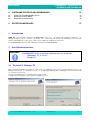
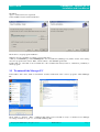
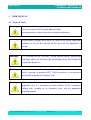
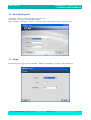
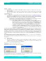
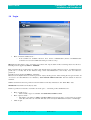
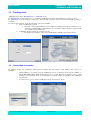
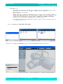
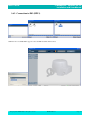
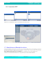
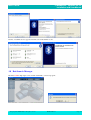
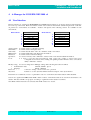
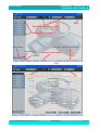
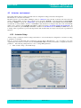
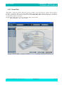
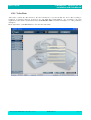
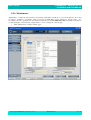
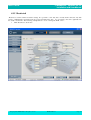
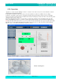
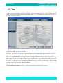

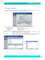
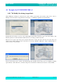
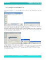
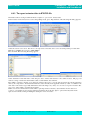
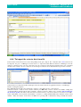
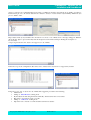
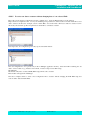
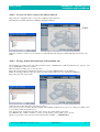
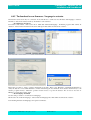
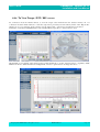
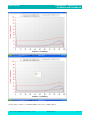
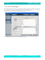
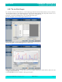
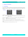
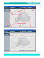
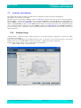
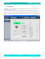
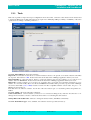
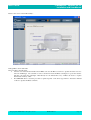
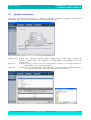

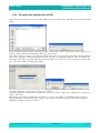
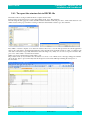
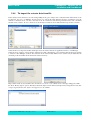
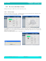
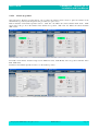
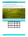
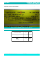

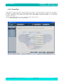
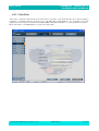
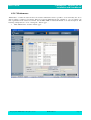
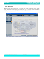
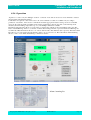
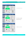

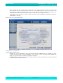
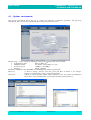
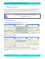
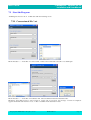
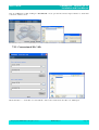
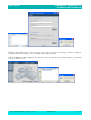


![[User manual] - KX_series_user_EN](http://vs1.manualzilla.com/store/data/005985322_1-73e2348e6003cbf1e0abe0da04f5dcec-150x150.png)