1
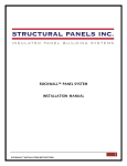
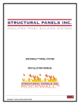
Complete Custom Metal Building Design and Pricing Software
The most advanced
metal building design
and pricing system on
the planet!
IQS Introduction
Ladies and Gentlemen, we have arrived! Welcome to IQS – the most advanced metal building
design and pricing system on the planet! I would like to personally thank you for your interest
in our products and services!
With IQS, the power is in your hands. You are at the command of the world’s first and only “real-time” design
system, giving you the power to create an almost endless array of pre-engineered buildings in seconds. You will not
find another system that gives you the flexibility to create structures for Add-On buildings, Lean-To buildings, Open
Walled, Non-symmetrical shapes, Single Slopes, Gables, Modular
buildings to 150,000 square feet and an almost endless array of
aircraft hangar buildings can be created using IQS – including
modular hangar structures with multiple hangar door openings.
All of this is available to you in a fully-rendered 3D graphical
interface with the power to produce a set of approval drawings,
literally in seconds.
If you’re thinking it sounds too good to be true, we are not
surprised. Not a single company in the pre-engineered building
business has accomplished this feat… until now. An enormous effort
has been made to provide you with this revolutionary system.
Not only do we have plans to continue the further development of
IQS, it is our core focus. As an IQS user, you will have the power
of design, but more importantly you will be able to use business
logic built into the system. What this means to you is that you will
be able to search jobs by customer name, city, zip, phone number or any other customer related data. In today’s fast
paced world you need complete flexibility in your system, and we are bringing it all to you.
Our future plans include a host of enhancements and by late 2008 we should be on track to release a new design
add-on to IQS. This plug-in will allow you to combine projects together, like high-low roof step downs, or combining
2 to 10 different buildings together. It will produce Foundation Plans and specs on-the-fly by December of 2008
– bringing a force of value unmatched in our industry.
Sincerely,
Mark Moore
Founder & Chairman
ICON Building Systems
Table of Contents
IQS Introduction . . . . . . . . . . . . . . . . . . . . . . . . . . . . . . 1
Main Menu
New . . . . . . . . . . . . . . . . . . . . . . . . . . . . . . . . . . . . . . . . . . . . . . . . . . . . . . . . . . . . . . . . 3
Open . . . . . . . . . . . . . . . . . . . . . . . . . . . . . . . . . . . . . . . . . . . . . . . . . . . . . . . . . . . . . . . . 3
Re-Open for Quoting . . . . . . . . . . . . . . . . . . . . . . . . . . . . . . . . . . . . . . . . . . . . . . 3
Quote . . . . . . . . . . . . . . . . . . . . . . . . . . . . . . . . . . . . . . . . . . . . . . . . . . . . . . . . . . . . . . . 4
Search . . . . . . . . . . . . . . . . . . . . . . . . . . . . . . . . . . . . . . . . . . . . . . . . . . . . . . . . . . . . . . 5
Tools . . . . . . . . . . . . . . . . . . . . . . . . . . . . . . . . . . . . . . . . . . . . . . . . . . . . . . . . . . . . . . . . 6
3D View . . . . . . . . . . . . . . . . . . . . . . . . . . . . . . . . . . . . . 7
Elevation . . . . . . . . . . . . . . . . . . . . . . . . . . . . . . . . . . . . 8
Customer . . . . . . . . . . . . . . . . . . . . . . . . . . . . . . . . . . . . 9
Site . . . . . . . . . . . . . . . . . . . . . . . . . . . . . . . . . . . . . . . . . 9
Job . . . . . . . . . . . . . . . . . . . . . . . . . . . . . . . . . . . . . 10-11
Building . . . . . . . . . . . . . . . . . . . . . . . . . . . . . . . . . 12-19
Options . . . . . . . . . . . . . . . . . . . . . . . . . . . . . . . . . 20-21
Walls . . . . . . . . . . . . . . . . . . . . . . . . . . . . . . . . . . . 22-24
Colors . . . . . . . . . . . . . . . . . . . . . . . . . . . . . . . . . . . . . . 25
Accessories . . . . . . . . . . . . . . . . . . . . . . . . . . . . . . . . . 26
Bays & Openings . . . . . . . . . . . . . . . . . . . . . . . . . . 27-29
Sample Approval Drawings . . . . . . . . . . . . . . . . . 30-36
System Requirements . . . . . . . . . . . . . . . . . . . . . . . . . 37
ICON Team Members . . . . . . . . . . . . . . . . . . . . . . . . . 38
Conversion Tables . . . . . . . . . . . . . . . . . . . . . . . . . . . . 39
Note: All prices and measurements reflected in this document are for
sample purposes only and in no way reflect actual costs or measurements.
Main Menu - New
The New menu item opens a new window with a new job with a
default building configuration.
Main Menu - Open
Opens an existing job based on the established job number.
Use the check box to automatically retrieve the latest revision of
the job number entered.
Open an older version on the job number entered by selecting
from the drop down menu.
Main Menu - Re-Open For Quoting
Once a purchase order is created for a job, IQS does not allow further modifications
to the job. This is necessary because the purchase order should reflect the job’s
current state, and if changes are made, the purchase order is no longer up to date.
If changes are necessary, click the Re-open for quoting menu item and the job is
unlocked. Any changes to the job effectively invalidate all prior purchase order
documents for that job. Any revision of a job can be re-opened at any time.
Quote 391644 - 40 x 60 x 14 8:12 - IQS
New
Open
Quote
Re-open for quoting
Search
Tools
Help
3D view
Elevation
20'
20'
12'
12
16'
12'
8.0
14'
14'
Door opening
Window opening
Bay 1:
Bay
width
12.0
elevation
0.0
open
Company
Bay 2:
width
16.0
elevation
0.0
open
Address
Bay 3:
width
12.0
elevation
0.0
open
Find duplicate customer
Zip
78155
County
City
Seguin
Phone 1&2
(
)
-
Cell
(
)
-
State
x
Fax
Guadalupe
Texas
(
)
-
(
)
-
x
E-mail
Lead source Phone
Customer
Distance unit: Imperial
Lead status
Site
Revision: 9
Job
Building
None
Options
Status: Waiting for approval
Walls
Colors
Sales person: Mark Moore
Accessories
Dealer: ICON
2'
4'
Bays & Openings
Name F/L
3'
3'
1' 6"
6' 6"
8'
d5
40'
4'
Customer
d4
d3
6' 6"
3'
3'
d2
1' 6"
2'
d1
Wide opening
Left wall
Main Menu - Quote
Click to generate a price list or to save changes to your currently
open job.
Note: a quote must be run in order to save any changes to your job to
ensure all data related to this job is current
In the quote window, you will have the following selections:
Save - saves the current job with revisions
Create a Purchase Order - generates a multi-page purchase
order document in PDF format for the customer to review and sign,
including approval drawings of the building. Once the purchase
order is created it can still be downloaded later using the
Download purchase order button
Note: Once a PO is created, the job cannot be revised unless it is reopened for quoting. This option will appear in the main menu as an “open
lock” if available to a job. The entire job will not need to be started over.
Print - sends the pricing overview to the printer
Print Preview - Preview the document as it will be printed prior
to actually printing
Quote 391644 - 40 x 60 x 14 8:12 - IQS
New
Open
Quote
Search
Tools
Help
3D view
Elevation
20'
20'
12'
12
16'
12'
8.0
14'
14'
8.0
W
: 12
L
40.0
Hb
60.0
Tapered
Base Cond.
RF Column
Tapered
SW Girt
Bypass
Angle
Insets left
0
Loads
Dead
2.5
Customer
Distance unit: Imperial
Insets right
Live
0
Site
Revision: 9
Job
Bay
14.0
Gable
Interior column editor
Ground Snow
20.0
Hf
14.0
Profile
Fully sheeted
RF Rafter
Building
Collateral
12.0
Options
Status: Waiting for approval
0.5
Walls
Colors
Sales person: Mark Moore
Accessories
Dealer: ICON
2'
3'
3'
1' 6"
6' 6"
8'
4'
Bays & Openings
Roof Pitch
Type
d5
40'
4'
Building
d4
d3
6' 6"
3'
3'
d2
1' 6"
2'
d1
Door opening
Window opening
Bay 1:
width
12.0
elevation
0.0
Wide opening
open
Bay 2:
width
16.0
elevation
0.0
open
Bay 3:
width
12.0
elevation
0.0
open
Left wall
Main Menu - Search
Search for existing jobs using any of the information fields
provided. Go directly to a specific job(s) by entering the
customer’s name, or search all jobs from a certain sales person
from within a designated zip code.
Select from the options retrieved from your
search and open the latest version or a
previously saved revision.
Note: Click on the column headers to organize the
search results in ascending or descending order
(ex: dates modified, city, state, etc.)
Quote 391644 - 40 x 60 x 14 8:12 - IQS
New
Open
Quote
Search
Tools
Help
3D view
Elevation
20'
20'
12'
12
16'
12'
8.0
14'
14'
Wind MPH:
IBC 00
Seismic Coef.
Eng. Pkg.
0.197
90.0
Seismic Zone
Exp.
Bay
B
Measurements system
Imperial
Standard Package (No Cert.) ($0.00)
Foundation plans
Extra Items Price
0.00
Fees discount
0.00
Notes
Customer
Distance unit: Imperial
Site
Revision: 9
Job
Building
Options
Status: Waiting for approval
Walls
Colors
Sales person: Mark Moore
Accessories
Dealer: ICON
2'
4'
Bays & Openings
Code
3'
3'
1' 6"
6' 6"
8'
d5
40'
4'
Job
d4
d3
6' 6"
3'
3'
d2
1' 6"
2'
d1
Door opening
Window opening
Bay 1:
width
12.0
elevation
0.0
Wide opening
open
Bay 2:
width
16.0
elevation
0.0
open
Bay 3:
width
12.0
elevation
0.0
open
Left wall
Main Menu - Tools
Settings - In the settings, the 3D rendering type can be changed.
By default the rendering type is DirectX, which is supported by
most machines.
Alternatively, OpenGL and GDI can be used. GDI rendering
displays the building as a wire frame
Save 3D screenshot - saves a PNG image file of the 3D
rendering as it appears in the 3D view frame of the IQS interface
Note: Save multiple images at different angles to email to clients.
Note: PNG image files utilize RGB color format with a 72 dpi image
resolution.
Print 3D screenshot - sends the 3D rendering to your specified
printer. The rendering prints as it appears in the 3D view frame of
the IQS interface
Note: The dark gray background of the
3D view will be omitted from the actual
printout. Only the building will print.
Sample building rendered using GDI wire frame.
Quote 391644 - 40 x 60 x 14 8:12 - IQS
New
Open
Quote
Search
Tools
Help
Settings
3D view
Elevation
Save 3D screenshot
20'
Print 3D screenshot
20'
12'
Disable internal interface
12
16'
12'
8.0
14'
14'
8.0
W
: 12
L
40.0
Hb
60.0
Tapered
Base Cond.
RF Column
Tapered
SW Girt
Bypass
Angle
Insets left
0
Loads
Dead
2.5
Customer
Distance unit: Imperial
Insets right
Live
0
Site
Revision: 9
Job
Bay
14.0
Gable
Interior column editor
Ground Snow
20.0
Hf
14.0
Profile
Fully sheeted
RF Rafter
Building
Collateral
12.0
Options
Status: Waiting for approval
0.5
Walls
Colors
Sales person: Mark Moore
Accessories
Dealer: ICON
2'
3'
3'
1' 6"
6' 6"
8'
4'
Bays & Openings
Roof Pitch
Type
d5
40'
4'
Building
d4
d3
6' 6"
3'
3'
d2
1' 6"
2'
d1
Door opening
Window opening
Bay 1:
width
12.0
elevation
0.0
Wide opening
open
Bay 2:
width
16.0
elevation
0.0
open
Bay 3:
width
12.0
elevation
0.0
open
Left wall
3D View
Click, hold and drag anywhere within this frame to reposition the 3D rendering.
Rotate the rendering by using the slider arrow directly underneath.
Zoom in and out of the 3D rendering using the scroll-wheel on your mouse.
Note: View a 3D elevation and the corresponding elevation drawing by selecting one of
the four elevation views represented in the lower right corner of the 3D view frame.
Note:
To391644
print or
save
image
Quote
- 40
x 60an
x 14
8:12 -file
IQSof the 3D rendering, select “Tools” from the main menu.
Open
Quote
Search
Tools
3D view
Elevation
14'
3'
d2
1' 6"
3'
2'
d1
4'
Customer
8.0
Roof Pitch
Type
Site
Job
W
: 12
40.0
L
Options
Hb
60.0
Open
Quote
Base Cond.
Insets left
Loads
Dead
Search
Angle
3D view
Insets right
0
Live
2.5
Walls
RF Column
Tools
Help
SW Girt
Colors
Hf
14.0
Profile
Fully sheeted
Rafter
QuoteRF
391644
- 40 x Tapered
60 x 14 8:12 - IQS
New
Building
14.0
Gable
Tapered
Bypass
Ground Snow
20.0
Revision: 9
Door opening
Window opening
Bay 1:
width
12.0
elevation
12.0
Bay 2:
width
16.0
elevation
16.0
Bay 3:
width
12.0
elevation
12.0
Elevation
Interior column editor
0
Bays & Openings
Bay
20'
Collateral
12.0
Status: Waiting for approval
20'
12'
0.5
Sales person: Mark Moore
16'
12'
8.0
12
Distance unit: Imperial
Accessories
Dealer: ICON
14'
14'
Insulation
Liner
Door opening
Window opening
Wall
None
Wall
None
Bay 1:
width
12.0
elevation
0.0
open
Roof
None
Roof
None
Bay 2:
width
16.0
elevation
0.0
open
Bay 3:
width
12.0
elevation
0.0
open
Miscelaneous
Base trim
Sheet notch
Gutter
Cover trim
Customer
Distance unit: Imperial
Site
Revision: 9
Job
Wainscot height
Building
0.197
Options
Status: Waiting for approval
Walls
Colors
Sales person: Mark Moore
Accessories
Dealer: ICON
2'
4'
Bays & Openings
Bay
3'
3'
1' 6"
6' 6"
8'
d5
40'
4'
Options
d4
d3
6' 6"
3'
3'
d2
1' 6"
2'
d1
Wide opening
Left wall
Wide opening
Elevation
Click, hold and drag anywhere within this frame to reposition the
elevation drawing.
Zoom in and out of the elevation drawing using the scroll-wheel
on your mouse.
Note: View an elevation drawing and the corresponding 3D elevation by
selecting one of the four elevation views represented in the lower right
corner of the 3D view frame.
Elevation
14'
d2
40'
4'
rs
Accessories
6' 6"
8'
6' 6"
d3
3'
1' 6"
3'
2'
d1
Bays & Openings
Bay
Door opening
Window opening
Bay 1:
width
12.0
elevation
12.0
Bay 2:
width
16.0
elevation
16.0
Quote 391644
x 14 8:12 -12.0
IQS
Bay 3:- 40 x 60width
elevation
12.0
New
Open
Quote
Search
Tools
Wide opening
Left wall
Help
3D view
Elevation
20'
20'
12'
12
16'
12'
8.0
Dealer: ICON
14'
14'
8.0
W
: 12
L
40.0
Hb
60.0
Tapered
Base Cond.
RF Column
Tapered
SW Girt
Bypass
Angle
Insets left
0
Loads
Dead
2.5
Customer
Distance unit: Imperial
Insets right
Live
0
Site
Revision: 9
Job
Bay
14.0
Gable
Interior column editor
Ground Snow
20.0
Hf
14.0
Profile
Fully sheeted
RF Rafter
Building
Collateral
12.0
Options
Status: Waiting for approval
0.5
Walls
Colors
Sales person: Mark Moore
Accessories
Dealer: ICON
2'
3'
3'
1' 6"
6' 6"
8'
4'
Bays & Openings
Roof Pitch
Type
d5
40'
4'
Building
d4
d3
6' 6"
3'
3'
d2
1' 6"
2'
d1
Door opening
Window opening
Bay 1:
width
12.0
elevation
0.0
Wide opening
open
Bay 2:
width
16.0
elevation
0.0
open
Bay 3:
width
12.0
elevation
0.0
open
Left wall
Customer
Input all relevant customer information in this window. If this project
pertains to an existing customer, select “Find Duplicate Customer” to
import the contact information from a previous or existing job.
Entering the zip code will automatically populate the City, State and
County fields. Also
the- building
code,
seismic zone, seismic coefficient,
Quote 391644
40 x 60 x 14 8:12
- IQS
wind speed and ground snow load are set based on the zip code. These
can be found in the job and building tabs.
Open
Quote
Search
Tools
3D view
Elevation
20'
To quote a job, at least the zip code and lead source have to be filled in.
20'
12'
12
16'
12'
8.0
Site
14'
14'
Site
Job
Building
Options
Walls
Colors
Accessories
Address:
Zip:
78155
County:
City:
Seguin
Guadalupe
State:
Texas
Fax:
(
Door opening
Window opening
Bay 1:
width
12.0
elevation
12.0
Bay 2:
width
16.0
elevation
16.0
Bay 3:
width
12.0
elevation
12.0
(
)
-
x
Distance unit: Imperial
Revision: 9
)
-
Status: Waiting for approval
Sales person: Mark Moore
Dealer: ICON
Quote 391644 - 40 x 60 x 14 8:12 - IQS
New
Open
Quote
Search
Tools
Help
3D view
Elevation
20'
20'
12'
12
16'
12'
8.0
14'
14'
40'
4'
Door opening
Window opening
Bay 1:
Bay
width
12.0
elevation
0.0
open
Company
Bay 2:
width
16.0
elevation
0.0
open
Address
Bay 3:
width
12.0
elevation
0.0
open
Find duplicate customer
Zip
78155
County
City
Seguin
Phone 1&2
(
)
-
Cell
(
)
-
State
x
Fax
Guadalupe
Texas
(
)
-
(
)
-
x
E-mail
Lead source Phone
Customer
Distance unit: Imperial
Lead status
Site
Revision: 9
Job
Building
None
Options
Status: Waiting for approval
Walls
Colors
Sales person: Mark Moore
Accessories
Dealer: ICON
2'
4'
Bays & Openings
Name F/L
3'
d5
1' 6"
6' 6"
8'
3'
d4
d3
6' 6"
3'
3'
d2
1' 6"
2'
d1
Customer
Wide opening
Left wall
2'
3'
3'
Left wall
Wide opening
Contact F/L:
Phone:
1' 6"
6' 6"
8'
4'
Bays & Openings
Bay
Project:
Use customer data
d5
40'
4'
Customer
d4
d3
6' 6"
3'
d2
1' 6"
2'
d1
3'
Select “Use Customer Data” to apply the same information from
the Customer Tab to the Site Tab. If the job site information is
different, input all relevant data in this window.
Job
Much of this data will be automatically populated based on the Site information provided. The
Measurement system by default is “Imperial”, which is standard for continental U.S. measurements.
Building Code
Building codes are intended to provide for the safe use of buildings and structures under “normal”
conditions. The code describes exactly how each part of the building should be loaded and designed.
These loads are based on Snow load, Wind Speed, Seismic Coefficient (earthquake), Collateral load
and Exposure. These loads will be applied in various “Design Combination” to determine the most
critical loading. From these combinations all member sizes and spacing will be determined.
IQS determines the building code based on the job site’s
zip code. The most common building code is IBC.
For a more detailed explanation of building codes see
topic Building Codes Explained.
Wind Speed
As wind blows it places pressure and suction on the
building surfaced. The exact pressure/load is based not
only on the formulas and tables contained in the specific
building code chosen, but also the size and shape of
your building. By entering the Wind Speed, IQS designs
the optimum structural member sizes and their spacing.
Wind Exposure
The characteristics of ground surface irregularities
(natural topography and vegetation as well as
constructed features) for the site at which the building is to be constructed.
Quote 391644 - 40 x 60 x 14 8:12 - IQS
New
Open
Quote
Search
Tools
Help
3D view
Elevation
20'
20'
12'
12
16'
12'
8.0
14'
14'
Wind MPH:
IBC 00
Seismic Coef.
Eng. Pkg.
0.197
90.0
Seismic Zone
Exp.
Bay
B
Measurements system
Imperial
Standard Package (No Cert.) ($0.00)
Foundation plans
Extra Items Price
0.00
Fees discount
0.00
Notes
Customer
Distance unit: Imperial
Site
Revision: 9
Job
Building
Options
Status: Waiting for approval
Walls
Colors
Sales person: Mark Moore
Accessories
Dealer: ICON
10
2'
4'
Bays & Openings
Code
3'
3'
1' 6"
6' 6"
8'
d5
40'
4'
Job
d4
d3
6' 6"
3'
3'
d2
1' 6"
2'
d1
Door opening
Window opening
Bay 1:
width
12.0
elevation
0.0
Wide opening
open
Bay 2:
width
16.0
elevation
0.0
open
Bay 3:
width
12.0
elevation
0.0
open
Left wall
Job
Wind Exposure (cont.)
Exposure A: Large city centers with at least 50% of the buildings having a height in excess of 70 feet.
Exposure B: Urban and suburban areas, wooded areas, or other terrain with numerous closely spaced
obstructions having the size of single-family dwellings or larger.
Exposure C: Open terrain with scattered obstructions.
Exposure D: Flat, unobstructed areas exposed to wind flowing over open water (excluding shorelines
in hurricane prone regions) for a distance of at least 1 mile.
Seismic Coefficient
This is the influence of earthquake activity on your steel building. The higher this number the more
influence seismic has or the greater the seismic loading. Some building codes such as the Uniform
Building Code (UBC) or the California Building Code (CBC) also use seismic zone. These also influence
seismic design; Zone 0 having the least influence and Zone 4 having the greatest.
Seismic Zone / Site Classification
The seismic zone/site classification is a gauge of your soil’s capacity to transmit activity from the
lower soil to the upper surface. Usually this data is provided by a local Geotechnical Engineer or the
Local Project Engineer. If site soil conditions are not identified to establish the site class, IBC allows
you to use site class “D”. Zone/Site Classification as follows:
Soil Description
• A = Hard Rock
• B = Rock
• C = Very dense soil and hard rock
• D = Stiff Soil
• E = Soft Soil
• F = Weak Soil
“E” and “F” are unique soil conditions and require special design considerations, which may result
in increased engineering design and/or foundation cost. Contact a local Professional Engineer for
foundation requirements and soil testing.
Engineering Package
You should determine if your building requires certified/stamped drawings and/or design
calculations from a registered structural engineer licensed in your state. Please contact your local
building official for this information prior to ordering a building.
Load Reduction Allowed
Determine the correct roof live load, if your local code stipulates that load reduction is not allowed
un-check the “Load Reduction Allowed” checkbox.
Foundation Plans
Check this if you are required to have Engineer Stamped plans to satisfy your local permit office, or if
you prefer to build your foundation according to specified plans.
Notes to Customer
A place to input Additional Notes about the job is available here.
11
Building
Enter all data relating to size, dimension and overall building information.
Width - Overall width of the building
Length - Overall length of the building
Hb - Eave height to the back of the building
Hf - Eave height to the front of the building
Type - Roof only to remain open, Roof only to be enclosed, Partially sheeted to remain open,
Partially sheeted to be enclosed
Interior Column Editor - See pgs. 18-19
Loads
Dead - The dead load is the weight of the building itself, and is comprised of the roof panels,
trim, mastic, screws, purlins, eave struts, bolts and the structural frame.
Live - The roof live loads are produced (1) during maintenance by workers, equipment, and
materials, and (2) during the life of the structure by movable objects such as planters and by
people, but do not include wind, snow, seismic or dead loads. A clear distinction is made
between “live” and “snow” loads. It is important that these two loads be treated separately
because the probabilities of occurrence for snow loads are very different from those for roof
live loads. Roof live load defined by the model codes is a reducible 20 pounds per square foot.
Ground Snow - In the northern US, design of a building to withstand snow loading is critical.
Snow loading is dependent on several factors. These factors include roof slope, if the structure
is heated, if the structure is insulated, if the roof slope is slippery or if it contains high friction
that will “hold” the snow on the roof.
Collateral - Collateral loads are additional dead loads hung from the building, such as
sprinkler systems; drop ceilings, HVAC equipment, lighting etc.
Quote 391644 - 40 x 60 x 14 8:12 - IQS
New
Open
Quote
Search
Tools
Help
3D view
Elevation
20'
20'
12'
12
16'
12'
8.0
14'
14'
8.0
W
: 12
L
40.0
Hb
60.0
Tapered
Base Cond.
RF Column
Tapered
SW Girt
Bypass
Angle
Insets left
0
Loads
Dead
2.5
Customer
Distance unit: Imperial
Insets right
Live
0
Site
Revision: 9
Job
Bay
14.0
Gable
Interior column editor
Ground Snow
20.0
Hf
14.0
Profile
Fully sheeted
RF Rafter
Building
Collateral
12.0
Options
Status: Waiting for approval
0.5
Walls
Colors
Sales person: Mark Moore
Accessories
Dealer: ICON
12
2'
3'
3'
1' 6"
6' 6"
8'
4'
Bays & Openings
Roof Pitch
Type
d5
40'
4'
Building
d4
d3
6' 6"
3'
3'
d2
1' 6"
2'
d1
Door opening
Window opening
Bay 1:
width
12.0
elevation
0.0
Wide opening
open
Bay 2:
width
16.0
elevation
0.0
open
Bay 3:
width
12.0
elevation
0.0
open
Left wall
Building
(continued)
Roof Pitch Profiles
IQS allow users to set a roof pitch value infinitely between 0.5:12 and 8:12
(provided the eave limits are not exceeded) IQS constrains the wall heights.
Note: Currently wall heights up to 30 feet are supported.
1:12 Roof Pitch
2:12 Roof Pitch
3:12 Roof Pitch
4:12 Roof Pitch
5:12 Roof Pitch
6:12 Roof Pitch
7:12 Roof Pitch
8:12 Roof Pitch
13
Building
Sheeting Condition
Choices are:
• Fully sheeted (default).
• Roof only to remain open
• Roof only to be enclosed
• Partially sheeted to remain open
• Partially sheeted to be enclosed
Choose the proper building sheeting condition.
“Enclosed” means the building is completely enclosed
in some material. That material can vary from sheets,
masonry, or even another enclosed building. “Partially
Enclosed” means either the building is completely open
to a given elevation, or that part of the building is open
and part is enclosed. “Open” means that the building is
completely open to remain open.
Illustration of Roof Only To Remain Open
Back Eave Height
Eave height to the back of the building.
Front Eave Height
Eave height to the front of the building.
Inset
Defines the number of inset roof bays. At least one bay
must remain not being inset.
Asymmetrical Frame Profile Demonstrates Different
Front and Back Eave Heights
Elevation Drawing of an Inset
3D Rendering
of an Inset
20'
20'
20'
60'
14
20'
20'
20'
24'
Building
(continued)
Rigid Frame Types
Rafters
Choices are tapered and straight (tapered is
default). Choosing a straight rafter over a tapered is
typically to achieve a particular design style. There
is little to no benefit of having a straight (constant
depth) over tapered outside of architectural design
considerations. Buildings utilizing constant depth
rafter members usually have the rafters exposed
and are a part of a design finish and allow a more
consistent look throughout the roof system.
Straight Rafter, Straight Column
Constant depth rafters are usually more costly than
tapered.
Columns
Column types are straight and tapered (tapered is
default). Some projects may require the use of
straight columns for a particular finish result.
Tapered columns are the industry standard and are
usually the optimum choice, and less costly than
straight columns. The larger the building is the more
economical tapered members become.
Tapered Rafter, Tapered Column
Large spans utilizing straight rafters will be more
costly than with tapered members.
Straight Rafter, Tapered Column
Tapered Rafter, Straight Column
15
Building
(continued)
Rigid Frame Profiles
The following profiles are supported:
• Gable (default): This is a symmetrical building with equal eave heights and the peak in the center of the end
wall. This the most common type of frame profile.
• Single slope: Here the peak or high point of the building is at one end. Side wall eave heights will not be at
the same height.
• Asymmetrical: This building either has sidewalls that are not the same height or a peak that is not in the
center of the end wall or both.
• Lean-to: the building is a single slope building that will be attached to a large building. It will be connected
on its front side.
Multi-surface roofs are available via special quote.
Note: Future plans for IQS development include Gambrel and Raised Center Aisle Buildings.
Single Slope Frame Profile
Lean-To Frame Profile
Asymmetrical Frame Profile
Double Slope (Gable) Frame Profile
16
Building
(continued)
Base Conditions
Currently IQS provides 3 framing conditions, standard angle, base channel and base girt. Every
metal building has some type of base connection along the building perimeter, allowing the
connection of sheeting. This “base condition” determines exactly how the panels connect to the
foundation. To prevent water and pests from entering the building at the base, panels extend below
the finished floor of the building.
Base girt elevation default is 6 inches above grade.
Note: For partial wall conditions the default member is CEE. Base Condition - Angle (default)
Base Condition - Channel
Base Condition - Girt
Note: Illustrations are shown with optional base trim and NO concrete
notch in the foundation.
Side Wall Girt
Bypass sidewall girts are the most economical choice. However, applications
require more clearance between columns. Choosing flush sidewall girts will
inset the rigid frame into the girt cavity, thus creating a slightly larger clearance
between the rigid frames. Many schools and retail applications utilize flush
sidewall systems.
Flush
Bypass
17
Building
(continued)
Interior column editor
When the building width is 165’ or higher, then the frames need to be supported by interior columns.
The building is then referred to as a so-called modular building, whereas without interior columns it
would be a clear span building. IQS warns the user when interior columns are not defined while they
should be. Press the Interior column editor link in the Building tab to pop up the Frames editor dialog.
IQS allows 4 different frames to be defined. By default only one frame is defined. To add a frame,
press the Add frame button in the top menu.
Each frame can have its own column spacing settings. To change the column spacing for a frame,
press the Edit button for that frame, and the Frame Editor dialog will pop up.
A frame can be assigned to a frame line. A frame line is a physical frame in the building, whereas a
frame is a template for a frame line. To assign a frame to one or more frame lines, take the following
steps:
• Select the frame you want to assign in the Frames list.
• Select the frame lines you want to assign the selected frame to in the bottom list. Multiple frame
lines can be selected simultaneously by holding the Ctrl key while mouse clicking on a row to
toggle a single frame line, or by holding the Shift key while mouse clicking on a row to select a
range.
• Click the Assign selected frame to selected frame lines button in the top menu
An example of a 150 ft wide clear span building
An example of a 200 ft wide modular building (with 2 interior columns per frame line)
18
Building
(continued)
Interior column editor
The frame editor allows the user to define interior column spacings for a frame. It allows two ways of
defining these spacings:
• Equally spacing columns by specifying the number of interior columns. This is the easiest way, since
the real column spacings will change automatically as the building width changes while designing
the building. Click the Equally spaced columns radio button to use this type of spacing.
• If the user chooses the User defined column spacing option, then he can specify exactly where the
interior columns need to be placed. In the example below the spacings are 60’ and 70’, meaning
that they are placed 60’ and 130’ from the back wall.
19
Options
Select additional options for your building including wall and roof insulation thickness as well as full
or 8 foot lining. Other options available include:
Insulation
The metal building is rapidly becoming more popular for a variety of reasons. They can be built very
quickly and are extremely low in cost. They can easily adapt to any number of external architectural
treatments without restricting their interior floor planning. A primary reason for this flexibility is the
development of insulation specifically designed for metal buildings. The development of advanced
insulation systems with more efficient thermal performance is so advanced that it has enabled metal
buildings everywhere to evolve into many of the showrooms, retail outlets, schools, offices and
shopping centers we see today.
Today’s high-energy costs have made insulation a critical consideration during any construction
planning. An insulation system that is properly selected and professionally installed will return more
on its investment than any other building component. Insulation provides many benefits:
• Improved appearance
• Greater comfort
• Substantial reductions in fuel and electricity costs
• Condensation and noise control
• Reduction of the amount of investment dollars and space needed for heating and cooling equipment.
INSULATION WILL RETURN MORE ON ITS INVESTMENT THAN ANY OTHER
BUILDING COMPONENT. Note: when insulation is added to a building, it is shipped separately and extra shipping costs are involved.
IQS allows choosing the wall and roof insulation independently:
Quote 391644 - 40 x 60 x 14 8:12 - IQS
New
Open
Quote
Search
Tools
Help
3D view
Elevation
20'
20'
12'
12
16'
12'
8.0
14'
14'
Insulation
Liner
Door opening
Window opening
Wall
None
Wall
None
Bay 1:
width
12.0
elevation
0.0
open
Roof
None
Roof
None
Bay 2:
width
16.0
elevation
0.0
open
Bay 3:
width
12.0
elevation
0.0
open
Miscelaneous
Base trim
Sheet notch
Gutter
Cover trim
Customer
Distance unit: Imperial
Site
Revision: 9
Job
Wainscot height
Building
0.197
Options
Status: Waiting for approval
Walls
Colors
Sales person: Mark Moore
Accessories
Dealer: ICON
20
2'
4'
Bays & Openings
Bay
3'
3'
1' 6"
6' 6"
8'
d5
40'
4'
Options
d4
d3
6' 6"
3'
3'
d2
1' 6"
2'
d1
Wide opening
Left wall
Options
(continued)
• Wall: no wall insulation or three, four or six inch of insulation can be
chosen (default is none).
• Roof: no roof insulation or three, four or six inch of insulation can be
chosen (default is none).
Liner
• Wall: choices for wall liner are none, eight foot or full (default is
none).
• Roof: choices for wall liner are none or full (default is none).
Miscellaneous
• Base Trim: specify whether base trim is included (by default not
included).
Gutter
Wainscot Height
Base Trim without Sheet Notch
Base Trim with Sheet Notch
• Gutter: specify whether gutter is included (by default not included).
Gutters and downspouts are an optional accessory that serves as
trim. Gutters dramatically improve the appearance of buildings, and
we recommend them for most building applications. Downspouts
control the water falling from the roof, preventing the water from
splashing up on the sides of the building.
• Sheet Notch: specify whether sheet notch is included (included by
default).
• Cover Trim: specify whether cover trim is included (included by
default). Though common, the red-iron jamb and header around a
door opening are normally exposed. Using jamb cover trim is an
inexpensive way to improve the appearance of your steel building.
Cover Trim - Window
• Wainscot Height: specify the wainscot height (default the building
has no wainscot).
Sheet Metal Thickness Gauges
By default a the sheet metal thickness gauge for wall and roof is 26.
Optionally, the thicker 24 gauge can be chosen.
Sheet Notch
21
Walls
Wall Conditions
The walls tab allows the user to add or modify a host of building features with just a few mouse
clicks. Select from a variety of end wall frame conditions including bearing frame (default), hot-rolled
rafter, non-expandable rigid frame or expandable rigid frame.
A standard box building generally has bearing frame end walls. The bearing frame end wall consists
of vertical columns that support the rafters. This type of end wall is also known as “post and beam” or
non-expandable end wall.
A hot-rolled rafter end wall utilizes a standard wide flange beam (I-beam) section as the rafter; this
allows more headroom above the door. By setting directly on top of the end wall columns, instead
of fastened to the back of the columns as would occur with a cold formed CEE rafter, the hot-rolled
rafter allows for unobstructed clearance from the door header to the underside of the roof purlins. Note: If a lean-to building is attaching to the building we require a minimum of hot-rolled rafter for end wall
frame that will have attaching lean-to building(s). We will NOT design a lean-to building using a cold-formed
rafter (standard bearing frame).
A non-expandable rigid frame is normally used when large or multiple doors or windows are placed
in an end wall. IQS calculates the capacity of the end wall frame types and designs the appropriate
end wall frame type required. If there are specific requirements that you desire you may input them,
but please remember that if IQS detects that the end wall condition fails structurally, the program
will automatically design an end wall to ensure proper design. Roof only buildings will have a nonexpandable rigid frame unless the user specifies fully loaded. We suggest using a non-expandable
rigid frame if there is a lean-to building attaching at the corner of the side/end wall.
An expandable rigid frame is used primarily when future expansion is desired. All hangar door
buildings are designed utilizing a properly loaded rigid frame. In the case of the hangar door, the
rigid frame is not considered expandable unless the hangar door system is removed, allowing the
building to be expanded.
Quote 391644 - 40 x 60 x 14 8:12 - IQS
New
Open
Quote
Search
Tools
Help
3D view
Elevation
20'
20'
12'
12
16'
12'
8.0
14'
14'
Roof
extensions
Wall Conditions
Left
Bearing Frame
Right
Bearing Frame
Wall
Open?
4.0
4.0
Roof
extensions
Bracing Type
Open?
Options
Bay
Door opening
Window opening
...
Bay 1:
width
12.0
elevation
0.0
open
...
Bay 2:
width
16.0
elevation
0.0
open
Options
Bay 3:
width
12.0
elevation
0.0
open
Front
Panel Shear
4.0
...
Back
Panel Shear
4.0
...
Roof purlins
Peak space
Automatic spacing
1.64
Spacing
4.00
Miscelaneous
Include soffit
Customer
Distance unit: Imperial
Site
Revision: 9
Job
Building
Options
Status: Waiting for approval
Walls
Colors
Sales person: Mark Moore
Accessories
Dealer: ICON
22
2'
4'
Bays & Openings
Wall
3'
3'
1' 6"
6' 6"
8'
d5
40'
4'
Walls
d4
d3
6' 6"
3'
3'
d2
1' 6"
2'
d1
Wide opening
Left wall
Walls
(continued)
Roof Extension
Users can add side wall and gable roof extensions to one or all sides of a building
by mouse clicking or entering the desired size in the “Roof Extension” box. Sizes
can vary per wall and soffit can be excluded by un-checking the “Include Soffit”
checkbox.
Note: Buildings have no roof extension by default. If desired, they will need to be added. The
sample building below has 4 foot roof extensions on all sides. Maximum extensions are 8 ft
for left and right end wall, and 5 ft for front and back sidewall.
The “Open” feature allows for complete
removal of any
wall of the building. If the wall is to remain
open permanently you must select “Partially
Sheeted To Remain Open” under the “Type”
option of the Building tab. If the wall is
designed to be enclosed “By Others” IQS
assumes that the wall system will be self
supporting and NO lateral support of the wall
is allowed. If the wall system being added by
others requires lateral support please contact
your salesperson for a special quote.
Note: Future plans for IQS will allow the user to
design a Spandrel Beam that will carry the entire
or partial wall load.
Options
Users can use the option button to specify girt specific individual girt locations in all walls. When specifying
one or more girt locations IQS will consider the specified
locations as part of the design and optimize the balance
of required framing members. Users can specify an
Interval distance of girt spacing for use with alternate wall
materials. Front and Back side wall eave extensions can be
added per bay by clicking the Options button, otherwise
the entire wall can be specified to have eave extensions by
changing the dimensions in the Roof Extension box.
23
Walls
(continued)
Bracing Type
Select from bracing types including Panel Shear (default), Diagonal Bracing, Wind Column or Portal
Framing. Users can specify the type of bracing desired, or the minimum they desire. However if IQS
detects there is not sufficient bracing, the program will add bracing to satisfy the requirement.
Example, if a user specifies cable bracing, and there is not a sufficient number of bays that can be braced the
program will attempt to place any number of combinations of bracing until the bracing requirement is met. If a
user chooses diagonal bracing and a door opening is placed in every side wall bay the program will attempt
to use one or more portal frames. In the event there is not enough room above the doors to ensure proper
headroom clearance, the program will utilize one or more wind columns to meet the bracing requirement.
End wall bracing is seldom used. There
are many reasons IQS will not design
using diagonal bracing in an end wall.
Slots are required in the secondary
framing to allow for diagonal bracing,
thus weakening the girts and it is our
interpretation that the end wall typically
suffers the most from wind loading,
and we do not use diagonal bracing in
end walls with a flush girt condition. If
IQS detects that there is not sufficient
available panel shear, the program will
select the minimum sized Rigid Frame to
satisfy the design requirement.
Roof Purlins
IQS will design the roof system (secondary framing) in the most optimized manner. Roof Purlins are
automatically sized and spaced; however, they can be manually spaced as necessary. If alternate
roofing material is desired, i.e. shingles over plywood, then select the required spacing and add the
material weight to the Dead Load on the Building Tab.
Note: Peak spacing should be set to a minimum distance if wood sheeting is used for the roof material.
To remove Roof Panels check Remove Sheeting on the under the Sheeting heading. To specify a
specific panel shear capacity for materials supplied by others please contact your salesperson.
Miscellaneous
Options available are to include the soffit; the exterior panel applied to the underside of roof
24
Colors
Our online system includes both Galvalume Plus® and SMP
Colors. For a small price increase you can add a colored roof. Our
standard colored panels consist of a Galvalume® sheet that has
been primed and coated with Silicon Modified Polyester (SMP)
paint.
Hawaiian Blue
Charcoal Gray
Fern Green
Light Stone
Ash Gray
Polar White
Colony Green
Desert Sand
Saddle Tan
Rustic Red
Burnished Slate
Galvalume
Both panel types of panel are very tough, and both our Galvalume
Plus® warranty and our paint warranty run for 25 and 30 years
respectively. The Galvalume Plus® panels cost less, but the
painted panels give your steel building a more refined look.
Actual Colors May Vary Slightly From Printed Samples.
Additional Colors Available.
Quote 391644 - 40 x 60 x 14 8:12 - IQS
New
Open
Quote
Search
Tools
Help
3D view
Elevation
20'
20'
12'
12
16'
12'
8.0
14'
14'
Roof color
Bay
Wall color
Roof trim color
Wainscot color
Wainscot trim color
Primary frames color
Customer
Cover trim color
galvanized
Site
Revision: 9
Job
Gutters color
Secondary frames color
Building
Options
Status: Waiting for approval
galvanized
Walls
Colors
Sales person: Mark Moore
Accessories
Dealer: ICON
25
2'
3'
3'
1' 6"
6' 6"
8'
4'
Bays & Openings
Corner trim color
Distance unit: Imperial
d5
40'
4'
Colors
d4
d3
6' 6"
3'
3'
d2
1' 6"
2'
d1
Door opening
Window opening
Bay 1:
width
12.0
elevation
0.0
Wide opening
open
Bay 2:
width
16.0
elevation
0.0
open
Bay 3:
width
12.0
elevation
0.0
open
Left wall
Accessories
Choose from a wide array of doors, windows and other
accessories for your building. Click the green “plus sign” to
add accessories or the red “X” to remove previously selected
accessories.
Prices displayed will vary depending on proposed building
location, shipping charges and initial sizes of door and window
openings.
Note: All prices will vary depending on individual Dealer mark-up and
location based on Zip Code.
Adding an Accessory
By clicking the + button in the menu a dialog pops up offering a
choice of accessories.
Multiple accessories can be added simultaneously.
Quote 391644 - 40 x 60 x 14 8:12 - IQS
New
Open
Quote
Search
Tools
Help
3D view
Elevation
20'
20'
12'
12
16'
12'
8.0
14'
14'
Bay
Customer
Quantity
Site
Revision: 9
Job
Building
Piece Price
Options
Status: Waiting for approval
Walls
Colors
Sales person: Mark Moore
Accessories
Dealer: ICON
26
2'
3'
3'
1' 6"
6' 6"
8'
4'
Bays & Openings
Description
Distance unit: Imperial
d5
40'
4'
Accessories
d4
d3
6' 6"
3'
3'
d2
1' 6"
2'
d1
Door opening
Window opening
Bay 1:
width
12.0
elevation
0.0
Wide opening
open
Bay 2:
width
16.0
elevation
0.0
open
Bay 3:
width
12.0
elevation
0.0
open
Left wall
Bays & Openings
By default the IQS Software will break up the span of the building
into Bays (ex: a 60 ft. building will have three 20 ft. bays). The
default bay spacing will usually be optimized, please keep end
wall bays to a maximum of 20 feet. Creating end wall bays larger
than 20 feet can result in improper design. Please contact your
salesperson if you require end wall bays over 20 feet wide.
Select a Bay to edit by clicking on the blue label. The Bay will
become highlighted with a gray box. To adjust the size of the Bay,
use the arrows or key in the requested dimensions. The elevation
measurement of a Bay allows for a permanent opening within that
bay area.
Note: Bay elevation must be set to “0” for the addition of doors and
windows.
To add a Bay, click the green “plus sign” next to the word “Bay”
located in the blue bar directly above the Bay measurements.
To add a door or window opening, first
select the Bay for which the opening will
be applied. The opening information will
appear below the selected bay. Here
you can select the type of door to be
installed; type of opening required
and edit the opening dimensions.
Quote 391644 - 40 x 60 x 14 8:12 - IQS
New
Open
Quote
Search
Tools
Help
3D view
Elevation
20'
20'
12'
12
16'
12'
8.0
14'
14'
8.0
W
: 12
L
40.0
Hb
60.0
Tapered
Base Cond.
RF Column
Tapered
SW Girt
Bypass
Angle
Insets left
0
Loads
Dead
2.5
Customer
Distance unit: Imperial
Insets right
Live
0
Site
Revision: 9
Job
Bay
14.0
Gable
Interior column editor
Ground Snow
20.0
Hf
14.0
Profile
Fully sheeted
RF Rafter
Building
Collateral
12.0
Options
Status: Waiting for approval
0.5
Walls
Colors
Sales person: Mark Moore
Accessories
Dealer: ICON
27
2'
3'
3'
1' 6"
6' 6"
8'
4'
Bays & Openings
Roof Pitch
Type
d5
40'
4'
Building
d4
d3
6' 6"
3'
3'
d2
1' 6"
2'
d1
Door opening
Window opening
Bay 1:
width
12.0
elevation
0.0
Wide opening
open
Bay 2:
width
16.0
elevation
0.0
open
Bay 3:
width
12.0
elevation
0.0
open
Left wall
Bays & Openings
(continued)
Door Type (Door Opening)
Currently there are 3 choices:
1. NONE: No door type is considered
2.ROLL-UP: Standard Roll-Up Door specifications are
considered.
3.SECTIONAL: Standard Sectional Door
specifications are considered.
Note: IQS typically designs around common headroom
constraints per door type. If you are unsure about
your headroom requirements please check with your
salesperson or consult the door manufacturer and
headroom requirements.
Opening Type (Door Opening)
Currently there are 4 choices:
1. FACTORY LOCATE: Choose this option when
you are sure of the framed openings location in the
building. Selecting this will result in the door frame
being designed into the wall chosen. All secondary
framing (i.e. wall girts) will be cut to fit the opening.
Installing the door frame with this selection will be
much easier than a field located door.
2.FIELD LOCATE: Choose this option when you are
unsure of the exact door location. This option will
require the cutting of secondary framing members.
Please note that you must never remove a column to place a door.
!!! -REMOVING A COLUMN MAY RESULT IN A
DANGEROUS SITUATION. PLEASE CONSULT THE
MANUFACTURER PRIOR TO REMOVING A COLUMN OR
VERTICAL FRAMING MEMBER. -!!!
3.SHEETED FOR FUTURE USE: Use this option when you would like
the option of having a factory located framed opening in your
building, but are not currently ready for its installation. Girts and
sheeting will be provided to completely cover the opening.
Note: trim will not normally come with this option.
4.INCLUDE SHEETING (no girts): Use this option when you require
additional sheeting for a door that is to be built by others utilizing
the same wall panel material.
Note: Please confirm that the area of the actual opening will be sufficient
to cover the door. If the door is oversized there will not be enough
material to cover.
Offset
You can specify the location of the door by changing the offset
location in the offset control.
28
Bays & Openings
(continued)
Width (Applies to all)
You are able to specify the door width by adjusting the dimension in the WIDTH tab. Though it is not
recommended, IQS will allow columns to be used for door jambs in the event the bay spacing is set
properly to allow this. Normally a door can be placed in a bay and take up the entire width of that
bay. Adjacent bays will have a minimum of 1 foot offset from the door edge. End wall corner columns
will have 2 foot minimum edge clearance. See OFFSET for more details on end wall corner minimum
spacing.
Top (Applies to all)
You are able to specify the door or window height by adjusting the TOP dimension.
Constraints are place on framed openings to accommodate most door types.
Currently IQS requires a 2 foot minimum distance ABOVE the door. This
distance is calculated to the nearest roof edge on sidewalls and to
the underside of roof purlins on end walls. Normally slide doors
located on end walls are no higher than the side wall eave
height unless there is sufficient space to accommodate a
horizontal path wide enough to create clearance to the
nearest roof line. Note: please call your sales rep if
you are unsure about slide door requirements.
Sill (Window)
You are able to specify the sill height of a window
opening by adjusting the dimension in the SILL tab.
Note: adjusting the sill height will not adjust the TOP
height.
Wide Opening (Large Door)
To place a wide opening in an END WALL (only) you must first adjust the end wall bay spacing to
accommodate the door opening. Multiple wide openings can exist in each end wall, however we
typically suggest a maximum of 3 wide openings per end wall with a collective opening width (per
wall) of no more than 180 feet.
We will use a single opening for our example of properly placing a wide opening in the end wall of a
building. We will use a 60 foot wide building with a 50 foot wide (hangar) opening. There are 3 bays
by default, therefore there is no need to remove any bays. If there were more than 3 bays, we would
delete all but 3 for this example.
FIRST we set the bays to (bay 1) 10 feet, 50 feet (bay 2) and 10 feet (bay 3) from left to right.
SECOND we then highlight BAY 2 and mouse click the wide opening button. The wide opening fills
the entire bay. The wide opening will always fill the bay selected
unless there are adjacent doors restricting or
enforcing an offset.
THIRD Select the Wide Opening DOOR
TYPE and adjust any accompanying
requirements to suit your specific needs.
All end wall doors (including wide
openings) are restricted to default
clearances. If your application requires
a lesser clearance, you may need to get
a special quotation.
29
30
DATE:
CUST.#:
JOB NUM.:
Texas
78155
STATE:
ZIP:
14'
8.0 : 12
EAVE HEIGHT, FRONT S.W:
ROOF SLOPE:
Fully sheeted
1
0.197
BLDG CAT:
IMP. FACTOR, SEISMIC :
SEISMIC COEFFICIENT:
DOWNS
RAKE
EAVE
CORNER
ACCESS.
IF SHOWN
IF SHOWN
IF SHOWN
IF SHOWN
IF SHOWN
26 GA.
26 GA.
26 GA.
26 GA.
26 GA.
GUTTER
IF SHOWN
26 GA.
TRIM
WALL
See quote
26 GA
ROOF
26 GA. See quote
SIDEWALL ELEVATION - BACK
ENDWALL ELEVATION - LEFT
ENDWALL ELEVATION - RIGHT
FLOOR PLAN
Machine Bolts & Nuts
HS Bolts 1" & Less
HS Bolts >1" to 1-1/2"
Anchor Bolts (if supplied)
Hot rolled Steel Shapes
Steel Pipes
Structural Tubing
Structural Web Plate
Structural Flange Plates
Cold Form Light Gauge
Roof and Wall Sheets
Cable Brace
Rod Brace
Mill Sections
MATERIALS
A307
A325 - Type 1
A325 - Type 1
A36/A307/F1554
A572
A500
A500
A572/A1011
A529/A572
A653/A1011
A792/A653
A475 - Type 1
A36
A36
ASTM DESIGNATION
FABRICATION NOTES
D-
E2
E1
S2
DRAWING INDEX
CS-1
COVER SHEET
N1
GENERAL NOTES
S1
SIDEWALL ELEVATION - FRONT
MIN. YIELD
Fu = 60 KSI
Fu = 120 KSI
Fu = 105 KSI
Fu = 60 KSI
MIN. TENSILE
Fy = 50 KSI
Fy = 42 KSI
Fy = 46 KSI
Fy = 50 KSI
Fy = 55 KSI
Fy = 50, 55 KSI
Fy = 50, 80 KSI
EX High Strength
Fy = 36 KSI
Fy = 36 KSI
SKYLIGHTS
NOTCH
FL-CEE
TRIM
WHITE
COLOR
NONE
SPC TRIM
BASE CONDITION
N/A
DESCRIPTION
WALL-LIGHTS
WHITE
NO.
COLOR NO.
See quote
DESCRIPTION
See quote
See quote
DESCRIPTION
DOORS/WINDOWS
See quote
SIZE
SPECIAL FRAMED OPENINGS
VENTILATORS
BY MFG
WALLS: STD
ROOF: STD
SCREWS:
WALL
BY OTHERS
BLANKET TYPE INSULATION
Check P.O.
See quote
DESCRIPTION
PAINT: RED OXIDE
ROOF
NONE
NO.
26 GA.
26 GA.
R.E.W.
B.S.W.
N/A
Height
MISC. ACCESSORIES
"R"
"R"
"R"
"R"
TYPE
LINER PANELS
N/A
DESCRIPTION
26 GA.
F.S.W.
NO.
26 GA.
THICK
L.E.W.
WALL
PW
PW
PW
PW
COLOR
FIELD LOCATE ITEMS WILL NOT SHOW UP ON
DRAWINGS: PERSONNEL DOORS, WINDOWS, WALL
AND SKY LIGHTS ALONG WITH RIDGE VENTS AND
OTHER ITEMS MAY NOT SHOW UP ON DRAWINGS.
PLEASE CHECK YOUR PURCHASE ORDER FOR
THESE ITEMS.
Fabrication shall be in accordance with MFG's standard
practices and in compliance with the applicable
sections, relating to design requirements and allowable
stresses of the latest edition of the "AWS Structural
Welding Code D 1.1 and D 1.3
NOTES:
PLEASE PUT SAFTEY FIRST! WE HAVE A COMMITMENT TO MANUFACTURE QUALITY BUILDINGS THAT CAN BE SAFELY ERECTED. HOWEVER, THE SAFETY COMMITMENT AND JOB SITE PRACTICES OF THE ERECTOR
ARE BEYOND OUR CONTROL. IT IS STRONGLY RECOMMENDED THAT SAFE WORKING CONDITIONS AND ACCIDENT PREVENTION PRACTICES ARE THE TOP PRIORITY OF ANY JOB SITE. LOCAL, STATE, AND FEDERAL
SAFETY AND HEALTH STANDARDS SHOULD ALWAYS BE FOLLOWED TO HELP INSURE WORKERS SAFETY. MAKE CERTAIN ALL EMPLOYEES KNOW THE SAFEST AND MOST PRODUCTIVE WAY OF ERECTING A
BUILDING. ALL EMPLOYEES SHOULD KNOW EMERGENCY PROCEDURES. DAILY MEETINGS HIGHLIGHTING SAFETY PROCEDURES ARE ALSO RECOMMENDED. THE USE OF HARD HATS, RUBBER SOLE SHOES FOR
ROOF WORK, PROPER EQUIPMENT FOR HANDLING MATERIAL, AND SAFETY NETS WHERE APPLICABLE, ARE RECOMMENDED.
Approval/permit
FAX 830-372-4267
www.metalbuildingdepot.com
888-372-4266
Seguin
TX 78155
4340 I-10 West
DESCRIPTION
See quote
DATE: N/A
REV. NO.: 0
BUILD FROM DRAWINGS MARKED "FOR CONSTRUCTION" ONLY!!!
CK'D BY
THIS BUILDING MEETS OR
EXCEEDS CODE/CLASS: IBC 00
Revision: 11
Page: 1/7
APPROVAL
DRAWING PACKAGE
ICON Building Systems
DWG BY:
ANGLE
NO.
NO.
0
SHEETING
1
SEISMIC ZONE:
12
SNOW LOAD:
IMP. FACTOR, WIND :
20
90
1
COLLATERAL LOAD:
LIVE LOAD:
B
3
ROOF DEAD LOAD:
WIND EXPOSURE:
INCLUDED
FRAME SELF WEIGHT:
WIND SPEED:
IBC 00
BUILDING CODE:
DESIGN LOADS
60'
14'
NOMINAL LENGTH:
40'
EAVE HEIGHT, BACK S.W:
NOMINAL WIDTH:
BUILDING DESCRIPTION:
DESIGN PARAMETERS
CALCULATIONS
CELL:
Guadalupe
COUNTY:
EMAIL:
FAX:
Seguin
JOB ADDR:
CITY:
PHONE:
COMPANY:
391644
CUSTOMER:
31
NORMAL ERECTION OPERATIONS INCLUDE THE CORRECTIONS OF MINOR MISFITS BY
MODERATE AMOUNTS OF REAMING, CHIPPING, WELDING OR CUTTING, AND THE DRAWING
OF ELEMENTS INTO LINE THROUGH THE USE OF DRIFT PINS. ERRORS WHICH CANNOT BE
CORRECTED BY THE FOREGOING MEANS OR WHICH REQUIRE MAJOR CHANGES IN
MEMBER CONFIGURATION ARE TO BE REPORTED IMMEDIATELY TO MFG BY THE
BUYER/END USE CUSTOMER, TO ENABLE WHOEVER IS RESPONSIBLE EITHER TO
CORRECT THE ERROR OR THE APPROVE THE MOST EFFICIENT AND ECONOMIC METHOD
OF CORRECTION TO BE USED BY OTHERS. (SECTION 7 AISC CODE OF STANDARD
PRACTICE, 9TH EDITION) NEITHER THE FABRICATOR NOR THE BUYER/END USE
CUSTOMER WILL CUT, DRILL OR OTHERWISE ALTER HIS WORK, OR THE WORK OF OTHER
TRADES, TO ACCOMMODATE OTHER TRADES, UNLESS SUCH WORK IS CLEARLY
SPECIFIED, THE BUYER/END USE CUSTOMER IS RESPONSIBLE FOR FURNISHING
COMPLETE INFORMATION AS TO MATERIALS, SIZE LOCATION AND NUMBER OF
ALTERATIONS PRIOR TO PREPARATION OF SHOP DRAWINGS. (SECTION 7 AISC CODE OF
STANDARD PRACTICE, 9TH EDITION)
IT IS RECOMMENDED THAT A PROFESSIONAL ENGINEER EXPERIENCED IN THE DESIGN OF
SUCH STRUCTURES DESIGN THE ANCHORAGE AND FOUNDATION OF THE BUILDING.
(SECTION A10 1996 MBMA LOW RISE BUILDING SYSTEMS MANUAL)
UNLESS OTHERWISE PROVIDED IN THE ORDER DOCUMENTS, MFG DOES NOT DESIGN AND
IS NOT RESPONSIBLE FOR THE DESIGN, MATERIAL AND CONSTRUCTION OF THE
FOUNDATION OR FOUNDATION EMBEDMENT. THE END USE CUSTOMER SHOULD ASSURE
HIMSELF THAT ADEQUATE PROVISIONS ARE MADE IN THE FOUNDATION DESIGN FOR
LOADS IMPOSED BY COLUMN REACTIONS OF THE BUILDING, OTHER IMPOSED LOADS, AND
BEARING CAPACITY OF THE SOIL AND OTHER CONDITIONS OF THE BUILDING SITE.
MFG IS RESPONSIBLE FOR THE DESIGN OF THE ANCHOR BOLT TO PERMIT THE TRANSFER
OF FORCES BETWEEN THE BASE PLATE AND THE ANCHOR BOLT IN SHEAR, BEARING AND
TENSION, BUT IS NOT RESPONSIBLE FOR THE TRANSFER OF ANCHOR BOLT FORCES TO
THE CONCRETE OR THE ADEQUACY OF THE ANCHOR BOLT IN RELATION TO THE
CONCRETE.
THE BUYER/END USE CUSTOMER IS RESPONSIBLE FOR SETTING OF ANCHOR BOLTS AND
ERECTION OF STEEL IN ACCORDANCE WITH MFG "FOR CONSTRUCTION" DRAWINGS ONLY.
TEMPORARY SUPPORTS SUCH AS GUYS, BRACES, FALSE WORK, CRIBBING OR OTHER
ELEMENTS REQUIRED FOR THE ERECTION OPERATION SHALL BE DETERMINED
FURNISHED AND INSTALLED BY THE ERECTOR. NO ITEMS SHOULD BE PURCHASED FROM
A PRELIMINARY SET OF DRAWINGS, INCLUDING ANCHOR BOLTS. USE ONLY FINAL "FOR
CONSTRUCTION DRAWINGS" FOR THE USE. (SECTION 7 AISC CODE OF STANDARD
PRACTICE, 9TH EDITION)
IT IS THE RESPONSIBILITY OF THE BUYER/END USE CUSTOMER TO INSURE THAT MFG
PLANS COMPLIES WITH THE APPLICABLE REQUIREMENTS OF ANY GOVERNING BUILDING
AUTHORITIES. THE SUPPLYING OF SEALED ENGINEERING DATA AND DRAWINGS FOR THE
METAL BUILDING SYSTEM DOES NOT IMPLY OR CONSTITUTE AN AGREEMENT THAT MFG
OR ITS DESIGN ENGINEERS ARE ACTING AS THE ENGINEER OF RECORD OR DESIGN
PROFESSIONAL FOR A CONSTRUCTION PROJECT. THESE DRAWINGS ARE SEALED ONLY
TO CERTIFY THE DESIGN OF THE STRUCTURAL COMPONENTS FURNISHED BY MFG.
THE BUYER/END USE CUSTOMER IS RESPONSIBLE FOR OVERALL PROJECT
COORDINATION. ALL INTERFACE, COMPATIBILITY, AND DESIGN CONSIDERATIONS
CONCERNING ANY MATERIALS NOT FURNISHED BY MFG AND MFG STEEL SYSTEMS ARE
TO BE CONSIDERED AND COORDINATED BY THE BUYER/END USE CUSTOMER. SPECIFIC
DESIGN CRITERIA CONCERNING THIS INTERFACE BETWEEN MATERIALS MUST BE
FURNISHED BEFORE RELEASE FOR FABRICATION OR MFG ASSUMPTIONS WILL GOVERN
(SECTION 4 AND COMMENTARY, AISC CODE OF STANDARD PRACTICE 9TH EDITION)
ONCE THE BUYER/END USE CUSTOMER HAS SIGNED MFG APPROVAL PACKAGE THE
PROJECT IS RELEASED FOR FABRICATION, AND CHANGES SHALL BE BILLED TO THE
BUYER/END USE CUSTOMER INCLUDING MATERIAL, ENGINEERING AND OTHER COSTS. AN
ADDITIONAL FEE MAY BE CHARGED IF THE PROJECT MUST BE MOVED FROM THE
FABRICATION AND SHIPPING SCHEDULE.
APPROVAL OF MFG DRAWINGS AND CALCULATIONS INDICATES THAT MFG HAS
CORRECTLY INTERPRETED AND APPLIED THE CONTRACT DOCUMENTS. THIS APPROVAL
CONSTITUTES THE BUYER/END USE CUSTOMER ACCEPTANCE OF THE MFG DESIGN
CONCEPTS, ASSUMPTIONS, AND LOADING. (SECTION 4 AISC CODE AND MBMA 3.3.3)
MFG STANDARD SPECIFICATIONS APPLY UNLESS STIPULATED OTHERWISE IN THE
CONTRACT DOCUMENTS. MFG DESIGN, FABRICATION, QUALITY CRITERIA, STANDARDS,
PRACTICE, METHODS AND TOLERANCES SHALL GOVERN THE WORK WITH ANY OTHER
INTERPRETATIONS TO THE CONTRARY NOTWITHSTANDING. IT IS UNDERSTOOD BY BOTH
PARTIES THAT THE BUYER/END USE CUSTOMER IS RESPONSIBLE FOR CLARIFICATION OF
INCLUSIONS OR EXCLUSIONS FROM THE ARCHITECTURAL PLANS AND/OR
SPECIFICATIONS. IN CASE OF DISCREPANCIES BETWEEN MFG STRUCTURAL STEEL PLANS
AND PLANS FOR OTHER TRADES, MFG PLANS SHALL GOVERN. (SECTION. 3 AISC CODE OF
STANDARD PRACTICES, 9TH EDITION)
2/7
THE BUYER/END USE CUSTOMER IS RESPONSIBLE FOR SETTING OF ANCHOR BOLTS
AND ERECTION OF STEEL BUILDING COMPONENTS IN ACCORDANCE WITH MFG 'S
"FOR CONSTRUCTION" DRAWINGS. TEMPORARY SUPPORTS OR BRACING REQUIRED
FOR THE BUILDING ERECTION WILL BE THE RESPONSIBILITY OF THE ERECTOR TO
DETERMINE, FURNISH, AND INSTALL. MFG DOES NOT WARRANT STRUCTURAL
INTEGRITY OF ANY COMPONENTS FIELD MODIFIED OR DESIGNED AND FABRICATED
BY OTHERS. NEITHER DO WE ACCEPT DESIGN RESPONSIBILTY FOR THE EFFECTS
NON STANDARD COMPONENTS DESIGNED BY OTHERS MAY HAVE ON THE SYSTEM IN
GENERAL.
THE BUYER/END USE CUSTOMER IS RESPONSIBLE TO INSURE THAT ALL OTHER
PROJECT PLANS AND SPECIFICATIONS COMPLY WITH THE APPLICABLE
REQUIREMENTS OF ANY GOVERNING BUILDING AUTHORITY. SUPPLYING DRAWINGS
BY MFG DOES NOT IMPLY OR CONSTITUTE AN AGREEMENT THAT MFG OR ITS DESIGN
ENGINEER IS ACTING AS THE ENGINEER OF RECORD OR DESIGN PROFESSIONAL FOR
THE CONSTRUCTION PROJECT. THESE DRAWINGS AND DESIGN DATA ARE FURNISHED
BY MFG IN COMPLIANCE WITH ALL REQUIREMENTS OF THE PURCHASE ORDER.
THE BUYER/END USE CUSTOMER OR A/E FIRM IS RESPONSIBLE FOR THE OVERALL
PROJECT CONDITION. ALL INTERFACE AND COMPATIBILITY CONCERNING ANY
MATERIALS NOT FURNISHED BY MFG ARE TO BE CONSIDERED AND COORDINATED BY
THE BUYER/END USE CUSTOMER OR A/E FIRM. MFG ASSUMPTIONS SHALL ALWAYS
GOVERN.
ONCE THE BUYER/END USE CUSTOMER OR A/E FIRM HAS SIGNED MFG 'S APPROVAL
PACKAGE, CHANGES FROM THE PURCHASE ORDER BY THE BUILDER WILL BE BILLED
TO THE BUYER/END USE CUSTOMER FOR MATERIAL, ENGINEERING AND HANDLING
FEES. SUCH CHANGES MAY CAUSE THE PROJECT TO BE MOVED FROM THE
FABRICATION AND / OR SHIPPING SCHEDULE. A PENALTY FEE MAY BE CHARGED IF
THE PROJECT MUST BE MOVED FROM THE FABRICATION AND / OR SHIPPING
SCHEDULE.
IT IS THE RESPONSIBILITY OF THE BUYER/END USE CUSTOMER TO OBTAIN
APPROPRIATE APPROVALS AND NECESSARY PERMITS FROM CITY, COUNTY, STATE,
OR FEDERAL AGENCIES, AS REQUIRED. APPROVAL OF METAL MFG 'S DRAWINGS
CONSTITUTES THE BUYER/END USE CUSTOMER'S ACCEPTANCE OF MFG 'S
INTERPRETATION OF THE CONTRACT PURCHASE ORDER.
MFG 'S STANDARD PRODUCT SPECIFICATIONS APPLY AND UNLESS STIPULATED
OTHERWISE IN THE CONTRACT DOCUMENTS, MFG 'S DESIGN, FABRICATION, QUALITY
CRITERIA STANDARDS AND TOLERANCES WILL GOVERN THE WORK. IN CASE OF
DISCREPANCIES BETWEEN MFG 'S STRUCTURAL PLANS AND PLANS FOR OTHER
TRADES MFG 'S PLANS SHALL GOVERN.
BUILDERS RESPONSIBILITIES
THE BUYER / END USER / BUILDER MUST SECURE ALL REQUIRED APPROVALS AND
PERMITS FROM THE APPROPRIATE AGENCY AS REQUIRED. APPROVAL OF MFG
DRAWINGS AND CALCULATIONS INDICATES THAT MFG HAS CORRECTLY
INTERPRETED AND APPLIED THE REQUIREMENTS OF THE CONTRACT DRAWINGS AND
SPECIFICATIONS. (SECT. 4.2.1 AISC CODE OF STANDARD PRACTICE, 9TH EDITION)
WHERE DISCREPANCIES EXIST BETWEEN MFG STRUCTURAL STEEL PLANS AND THE
PLANS OF OTHER TRADES, THE STRUCTURAL STEEL PLANS WILL GOVERN. (SECT. 33
AISC CODE OF STANDARD PRACTICE, 9TH EDITION). DESIGN CONSIDERATIONS OF
ANY MATERIALS IN THE STRUCTURE WHICH ARE NOT FURNISHED BY MFG ARE THE
RESPONSIBILITY OF THE BUILDER AND ENGINEERS OTHER THAN MFG ENGINEERING
UNLESS SPECIFICALLY INDICATED. THE BUYER/END USE CUSTOMER IS RESPONSIBLE
FOR ALL ERECTION OF STEEL AND ASSOCIATED WORK IN COMPLIANCE WITH MFG
"CONSTRUCTION DRAWINGS".
NOTES: APPROVAL DRAWINGS: * APPROVAL ORDERS MUST BE RELEASED FOR
FABRICATION WITHIN FIVE (5) CALENDAR DAYS AFTER THE SUBMITTAL DRAWINGS
ARE ISSUED OR THEY WILL BE SUBJECT TO ANY CURRENT PRICE INCREASES.
SPECIAL ATTENTION SHOULD BE GIVEN IN APPROVING DIMENSIONS AND/OR DETAILS.
3. WORKERS SHALL NOT HAVE THEIR WEIGHT ON FRAMES OR INDIVIDUAL COLUMNS
UNTIL THEY HAVE BEEN SECURED WITH GIRTS AND CROSS BRACING.
2. HARDWARE SUCH AS WINDOWS, OVERHEAD DOORS, AND ASSOCIATED
ATTACHMENTS THAT ARE AND ASSOCIATED ATTACHMENTS THAT ARE SUPPLIED BY
OTHERS MUST HAVE THE SAME LEVEL OF WIND RESISTANCE AS WALL PANELS.
NOTES: APPLIES TO ALL ELEVATIONS
1.DO NOT CUT, REMOVE OR RELOCATE GIRTS OR X-BRACING. NO ADDITIONAL
OPENINGS ALLOWED WITHOUT WRITTEN APPROVAL FROM THE STEEL BUILDING
MANUFACTURER.
SAFETY COMMITMENT
MFG HAS A COMMITMENT TO MANUFACTURE QUALITY BUILDINGS THAT CAN BE
SAFELY ERECTED. HOWEVER, THE SAFETY COMMITMENT AND JOB SITE PRACTICES
OF THE ERECTOR ARE BEYOND THE CONTROL OF MFG. IT IS STRONGLY
RECOMMENDED THAT SAFE WORKING CONDITIONS AND ACCIDENT PREVENTION
PRACTICES ARE THE TOP PRIORITY OF ANY JOB SITE. LOCAL, STATE, AND FEDERAL
SAFETY AND HEALTH STANDARDS SHOULD ALWAYS BE FOLLOWED TO HELP INSURE
WORKERS SAFETY. MAKE CERTAIN ALL EMPLOYEES KNOW THE SAFEST AND MOST
PRODUCTIVE WAY OF ERECTING A BUILDING. ALL EMPLOYEES SHOULD KNOW
EMERGENCY PROCEDURES. DAILY MEETINGS HIGHLIGHTING SAFETY PROCEDURES
ARE ALSO RECOMMENDED. THE USE OF HARD HATS, RUBBER SOLE SHOES FOR
ROOF WORK, PROPER EQUIPMENT FOR HANDLING MATERIAL, AND SAFETY NETS
WHERE APPLICABLE, ARE RECOMMENDED.
IN NO CASE SHOULD GALVALUME STEEL PANELS BE USED IN CONJUNCTION
WITH LEAD OR COPPER. BOTH LEAD AND COPPER HAVE HARMFUL
CORROSIVE EFFECTS ON THE GALVALUME ALLOY COATING WHEN THEY ARE
IN CONTACT WITH GALVALUME STEEL PANELS. EVEN RUN-OFF FROM COPPER
FLASHING, WIRING, OR TUBING ONTO GALVALUME SHOULD BE AVOIDED.
WARNING
INSTALL THIS BUILDING AND ALL ITS PARTS PER THESE DRAWINGS. NO
CHANGES SHOULD BE MADE TO THIS BUILDING SYSTEM UNLESS APPROVED IN
WRITING BY THE MANUFACTURER'S ENGINEERS. UNAPPROVED CHANGES
COULD RESULT IN UNSAFE BUILDING DESIGN AND COULD ENDANGER PUBLIC
SAFETY.
BUILDING SPECIFICATIONS
THE STRUCTURE UNDER THIS CONTRACT HAS BEEN DESIGNED AND DETAILED
FOR THE LOADS AND CONDITIONS STIPULATED IN THE CONTRACT AND SHOWN
ON THESE DRAWINGS. ANY ALTERATIONS TO THE STRUCTURAL SYSTEM OR
REMOVAL OF ANY COMPONENT PARTS OR THE ADDITION OF OTHER
CONSTRUCTION MATERIALS OR LOADS MUST BE DONE UNDER THE ADVICE OF
A REGISTERED ARCHITECT, CIVIL OR STRUCTURAL ENGINEER. MFG WILL NOT
ASSUME RESPONSIBILITY FOR ANY LOADS NOT INDICATED.
CORRECTIONS OF ERRORS AND REPAIRS (MBMA 6.10)
CLAIMS FOR CORRECTION OF ALLEGED MISFITS WILL BE DISALLOWED UNLESS
MFG SHALL HAVE RECEIVED PRIOR NOTICE THEREOF AND ALLOWED
REASONABLE INSPECTION OF SUCH MISFITS. THE CORRECTION OF MINOR
MISFITS BY THE USE OF DRIFT PINS TO DRAW THE COMPONENTS INTO LINE,
MODERATE AMOUNTS OF REAMING, CHIPPING, SHIMMING AND CUTTING, AND
THE REPLACEMENT OF MINOR SHORTAGES OF MATERIAL ARE A NORMAL PART
OF ERECTION AND ARE NOT SUBJECT TO CLAIM. NO PART OF THE BUILDING
MAY BE RETURNED FOR ALLEGED MISFITS WITHOUT THE PRIOR APPROVAL OF
MFG.
SHORTAGES
ANY CLAIMS OR SHORTAGES BY BUYER MUST BE MADE TO MFG WITHIN SEVEN
(7) DAYS AFTER DELIVERY, OR SUCH CLAIMS SHALL BE CONSIDERED WAIVED
BY THE CUSTOMER AND DISALLOWED.
ERECTION AND UNLOADING NOT BY MFG
ERECTION NOTE:
ALL BRACING, STRAPPING, & BRIDGING SHOWN AND PROVIDED BY MFG FOR
THIS BUILDING IS REQUIRED AND SHALL BE INSTALLED BY THE ERECTOR AS A
PERMANENT PART OF THE STRUCTURE. IF ADDITIONAL BRACING IS REQUIRED
FOR STABILITY DURING ERECTION, IT SHALL BE THE ERECTOR'S
RESPONSIBILITY TO DETERMINE THE AMOUNT OF SUCH BRACING AND TO
PROCURE AND INSTALL AS NEEDED.
INSIDE - UNDER ROOF PANELS AT EAVE
OUTSIDE - BETWEEN END WALL PANELS AND RAKE TRIM
UNDER CONTINUOUS RIDGE VENT SKIRTS
CLOSURE STRIPS ARE FURNISHED ONLY IF NOTED ON SHIPPING DOCUMENTS
ALL BOLTED CONNECTIONS UNLESS NOTED ARE DESIGNED AS BEARING TYPE
CONNECTIONS WITH THREADS NOT EXCLUDED FROM THE SHEAR PLANE.
STRUCTURAL BOLTS SHALL BE TIGHTENED BY THE TURN-OF-THE-NUT METHOD
IN ACCORDANCE WITH THE 9TH EDITION AISC "SPECIFICATION FOR
STRUCTURAL JOINTS" USING ASTM A 325 OR A490 BOLTS, WHEN SPECIFICALLY
REQUIRED. A325-N BOLTS ARE SUPPLIED WITHOUT WASHER UNLESS NOTED
ON THE DRAWINGS AS PROVIDED BY MFG.
A325 BOLT TIGHTENING REQUIREMENTS
ALL HIGH STRENGTH BOLTS ARE A325-N UNLESS NOTED OTHERWISE.
A) EAVE STRUT CONNECTION - 1/2" X 0'-1-1/2" A307
B) B) END WALL RAFTER SPLICE - 5/8" X 0'-1-3/4" A325-N
C) C) END WALL COL./RAFT. CONNECTION - -1/2" X 0' - 1-1/4" A325N
D) D) MAIN FRAME CONNECTIONS - SEE CROSS SECTION
ALL BOLTS ARE 0' 0-1/2" DIA. X 0'-1" A307 EXCEPT:
GALVANIZED OR SPECIAL COATINGS
SEE CONTRACT DOCUMENTS.
PRIMER
SHOP PRIMER PAINT IS A RUST INHIBITIVE PRIMER, WHICH MEETS THE END
PERFORMANCE OF FEDERAL SPECIFICATION TT-P-636 AND IS MFG RED OXIDE
COLOR. THIS PAINT IS NOT INTENDED FOR LONG-TERM EXPOSURE TO THE
ELEMENTS. MFG IS NOT RESPONSIBLE FOR ANY DETERIORATION OF THE
SHOP PRIMER PAINT AS A RESULT OF IMPROPER HANDLING AND/OR STORAGE.
MFG SHALL NOT BE RESPONSIBLE FOR ANY FIELD APPLIED PAINT AND/OR
COATINGS. (SECTION 6.5 AISC CODE OF STANDARD PRACTICE 9TH EDITION)
NORMAL THICKNESS OF PRIMER SHALL BE 1 MIL UNLESS OTHERWISE
SPECIFIED IN CONTRACT DOCUMENTS.
WE HAVE A COMMITMENT TO MANUFACTURE QUALITY BUILDINGS THAT CAN BE SAFELY ERECTED. HOWEVER, THE SAFETY COMMITMENT AND JOB SITE PRACTICES OF THE ERECTOR ARE BEYOND OUR CONTROL. IT IS STRONGLY RECOMMENDED
THAT SAFE WORKING CONDITIONS AND ACCIDENT PREVENTION PRACTICES ARE THE TOP PRIORITY OF ANY JOB SITE. LOCAL, STATE, AND FEDERAL SAFETY AND HEALTH STANDARDS SHOULD ALWAYS BE FOLLOWED TO HELP INSURE WORKERS
SAFETY. MAKE CERTAIN ALL EMPLOYEES KNOW THE SAFEST AND MOST PRODUCTIVE WAY OF ERECTING A BUILDING. ALL EMPLOYEES SHOULD KNOW EMERGENCY PROCEDURES. DAILY MEETINGS HIGHLIGHTING SAFETY PROCEDURES ARE ALSO
RECOMMENDED. THE USE OF HARD HATS, RUBBER SOLE SHOES FOR ROOF WORK, PROPER EQUIPMENT FOR HANDLING MATERIAL, AND SAFETY NETS WHERE APPLICABLE, ARE RECOMMENDED.
BUYER/END USE CUSTOMER RESPONSIBILITIES
MANUFACTURER HEREINAFTER REFERRED TO AS MFG
IT IS THE RESPONSIBILITY OF THE BUYER/END USE CUSTOMER TO OBTAIN APPROPRIATE
APPROVALS AND SECURE NECESSARY PERMITS FROM CITY, COUNTY, STATE, OR
FEDERAL AGENCIES AS REQUIRED, AND TO ADVISE/RELEASE MFG TO FABRICATE UPON
RECEIVING SUCH.
SAFETY FIRST!
32
Approved by:
14'
4'
Building Systems
12
8.0
20'
DRN. BY
LOCATION:
CUSTOMER:
SIZE:
DESCRIPTION:
40'
4'
CK'D BY
SCALE
None
DATE
8/27/2007
Seguin, 78155
11
REVISION
391644
JOB NO.
PROJECT:
Left end wall
40' x 60' x eave height: 14', peak height: 27' 4"
20'
14'
3/7
SHEET NO.
Approved by:
14'
4'
2'
33
3'
d1
1' 6"
3'
d2
Building Systems
12
8.0
12'
20'
6'6"
DRN. BY
LOCATION:
CUSTOMER:
SIZE:
DESCRIPTION:
40'
8'
d3
16'
3'
d4
12'
3'
d5
2'
4'
CK'D BY
SCALE
None
DATE
8/27/2007
Seguin, 78155
11
REVISION
391644
JOB NO.
PROJECT:
Right end wall
40' x 60' x eave height: 14', peak height: 27' 4"
6'6"
20'
1' 6"
14'
ID
d1
d2
d3
d4
d5
4/7
SHEET NO.
Description
3’ x 6’
3’ x 6’
8’ x 8’
3’ x 6’
3’ x 6’
Approved by:
2' 3'
3'
d2
3'
d3
3'
d4
34
1' 6"
1' 6"
1' 6"
CUSTOMER:
DRN. BY
LOCATION:
3'
d6
3'
d7
20'
3' 2'
d8
CK'D BY
SCALE
None
DATE
8/27/2007
Seguin, 78155
11
REVISION
391644
JOB NO.
PROJECT:
Front side wall
40' x 60' x eave height: 14', peak height: 27' 4"
1' 6"
SIZE:
3'
d5
1' 6"
DESCRIPTION:
60'
20'
20'
1' 6"
Building Systems
4'
d1
20'
1' 6"
1' 6"
4'
ID
d1
d2
d3
d4
d5
d6
d7
d8
5/7
SHEET NO.
14'
Description
3’ x 6’
3’ x 6’
3’ x 6’
3’ x 6’
3’ x 6’
3’ x 6’
3’ x 6’
3’ x 6’
35
Approved by:
Building Systems
4'
20'
20'
DRN. BY
LOCATION:
CUSTOMER:
SIZE:
DESCRIPTION:
60'
20'
20'
CK'D BY
SCALE
None
DATE
8/27/2007
Seguin, 78155
11
REVISION
391644
JOB NO.
PROJECT:
Back side wall
40' x 60' x eave height: 14', peak height: 27' 4"
20'
20'
4'
6/7
SHEET NO.
14'
Approved by:
d8
Left end wall
36
CUSTOMER:
DRN. BY
LOCATION:
d4
d9
d10
d11
d12
d13
4'
4'
4'
CK'D BY
SCALE
None
DATE
8/27/2007
Seguin, 78155
11
REVISION
391644
JOB NO.
PROJECT:
Floor plan
40' x 60' x eave height: 14', peak height: 27' 4"
d3
SIZE:
d2
DESCRIPTION:
60'
Front side wall
Back side wall
d1
Building Systems
40'
4'
Right end wall
d5
d6
d7
ID
d1
d2
d3
d4
d5
d6
d7
d8
d9
d10
d11
d12
d13
7/7
SHEET NO.
Description
3’ x 6’
3’ x 6’
3’ x 6’
3’ x 6’
3’ x 6’
3’ x 6’
3’ x 6’
3’ x 6’
3’ x 6’
3’ x 6’
8’ x 8’
3’ x 6’
3’ x 6’
System Requirements
• Processor: Pentium 4, 1 Ghz
• Windows XP
• Hard Drive Space: 50 Megabytes
• RAM: 256 Megabytes
• Graphics Card: Direct X9, OpenGL or
GDI Rendering Compatible
• Internet Connection
Package Contents*
• IQS Software CD ROM
• IQS Overview Manual
* IQS is primarily distributed as a software
download from our website. However,
should you require an actual CD containing
the software, please contact our Dealer
Specialists at 888.798.8794.
37
Phone: 830.372.4266
Toll Free: 888.798.8794
Fax: 888.377.4267
Corporate Office
P.O. Box 1079
Seguin, TX 78156
Physical Address
4340 I-10 West
Seguin, TX 78155
Copyright © 2008 ICON Building Systems - All rights reserved.