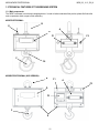
1
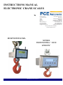
INSTRUCTIONS MANUAL ELECTRONIC CRANE SCALES by PCE Americas Inc. 711 Commerce Way Suite 8 Jupiter FL-33458 USA From outside US: +1 Tel: (561) 320-9162 Fax: (561) 320-9176 [email protected] PCE Instruments UK Ltd. Units 12/13 Southpoint Business Park Ensign way Hampshire / Southampton United Kingdom, SO31 4RF From outside UK: +44 Tel: (0) 2380 98703 0 Fax: (0) 2380 98703 9 [email protected] www.pce-instruments.com/english www.pce-instruments.com MCW PROFESSIONAL MCWR2 PROFESSIONAL ‘’ INOX VERSION‘’ MCW_03_14.11_EN_U MCW-MCWR2 PROFESSIONAL MCW_03_14.11_EN_U INDEX 1 GENERAL INFORMATION ............................................................................................................................................... 3 1.1 INTRODUCTION ........................................................................................................................................................................ 3 1.1.1 Designation of the machine and manufacturer data ........................................................................................................... 3 1.1.2 Premises ............................................................................................................................................................................ 3 1.1.3 Symbols.............................................................................................................................................................................. 4 1.1.4 General instructions ........................................................................................................................................................... 5 1.1.5 Destination of use............................................................................................................................................................... 5 1.1.6 Typical CE conformity declaration ...................................................................................................................................... 6 1.1.7 Markings ............................................................................................................................................................................. 7 1.1.8 Periodic metrological verification ...................................................................................................................................... 11 1.1.9 Directives and reference norms ....................................................................................................................................... 11 1.2 TECHNICAL FEATURES OF THE WEIGHING SYSTEM........................................................................................................ 12 1.2.1 Main components ............................................................................................................................................................. 12 1.2.2 Crane scale dimensions ................................................................................................................................................... 14 1.2.4 Features ........................................................................................................................................................................... 17 1.2.5 Environmental operating features .................................................................................................................................... 17 1.2.6 Remote control: keys and commands .............................................................................................................................. 18 1.2.7 Radio module features ..................................................................................................................................................... 18 1.3 GENERAL SAFETY NORMS ................................................................................................................................................... 19 1.3.1 Laws and national norms ................................................................................................................................................. 19 1.3.2 General warnings ............................................................................................................................................................. 19 1.3.3 Organisational measures of the user company ................................................................................................................ 21 1.3.4 Indications and warnings regarding the crane scale ........................................................................................................ 22 1.3.5 Indications and bans for working in safe conditions ......................................................................................................... 26 1.3.6 Environmental conditions ................................................................................................................................................. 29 2 USER MANUAL .............................................................................................................................................................. 30 2.1 USER ........................................................................................................................................................................................ 30 2.1.1 Professional features........................................................................................................................................................ 30 2.1.2 Location ............................................................................................................................................................................ 30 2.1.3 Clothing and equipment ................................................................................................................................................... 30 2.2 DESCRIPTION OF THE MACHINES AND CONTROLS ......................................................................................................... 31 2.2.1 Power supply – Start-up – Switch-off .............................................................................................................................. 31 2.2.2 Front panel keys and indicators ....................................................................................................................................... 32 2.2.3 Symbols on the LCD display ............................................................................................................................................ 33 2.3 BASIC FUNCTIONS ................................................................................................................................................................. 36 2.3. 1 Functioning with remote control ...................................................................................................................................... 36 2.4 FUNCTIONING ......................................................................................................................................................................... 37 2.4.1 Quick reference ................................................................................................................................................................ 37 2.4.2 Functioning modes ........................................................................................................................................................... 38 3 TECHNICAL INFORMATION .......................................................................................................................................... 39 3.1 PACKAGING, TRANSPORT, HANDLING, STORAGE, AND INSTALLATION ...................................................................... 39 3.1.1 Packaging......................................................................................................................................................................... 39 3.1.2 Transport, handling, storage ............................................................................................................................................ 39 3.1.3 Installation ........................................................................................................................................................................ 40 3.2 MAINTENANCE AND CHECKS............................................................................................................................................... 40 3.2.1 Daily monitoring................................................................................................................................................................ 40 3.2.2 Regular Maintenance ....................................................................................................................................................... 41 3.2.3 Maintenance registry ........................................................................................................................................................ 45 3.2.4 Clean ................................................................................................................................................................................ 47 3.2.5 Replacing the remote control batteries ............................................................................................................................ 47 3.2.6 Electronic crane scale battery: instructions and recharge ................................................................................................ 48 3.2.7 The battery recharge by optional kit ................................................................................................................................. 49 3.3 DECOMMISSIONING AND DISPOSAL ................................................................................................................................... 52 4 WARRANTY .................................................................................................................................................................... 53 2 MCW-MCWR2 PROFESSIONAL MCW_03_14.11_EN_U 1 GENERAL INFORMATION 1.1 INTRODUCTION Dear Customer, We thank you for choosing a Dini Argeo product and we invite you to carefully read this manual before carrying out any operation on the instrument that you have purchased. It is of utmost importance that the main checks and maintenance or repair interventions be recorded in the appropriate section of the booklet. Therefore we kindly ask you to carefully keep this booklet and present it to the manufacturer Dini Argeo or to the authorised reseller each time that it is necessary to carry out maintenance, repair, or replace spare parts / accessories on the instrument. NOTE: This manual is an integral part of the instrument and if sold, it must be given to the new owner. 1.1.1 Designation of the machine and manufacturer data The instrument "MCW" is a precision electronic weighing machine, it is to be considered as equipment, removable after carry out its weighing function (rif. UNI EN 13155/2009). Its installation on the lifting system should be limited to the needs of weighing requirements and must be removed after operation. The dynamometer is suitable to be used on overhead gantry cranes, fixed cranes, hiab`s or similar lifting equipment. It is composed by a tension load cell, an electronic device to measure and indicate the weight, a shackle connecting the hook of the lifting means and the load cell, and an eye hook for the connection between swivel hook and load lifting devices. The shackles for the connection are an integral part of the instrument and cannot be removed or replaced. The use of the instrument free of crickets is not allowed. Normally the remote command of the measuring instrument takes place through an infrared ray system. It is possible also to use radio devices both for the remote commands as well as for the data transmission (RF). With a regard to the load cell and its components sizes, the equipment can have maximum capacities ranging from 300 Kg to 6t. Finally, the instrument may be suitable for use with a third part (M) or for internal use. In the event that the instrument is suitable for internal use is characterized by the possibility to operate in multiple weighing ranges each with its own resolution (division: B1W1,B1W2,B1W3) see section “MARKING” This manual takes into consideration the various types. MANUFACTURER’S DATA: DINI ARGEO srl – via della Fisica , 20 - 41042 Spezzano di Fiorano (MO) - Italy Tel. 0536-843418 Fax 0536-843521 1.1.2 Premises The purpose of this manual is for the user to know all the fundamental norms and criteria for the installation, the correct use and for carrying out the correct maintenance of the purchased instrument. Therefore: This manual contains all the scale’s user instructions and the necessary knowledge for its correct and safe use. This manual supplies the useful instructions for the correct functioning and maintenance of the relative electronic crane scale; it is therefore important to pay careful attention and refer to all those sections which illustrate the simplest and safest way to operate. This publication, or any part of it, can be reproduced without the written authorisation by the Manufacturer. PS: The person responsible for the use of the weight indicator must make sure that all of the safety rules in force in the country of its use should be applied, to guarantee that the equipment is used in conformity with the use for which it is destined and avoid any dangerous situation for the users. Any attempt of tampering or modifying the instrument by the user or non authorised personnel, or improper use, or different than what is foreseen in this manual, will relieve the Manufacturer from all responsibility in the case of damages caused by people or things. 3 MCW-MCWR2 PROFESSIONAL MCW_03_14.11_EN_U 1.1.3 Symbols Please find below the symbols in the manual which recall the operator’s attention, in regards to the various danger levels. The danger levels will be subdivided in four classes of importance: DANGER!! CAREFUL!! CAUTION!! Concept or procedure which, if not carried out accurately, causes the danger or harsh personal injuries in case of accident. Concept or procedure which, if not carried out accurately, can cause harsh personal injuries or damages to the instrument in case of accident. In case of an accident, concept or procedure which can cause damages to the instrument or materials or adjacent to it, if it does not carry out accurately. WARNING: Important information or procedure which advises the operator regarding the optimal use of the system and on all the connected work modes. Besides the symbols of the four different danger levels, other symbols used, will be shown: - in the manual to recall the attention of the reader; - on the instrument to recall the attention of the user. Declaration of Conformity. Identifies the Class Of Precision defined by the OIML to represent 3000 divisions “TECH.MAN.REF.” means that an advanced function is being described (therefore for the technical personnel) which will be further explained in the corresponding technical manual. The crossed-out wheeled bin on the product means that at the product end of life, it must be taken to separate collection or to the reseller when a new equivalent type of equipment is purchased. The adequate differentiated refuse collection in having the product recycled helps to avoid possible negative effects on the environment and health and supports the recycling of the materials of which the equipment is made. The unlawful disposal of the product by the user will entail fines foreseen by the current regulations. It is forbidden to halt or transit under suspended load. 4 MCW-MCWR2 PROFESSIONAL MCW_03_14.11_EN_U 1.1.4 General instructions The warnings shown in this manual recall the ATTENTION OF THE OPERATOR in regards to information or procedures which advise the best use of the equipment in order to: - work safely; - lengthen the duration and functionality; - avoid the damages or loss of the programming; - optimise the work by taking into account the metric and safety norms in force in the country where it is used; The crane scale is to be considered a scale, and therefore should only be used as a weighing instrument. Therefore any improper use, or different than what is foreseen in this manual, will relieve the Manufacturer of all responsibilities in case of damages, direct or indirect, caused to people or things. For the indications and warnings for working in safety conditions see the “GENERAL SAFETY NORMS” section. 1.1.5 Destination of use The “MCW” instrument is a non automatic weighing device, to be considered as removable equipment load handling, suitable to be used on cranes, or on similar lifting devices. In regards to the weight measurement it is possible to identify the following operating conditions: - use for determining the weight for commercial transactions. - use for determining the weight for internal use. The name of the device models suitable to be used for commercial transactions are distinguished by a final letter M and APPROPRIATE MARKINGS (see section “MARKINGS”). The device can be used only in ordinary work environments. For further details see section “ENVIRONMENTAL CONDITIONS”. 5 MCW-MCWR2 PROFESSIONAL MCW_03_14.11_EN_U 1.1.6 Typical CE conformity declaration DICHIARAZIONE DI CONFORMITA’ DECLARATION OF CONFORMITY KONFORMITÄTSERKLÄRUNG DÉCLARATION DE CONFORMITÉ DECLARACIÓN DE CONFORMIDAD Fabbricante: Manufacturer: Hersteller: DINI ARGEO srl Fabricant: Fabricante: Dinamometro elettronico modello: Electronic crane scale model: Electronische Kranwaage Modell: MCW / MCWR2 Dinamomètre électronique modèle: Gancho pesador electrnico modelo: Anno di costruzione: Manufacturing year: Herstellungsjahr: Année de fabrication: Año de construcción: Numero di serie: Serial number: Seriennummer: Numéro de série: Número de serie: E’ conforme alle direttive: -Conforms to the directives: / Konform mit folgenden richtlinien ist: / Est conforme aux directives: / Es conforme a las directivas: 2004/108/CE - Compatibilità Elettromagnetica -Elecrtomagnetic Compatibility / Elektromagnetische Kompatibilität / -Con riferimento alle norme armonizzate: -With reference to these harmonised norms: / Mit Bezug auf die Normen: / En référence aux normes harmonisées: / Con referencia a las normas armonizadas: (CEI EN 61000-6-2 / 2006 ; CEI EN 61000-6-4 / 2007 ; CEI EN 61326-1 / 2007 ; CEI EN 55011 / 2009) 2006/42/CE - Macchine -Machines / Maschinen / Machines / Máquinas UNI EN 13155 / 2009 ; UNI EN 13889 Dichiara inoltre che: Declares also that: / Der Hersteller erklärt auβerdem, dass: / Déclare également que: / Declara también que: -La persona autorizzata a costituire il fascicolo tecnico presso la sede del fabbricante è la Direzione Tecnica. The person authorised to compose the technical file at the premises of the manufacturer is the Technical Management. / Die autorisierte Person, die die technischen Dokumente im Firmensitz des Herstellers verwaltet, ist das technische Management. / La personne autorisée à constituer le dossier technique chez la siége du fabricant est le directeur technique. / La persona autorizada a constituir el expediente técnico en la sede del fabricante es la Dirección Técnica. Data/Date/Datum Firma/Signature/Unterschrift 6 MCW-MCWR2 PROFESSIONAL MCW_03_14.11_EN_U 1.1.7 Markings On the equipment one will find a label on which there are shown the metrological and technical information as well as the relative CE marking of the instrument. CAUTION!! For no reason the data or closing and legalisation seals on the instrument’s plate, must be modified or removed. In case of tampering or removal of this information, the warranty of the instrument ceases, and the manufacturing company is released from any eventual damage, direct or indirect, caused to people or to things. THE LABELS ARE OF THE ADHESIVE TYPE, WHICH DETACH THEMSELVES WHEN DESTROYED. Marking for devices suitable for internal use: 5 11 8 4 9 10 7 1 6 3 2 In which: 1 Company name and fabrication status 2 Name of the machine 3 Name of the machine model and the type of installed electronic device 4 Serial Number (sn) 5 CE Markings 6 Power supply voltage 7 Symbol of the dumpster: indicates that at the end of its useful life the product must be disposed in the appropriate waste collection bins 8 Instrument’s precision class 9 Measuring field: Max= maximum capacity or full range of the instrument; Min= minimum weigh. Weighing accuracy is not guaranteed below this value; e= division value 10 Space reserved for the CE type approval certificate number 11 Building year of the machine 7 MCW-MCWR2 PROFESSIONAL MCW_03_14.11_EN_U Markings for devices suitable for internal use (multi-range): 5 11 8 4 3 10 7 1 6 9 2 In which: 1 Company name and fabrication status 2 Name of the machine 3 Name of the machine model and the type of installed electronic device 4 Serial Number (sn) 5 CE Markings 6 Power supply voltage 7 Symbol of the dumpster: indicates that at the end of its useful life the product must be disposed in the appropriate waste collection bins 8 Instrument’s precision class 9 Measuring field: Max= maximum capacity or full range of the instrument; Min= minimum weigh. Weighing accuracy is not guaranteed below this value; e= division value 10 Space reserved for the CE type approval certificate number 11 Building year of the machine 8 MCW-MCWR2 PROFESSIONAL MCW_03_14.11_EN_U Markings for devices suitable for commercial transactions: 13 11 6 5 4 12 10 9 1 8 3 7 2 In which: 1 Company name and fabrication status 2 Name of the machine 3 Name of the machine model and the type of installed electronic device 4 Serial Number (sn) 5 CE Markings 6 Space reserved for the number of the notified body 7 Conformity marking (instrument subject to metrological check) 8 Power supply voltage 9 Symbol of the dumpster: indicates that at the end of its useful life the product must be disposed in the appropriate waste collection bins 10 Space reserved for the CE type approval certificate number 11 Instrument’s precision class 12 Measuring field: Max= maximum capacity or full range of the instrument; Min= minimum weigh. Weighing accuracy is not guaranteed below this value; e= division value 13 Building year of the machine 9 MCW-MCWR2 PROFESSIONAL MCW_03_14.11_EN_U Markings on the load cell: 2 3 1 5 4 In which: 1 CE marking 2 Name of the series or model of the load cell 3 Serial number (sn) 4 Maximum useful load (maximum capacity) 5 With the issuing of the July 22nd, 2005 nr. 151 decree-law, relative to the European Directive 2002/96/EC in regards to the Waste Electrical and Electronic Equipment (known as WEEE), the relative manufacturers are called to intervene and manage the life cycle end of their introduced products. All the WEEE products must have impressed an easily visible and undeletable crossed-out dumpster. Therefore the manufacturers must offer all the instruments necessary for a correct disposal of this equipment. 10 MCW-MCWR2 PROFESSIONAL MCW_03_14.11_EN_U 1.1.8 Periodic metrological verification For all weighing instruments used in commercial transactions, it must be ascertained that the metrological features and the measurement reliability are kept in time. A periodic metrological verification is, therefore compulsory; the periodicity and the verifying person depend on the laws / regulations of the country in which one is operating. 1.1.9 Directives and reference norms List of the EC directives taken into reference: - 2009/23/EC (Non automatic weighing instruments) - 2004/108/EC (Electromagnetic compatibility) - 2006/95/EC (Low Voltage) - 2006/42/EC (Machines) - 1999/5/EC (Radio equipment); only version with radio module - 2002/95/EC ; 2003/118/EC ; 2002/96/EC ( RoHS and WEEE ) List of norms or other documents taken into reference: - FEM1.001 - UNI EN 13155/2009 - UNI EN 13889 - CEI EN 61000-6-2 / 2006 - CEI EN 61000-6-4 / 2007 - CEI EN 61326-1 / 2007 - CEI EN 55011 / 2009 - 1999/519/EC recommendation (only version with radio module) - ETSI EN 301489-3 1.4.1 version (only version with radio module) - ETSI EN 300220-2 2.1.1 version (only version with radio module) 11 MCW-MCWR2 PROFESSIONAL MCW_03_14.11_EN_U 1.2 TECHNICAL FEATURES OF THE WEIGHING SYSTEM 1.2.1 Main components The “MCW” instrument is an electronic weighing device. In order to better understand this product, please find below the main components which are part of this machinery. MCW PROFESSIONAL: B E A D F1 F2 C F4 MCWR2 PROFESSIONAL (INOX VERSION): B F1 A F2 D F3 C E 12 MCW-MCWR2 PROFESSIONAL A: B: C: D: E: F1: F2: F3: F4: MCW_03_14.11_EN_U body in which there is the tension load cell; shackle for connection between the lifting device hook and the load cell; eye hook to connect the swivel body to the lifting devices; electronic device for converting the signal coming from the transducer into a weight unit, with measurement display, and command and adjustment systems; hole predisposed for the outlet of the antenna (the version with radio module); hole prepared for RS232 serial connection to any external devices (hole is protected by a stainless steel cap screw threaded); Connector for connecting to external power supply through "jack"; Integrated thermal printer, upon request (only for the "MCWR2"). Centering washers for the lower hook (only for the MCW3000 and MCWT6 models). These are essential for the correct functioning of the crane scales; without these washers, the lower hook will not maintain the central position and the instrument will show an incorrect weight. In MCW electric crane scale, power is supplied by a rechargeable 6 V- 4,5 Ah to be inserted into the battery box located on the back of the equipment. 13 MCW-MCWR2 PROFESSIONAL MCW_03_14.11_EN_U 1.2.2 Crane scale dimensions MCW PROFESSIONAL: DIMENSIONS EXPRESSED IN mm MODEL MCW3000 MCW6T A 450 450 B 187 187 C 34 34 D 260 260 14 E 55 55 F 240 240 G 58 58 H 38 45 MCW-MCWR2 PROFESSIONAL MCW_03_14.11_EN_U MCWR2 PROFESSIONAL (INOX VERSION): G E B 120 A F 175 C D 290 DIMENSIONS EXPRESSED IN mm MODEL MCW150R2 MCW300R2 MCW600R2 MCW1500R2 A 340 340 340 340 B 180 180 180 180 C 24 24 24 24 D 290 290 290 290 15 E 70 70 70 70 F 224 224 224 224 G 43 43 43 43 H 30 30 30 30 MCW-MCWR2 PROFESSIONAL MCW_03_14.11_EN_U 1.2.3 Size of shackles and hooks The electronic crane scale "MCW" comes with 1 shackle and 1 eye hook. The accessories supplied have the following characteristics. SAFETY PIN SHACKLE MODEL MCW150R2 MCW300R2 MCW600R2 MCW1500R2 MCW3000 MCWT6 CAPACITY [t] 3,25 3,25 3,25 3,25 3,25 6,5 A [mm] 16,5 16,5 16,5 16,5 16,5 22 A [inch] 5/8 5/8 5/8 5/8 5/8 7/8 MATERIAL PIN EYE HOOK C [mm] 20 20 20 20 20 25 D [mm] 106 106 106 106 106 146 E [mm] 60 60 60 60 60 84,5 F c.s [mm] 22 6 22 6 22 6 22 6 22 6 29 6 WEIGHT [kg] 0,75 0,75 0,75 0,75 0,75 1,87 Bonified 6-degree highly resistant steel RAL 3001 red pin with metric threading MODEL MCW150R2 MCW300R2 MCW600R2 MCW1500R2 MCW3000 MCWT6 MATERIAL FINISH B [mm] 27,5 27,5 27,5 27,5 27,5 37 CAPACITY [t] 3,20 3,20 3,20 3,20 3,20 8 A [mm] 103 103 103 103 103 166 B [mm] 163 163 163 163 163 264 C [mm] 32 32 32 32 32 51 Hardened alloy steel. Raw or red painted. 16 D [mm] 33 33 33 33 33 47 E [mm] 62 62 62 62 62 101 WEIGHT [kg] 0,91 0,91 0,91 0,91 0,91 3,95 MCW-MCWR2 PROFESSIONAL MCW_03_14.11_EN_U 1.2.4 Features ACCURACY +/- 0.05% of full scale PROTECTION DEGREE IP 67 POWER SUPPLY 6 Vdc – 4,5 Ah rechargeable internal battery, standard, range of about 60 hours. 12 Vdc with external power supply 100 ÷ 240 Vac (50÷60 Hz)/12 Vdc standard. DISPLAY MCW - Backlit 25 mm LCD display with 6 digits. KEYBOARD Water resistant key polycarbonate membrane with tactile feedback. AUTO POWER OFF Adjustable from 1 to 255 minutes of no use, disinsertable. LOW BATTERY WARNING "Low bat" shown on the display. MEASUREMENT UNIT AVAILABLE g= grams, kg= kilograms, t= tons, Lb= pounds. IN CALIBRATION PHASE CONTAINER Sturdy stainless steel, against dust and splashes. I/O SECTION - 1 RS232/TTL input/output - 1 RS232/input/output for connection to PC/PLC OPTIONS WIFI Module, Bluetooth, RF radio THE PARTS OF THE INSTRUMENT CONTAINING DANGEROUS ELECTRICAL TENSION ARE ISOLATED AND INACCESSIBLE TO THE USER UNLESS IT HAS BEEN DAMAGED, OPENED, OR ALTERED. 1.2.5 Environmental operating features OPERATING TEMPERATURE RELATIVE HUMIDITY From -10 to +40°C. From 10 to 85 % without condensation 17 MCW-MCWR2 PROFESSIONAL MCW_03_14.11_EN_U 1.2.6 Remote control: keys and commands Along with the “MCW” electronic crane scale, an infrared remote control is supplied with which it is possible to repeat the keyboard functions. Alternatively it is possible to have a 6-key radio remote control. The type of remote control to be used must be selected in the Setup environment, in the << ir.ConF >> step. NOTE: The infrared remote controls are for indoor use only. CAUTION!! Do not press the keys with hard and/or pointed objects; only use fingers. The functioning instructions are described in section “FUNCTIONING WITH REMOTE CONTROL”. 1.2.7 Radio module features The version with the radio module allows communicating in radio frequency with eventual external devices (PC, printer or weight repeater); it is fitted with two multipoint radio frequency modules; one is installed on the measurement device and the other on the remote unit. The multi channel radio module functions in a frequency band, without need of license. WORK FREQUENCY From 868 to 870 MHz 18 MCW-MCWR2 PROFESSIONAL MCW_03_14.11_EN_U 1.3 GENERAL SAFETY NORMS The user must respect the manufacturer’s recommendations for the crane scale; one must respect the prescriptions requested by the manufacturer of the lifting device, and those highlighted in the eventual safety data sheet of the product which must be weighed. 1.3.1 Laws and national norms Before putting into service and while using it, the user must ascertain that all norms in force in the country, where the instrument is used in regards to “safety and prevention of casualties” and “metrology”, are respected. It is also important to take into account and respect the laws and guidelines of the Bodies assigned to the safety control of the country of use. 1.3.2 General warnings DO NOT exceed the nominal capacity of the crane, of the scale or of any support element of the load fixed onto the scale. Use the scale EXCLUSIVELY for the lifting and the weighing of suspended loads and for TENSION measurements. Do not stand or pass under a suspended load Suspended loads which may cause applied torsion stresses MUST be hung with flexible or swivelling bindings. Carefully respect all the safety measurements established by the manufacturer of the electronic crane scale, which are shown in the instruction manual. 19 MCW-MCWR2 PROFESSIONAL MCW_03_14.11_EN_U It is forbidden to exceed the nominal capacity of the crane, the scale, or any support element of the load that is fixed onto the scale. The electronic crane scale is to be considered a scale, and therefore use should be limited to only weighing needs. Therefore any improper use or use that is different than what is foreseen, will relieve the Manufacturer from all responsibilities in case of damages caused to people or things. Entrust the installation, set-up, maintenance, operations only to trained personnel. Entrust the execution of maintenance operations only to trained personnel in security controls for lifting devices. Remove the scale at the end of the weighing operation. DO NOT spill liquid on the instrument. The crane scale is to be considered like scale, and therefore it must be used only as a weighing instrument. The dynamometer is not designed for cargo handling. Therefore, an improper or different use than what is foreseen in this manual, will release the Manufacturer from all responsibilities in case of damages caused to people or things. 20 MCW-MCWR2 PROFESSIONAL MCW_03_14.11_EN_U 1.3.3 Organisational measures of the user company - Respect the safety measures established by the manufacturer of the electronic crane scale, the manufacturer of the lifting device, and eventually of the safety board of the product to be weighed. - The electronic crane scale must be used only for the foreseen purposes. - Entrust the use of the instrument only to expert and trained people, also with experience in using the lifting equipment. - Entrust the execution of installation, putting into function, maintenance, and repair operations only to specialised personnel (section “MAINTENANCE AND VERIFICATIONS”). - Make sure that the user manual is always available where the scale is used. - Carefully read and apply what described in the section “POWER SUPPLY – START-UP – SWITCH-OFF". - The nominal capacity of the scale must be equal or greater than the crane. If the nominal capacity of the scale is greater than the maximum capacity of the crane, make sure that loads, which are greater than the maximum capacity of the crane or of any support element of the load, are lifted. - Use only original spare parts. - Do not remove or replace shackles and hooks supplied - All the indicator connections must be made respecting the norms applied in the installation zone and environment. - Periodic verification with registry. - The electronic crane scale must be submitted to regular maintenance and repair interventions (see section “MAINTENANCE AND VERIFICATIONS”). - File the test result and conserve it in the test register. - When one notices anomalies while using the electronic crane scale, IMMEDIATELY stop all operations and do not reuse the instrument until the instrument has been submitted to specific controls by specialised and authorised personnel. Incorrect use, but reasonably foreseeable, by untrained people entails a non acceptable residual risk. 21 MCW-MCWR2 PROFESSIONAL MCW_03_14.11_EN_U 1.3.4 Indications and warnings regarding the crane scale It is strictly FORBIDDEN for non authorised personnel to enter in the operating zone. It is strictly FORBIDDEN to use the dynamometer with other shackles and hooks than those supplied. It is strictly FORBIDDEN to walk or halt below or near suspended loads. It is strictly FORBIDDEN to exceed the nominal capacity of the crane, the scale or of any load support element fixed to the scale. It is strictly FORBIDDEN to lift loads exceeding the maximum capacity of the MCWN, which is shown on the sides of the instrument. 22 MCW-MCWR2 PROFESSIONAL MCW_03_14.11_EN_U The crane scale is to be considered a scale, for all purposes, and therefore should only be used as a weighing instrument. Monitor the lifting of the load. During lifting, pay attention to the movement of the load. Lift the load the least distance to do the weighing. Use the scale EXCLUSIVELY for lifting and weighing the suspended loads and for TENSION measurements. Place the crane so that the load is lifted vertically. Place the load without causing knocks using a low speed of the crane. 23 MCW-MCWR2 PROFESSIONAL MCW_03_14.11_EN_U Once the load harnessing operation is done, move away, and make sure that the load is well balanced lifting it up a few centimetres from the ground. Use structures with single hitch elements which allow a correct alignment of the scale. Do not use structures with single hitch large-sized elements which could block the correct alignment near the hitch point. Suspended loads which can cause applied torsion stresses MUST be hung with flexible or swivelling bindings. It is FORBIDDEN to make oblique moves and rotations on the load 24 MCW-MCWR2 PROFESSIONAL MCW_03_14.11_EN_U Carefully read and apply what described in section “POWER SUPPLY – START-UP – SWITCH-OFF”. Periodically check the integrity of all the scale parts (see section “MAINTENANCE AND VERIFICATIONS”). Any maintenance, repair, or cleaning operations must be made with the electronic crane scale turned off (see section “MAINTENANCE AND VERIFICATIONS”). Use the DPI prescribed by the manufacturer of the lifting system and eventually those highlighted in the safety data sheet of the weighing article (helmet, accident-prevention shoes, etc.). DANGER!! The nominal capacity of the electronic crane scale must not be lower than the maximum capacity of the lifting device. 25 MCW-MCWR2 PROFESSIONAL MCW_03_14.11_EN_U 1.3.5 Indications and bans for working in safe conditions It is FORBIDDEN to use the equipment for lifting or transporting people. It is FORBIDDEN pull or drag loads, apply only vertical stress Do NOT exceed the rated capacity of the crane, scale or any bearing element attached to the scale. NO! DO NOT swing the load by pushing it or putting it beyond the work area of the lifting device. 26 MCW-MCWR2 PROFESSIONAL MCW_03_14.11_EN_U NO! DO NOT use multiple attachment points. NO! DO NOT push, nor pull the load or the loaded scale. NO! DO NOT pull the hook from the side. It is FORBIDDEN to use the device for weighing radioactive materials or melded masses DO NOT stretch obliquely the load. 27 MCW-MCWR2 PROFESSIONAL MCW_03_14.11_EN_U It is FORBIDDEN to make any changes to the scale DO NOT PASS BELOW THE LOAD It is FORBIDDEN to use other shackles or hooks than those supplied DO NOT spill liquid on the instrument. DO NOT use solvents or industrial chemicals for cleaning the instrument 28 MCW-MCWR2 PROFESSIONAL MCW_03_14.11_EN_U 1.3.6 Environmental conditions DO NOT install in an area with risk of explosion DO NOT expose the instrument to direct sunlight or near sources of heat DO NOT expose the instrument to strong magnetic or electrical fields. DO NOT install the instrument in an environment at risk of corrosion It is FORBIDDEN to use the device beyond the temperature range from -10 ° C to +40 ° C It is FORBIDDEN to use the device outdoors or in very humid environments 29 MCW-MCWR2 PROFESSIONAL MCW_03_14.11_EN_U Protect the electronic crane scale from the high humidity, vapours, liquids or powders. If the electronic crane scale is installed in a much warmer environment than it was before, it can form an undesired condensation (condensation of humid air on the device). In this case, turn off the electronic crane scale and wait until it adapts to the temperature of the environment (approximately 2 hours) 2 USER MANUAL 2.1 USER 2.1.1 Professional features The staff assigned to the electronic crane scale and all activities related to it must: - Have appropriate physical and mental characteristics; - Be an expert or have sufficient knowledge on lifting equipment and be trained in the proper use of scales; - Be familiar with the requirements of labour protection and accident prevention in the field; - Be able to evaluate the safety condition of the lifting equipment; - Understand the safety signs on the machine, the warnings and the messages highlighted in the manual of the instrument, even if he does not have a good command of the language in which the crane operates; - Be able to make oneself understood in the workplace. 2.1.2 Location The operator of lifting equipment, which was installed on the crane scale, must not only respect the safety conditions but is also responsible for accidents that may occur around the machine. Therefore, the operator must place himself in a working position which is safe for people, things, and vehicles in the workplace. In particular, the operator must: - Be very careful to never position below the load or in positions which could be dangerous if there was a rupture of an accessory of lifting equipment; - Always have a good visibility of the load and eventual personnel nearby; - Evacuate the people and things from the work area; 2.1.3 Clothing and equipment The personnel must wear clothing and be fitted with personal protective equipment required for the lifting vehicle used (helmets, protective gloves, safety shoes, etc..). 30 MCW-MCWR2 PROFESSIONAL MCW_03_14.11_EN_U 2.2 DESCRIPTION OF THE MACHINES AND CONTROLS 2.2.1 Power supply – Start-up – Switch-off The instrument is powered by a 6 VDC internal rechargeable battery. It is possible to charge the battery through the 12V power adapter (supplied) which should be connected to the 230 Vac mains voltage. TO TURN ON the instrument press the C key until the indicator turns on; then release. The display shows in sequence: XX.YY is the installed software version. bt XXX in which XXX is a number from 0 to 100 which indicates the battery level. The indicator has an “auto zero at start-up” function: in other words it means that if at start-up a weight within +/- 10% of the capacity is detected, it will be zeroed; if the weight is not within this tolerance, with a non approved instrument the display shows the present weight after a few instants, while with an approved instrument “ZEro” is shown continuously on the display, until the weight does not re-enter within this tolerance; the auto zero function at start-up may be disabled in the set-up environment (only with non approved instrument); see SEtuP >> ConFiG >> PArAM. >> Auto-0 parameter (TECH.MAN.REF.). By pressing the ZERO key for an instant while the version is shown in the display, the indicator will show the following in this order: CLoCk if there is the optional board with date and time. XX.YY in which XX indicates the instrument type, YY indicates the metrological software version. XX.YY.ZZ is the installed software version. XXXXXX is the name of the installed software. bt XXX in which XXX is a number from 0 to 100 which indicates the battery level. -K- X.YY in which K identifies the type of keyboard: K=0 5-key keyboard, K=1 17-key keyboard. X.YY is the installed software version. After this, “hi rES” is displayed (in case of non approved instrument) or “LEGAL” and the g gravity value (in case of approved instrument), then the programmed capacity and minimum division, and finally it executes a countdown (selfcheck). TO TURN OFF the instrument keep the C key pressed until the “- oFF –“ message appears on the display; then release the key. 31 MCW-MCWR2 PROFESSIONAL MCW_03_14.11_EN_U 2.2.2 Front panel keys and indicators The front panel is projected in order to make easy and immediate use of the indicator by the user; it consists of a display to 6 digits 25mm high, a film waterproof keyboard with 5 keys. During the weighing, different symbols indicating the status of multifunction operation are also activated (see section “SYMBOLS ON THE LCD DISPLAY”). 2 1 1 Indicates the presence of power supply. 2 Sensor for the reception of the infrared signal. 32 MCW-MCWR2 PROFESSIONAL SCALE KEY MCW_03_14.11_EN_U FUNCTION - Zeros the displayed gross weight, if it is within +/- 2% of the total capacity. - Cancels the negative tare value. - When entering numbers it decreases the digit to be modified. - If pressed for a long time, it allows to enter the USER MENU (see paragraph “USER MENU”). - If pressed for an instant it carries out the semiautomatic tare. - If pressed at length it allows entering the manual tare from keyboard. - Cancels the negative tare value. - In the numeric input phase it increases the digit to be modified. - It carries out a specific function of the operating mode set in the set-up environment. - In the numeric input phase it selects the digit to be modified, from left to right. - It carries out a specific function of the operating mode set in the set-up environment. - In the numeric input phase, it confirms the entry made. - In the SET-UP, it allows to enter a step or to confirm a parameter within a step. - It transmits the data from the serial port dedicated to the printer. - It turns the instrument on and off. - In the numeric input phase, it quickly zeros the present value. - In the SET-UP, it allows to exit a step without confirming the change made - Allows viewing the scale’s metric information: capacity, division, minimum weigh for each configured range. 2.2.3 Symbols on the LCD display The LCD display has symbols which show the indicator’s functioning status; you will find the description for each symbol below. 33 MCW-MCWR2 PROFESSIONAL NUMBER SYMBOL (1) 0 (2) ~ (3) (4) NET (5) G (6) B (7) (8) MCW_03_14.11_EN_U FUNCTION The weight detected on the weighing system is near zero, within the interval of –1/4 ÷ +1/4 of the division. The weight is unstable. The time is being shown on the display, in the “HH:MM:SS” format. The displayed weight is a net weight. The displayed value is a gross weight, if the Italian or English language is selected in the print configuration. The displayed value is a gross weight, if the German, French or Spanish language is selected in the print configuration. Indicates the battery charge level: see section “LOW BATTERY WARNING”. MAX= When viewing the metric information, it identifies the indicated capacity range. MIN= When viewing the metric information, it identifies the indicated minimum weigh range. e= When viewing the metric information, it identifies the indicated division range. (9) LT The locked tare is enabled. (10) PT The manual tare is active. W1 The instrument is in the first weighing range. W2 The instrument is in the second weighing range. W3 The instrument is in the third weighing range. (11) (12) Indicates the number of the active scale. 34 MCW-MCWR2 PROFESSIONAL MCW_03_14.11_EN_U (13) PCS The number of pieces is being displayed. (14) Kg Indicates the unit of measure in use (“kg” for kilogram, “g” gram). (15) % Indicates the percentage of the weight on the scale (“Sample Weight Percentile” functioning mode). (16) T Indicates the unit of measure in use (tons). (17) LB Indicates the unit of measure in use (pounds). These are displayed around the digits with higher sensitivity, when viewing the weight x 10. (18) (19) * (20) (21) PEAK HOLD SP1 SP2 (22) SP3 SP4 Indicates that a key has been pressed. The PEAK function is enabled. The HOLD function is enabled. Indicates that the Weight < Target - t.Min : see section “+/- TOLERANCE CHECK (ChECK)”. Indicates that the Target - t.Min ≤ Weight ≤ Target + t.MAX: see section “+/TOLERANCE CHECK (ChECK)”. Indicates that the Weight > Target + t.MAX: see section “+/- TOLERANCE CHECK (ChECK)”. Indicates that the Weight ≥ thresh: see section “+/- TOLERANCE CHECK (ChECK)”. 35 MCW-MCWR2 PROFESSIONAL MCW_03_14.11_EN_U 2.3 BASIC FUNCTIONS 2.3. 1 Functioning with remote control “19-key” infrared remote control The command system is “directive”, therefore the receiving measurement device must be “in view”; the maximum functioning distance is 8 m. With this type of remote control, the functioning of the keys will be as described in the following table. FUNCTION OF THE KEYS REMOTE CONTROL KEY KEY OR FUNCTION EMULATED It allows to select the desired function; see section “ADDITIONAL FUNCTIONS WITH THE 18-KEY AND 19KEY REMOTE CONTROLS”. If pressed at length it changes the display intensity. C key or stand-by function if pressed at length. Entry of digits. Tare key or increase of a digit while entering a value. . or display of scale info. Zero key or decrease of a digit while entering a value. Mode key or it scrolls the digits to the right while entering a value. Print or enter key. Not managed. Not managed. F1 C NUMERIC KEYS TARE / . ZERO / MODE / PRINT / F2 F3 To enable this mode one has to select “ir 19” in the << ir.ConF >> step. 36 MCW-MCWR2 PROFESSIONAL MCW_03_14.11_EN_U 2.4 FUNCTIONING 1) Suspend the instrument from the crane it will be used on and press push-button “C” for a few seconds: all segments on the display will light for a few seconds as the MCW conducts a lamp and other self-tests. 2) After the self-tests, if the display shows a non-zero value without a load on the scale, press the "ZERO” key. 3) If any accessories have been applied to the crane scale (connection rings, chains, hooks etc.) it is necessary to press the "TARE" key (or by using the remote control’s TARE button). NOTES: - The "TARE" key can be used with any weight applied in the range of its capacity. - If slings are used to handle the load, make sure that the load is properly balanced and that the slings are positioned properly. 4) When the display indicates “0", the instrument is ready for use. 5) Start lifting the load slowly. 6) If the load is greater than the full-scale value (not maximum capacity), the display will show " ¯ ¯ ¯ ¯ ¯ ", which means overload. Unload to avoid any need for recalibration. 7) To switch off the instrument, keep the C key pressed until the “– oFF –“ message appears on the display. DANGER!! If, during the weighing operations with the crane scale, one views the " ¯ ¯ ¯ ¯ ¯ " (Over Load) message, one should IMMEDIATELY stop the weighing operations and quickly place on the ground the load attached on the crane scale. 2.4.1 Quick reference TARE Press Press Press 2 sec Press Press ENABLE SELECTED MODE MANUAL TARE (PT) Press CANCEL Press 2 sec ON / OFF CONFIRM PRINT Press 3 sec 37 INFO: Max, Min, e MCW-MCWR2 PROFESSIONAL MCW_03_14.11_EN_U 2.4.2 Functioning modes STANDARD Press SWITCH Kg / Lb NET / GROSS Press SWITCH NET / GROSS SETPOINT Press 2 sec IN / OUT Press IN WEIGH ALIBI MEMORY Press TYPE REWRITING ID TYPE VALUE Press OUT WEIGH TYPE ID TOLERANCE CHECK Press TARGET TOL.- PERCENTAGE Press MIN WEIGHT TOL. + Press SWITCH % - WEIGHT Press 2 sec SAMPLE TYPE % VALUE DISPLAY x10 Press ENABLE / DISABLE x10 HOLD or PEAK Press ENABLE / DISABLE HOLD or PEAK Press SINGLE WEIGHING Press TOTAL TOTALISER PIECE COUNTING Press Press 2 sec GRAND TOTAL Press SWITCH PCS - WEIGHT Press 2 sec SAMPLE TYPE PCS NR. 38 MCW-MCWR2 PROFESSIONAL MCW_03_14.11_EN_U 3 TECHNICAL INFORMATION 3.1 PACKAGING, TRANSPORT, HANDLING, STORAGE, AND INSTALLATION 3.1.1 Packaging The instrument is delivered in a box for transport. Package contents: - 1 lifting shackle. - 1 lifting eye hook. - External power (12Vdc) - Infrared remote control. - Instruction manual and REGISTER FOR MAINTENANCE AND WARRANTY. - Certificate of calibration. - CE Declaration of Conformity. Before making the first user verification, make sure that the package contains all the items in the above list and that the material has not been damaged during the transport. 3.1.2 Transport, handling, storage During transportation of the electronic crane scale, it is obligatory to use their package that protects the instrument from impact or falls. For transportation, one must consider that the package should not be compressed in neither the top nor side by any external bodies. It is important that the board and the electronic crane scale itself are stored indoors to meet the environmental conditions mentioned above (see paragraph “ENVIRONMENTAL CONDITIONS”). The weight of the box varies depending on the model: MODEL MCW150R2 MCW300R2 MCW600R2 MCW1500R2 MCW3000 MCWT6 SIZES mm (l x w x h) 480X300X400 480X300X400 480X300X400 480X300X400 480X300X400 480X300X400 WEIGHT(including packing) 19(21) kg 19(21) kg 19(21) kg 19(21) kg 14(16) kg 14(16) kg Sizes: Length (l) x width (w) x height (h) CAREFUL!! Take care when handling the package to avoid collisions or falls that could be harmful to humans and / or instrument. If necessary, carry out the handling procedure with the help of various people or with the appropriate aids. 39 MCW-MCWR2 PROFESSIONAL MCW_03_14.11_EN_U 3.1.3 Installation Inside the package, all provided parts of the system are placed. The equipment is not provided ready to use, consequently it must perform certain operations in order to start the instrument. The installation steps are: - Open the box containing the electronic crane scale. - Install the "shackle" on the upper side of the load cell. - Install the "eye hook" on the rotating body. - Make sure that the nut shackle is quite screwed and that the pin is well placed. - Make sure that the shackle is completely screwed. - Carefully check the suitability of the crane hook in which the crane scale will be installed. - Connect the system to the safety hook of the crane, taking care that the "shackle" rests on the saddle of the crane hook and its lever is safely positioned. - The system slinging completed, go properly away and lift a few inches the crane scale. - The crane scale is supplied with battery already installed. Thus, pressing the C button on the front panel, the electronic crane scale can be switched on and used immediately. CAREFUL!! In case you need to replace the hook and/or shackle contact the Authorized Service Center. 3.2 MAINTENANCE AND CHECKS The electronic crane scale and all lifting accessories must be regularly subjected to inspection and maintenance. For the prevention of accidents or damages, it is necessary that the maintenance is done according to the manufacturer's instructions. Maintenance must be performed only by persons who have acquired the necessary technical expertise. To ensure a safe operation, follow these instructions: - carry out a continuous regular maintenance and cleaning. - entrust the maintenance and repair operations only to trained and authorized personnel. - use only original spare parts. - do not use the electronic crane scale where there is non-compliance with the safety checklist. - any maintenance, repair or cleaning should be done out from danger areas and with the electronic crane scale turned off. 3.2.1 Daily monitoring Each time the operator starts a new work cycle with the electronic crane scale, one must: - check all instrument parts; - carry out a general visual inspection of the whole system; - check the integrity and efficiency of all parts of the weighing system like the safety lever of the hooks, the locking nuts screwed well with the pin, the shackles, etc.. 40 MCW-MCWR2 PROFESSIONAL MCW_03_14.11_EN_U 3.2.2 Regular Maintenance Maintenance should be carried out only by persons who have acquired the necessary technical expertise and are specialized and trained for this purpose. Every 3 months - Check all dimensions of the parts which make up the instrument; - Check the wear on the handle or the eyelet, by checking if there are any plastic deformations, mechanical damages(irregular), cracks, corrosion, damage to threaded portions and the twists; - Check the tightness of the splice plate on the hook, and the presence of defects, and ensure its proper functioning; - Make sure that the split pin and the shackle nuts are firm; - If other metrological and mechanical irregularities are detected, have the electronic crane scale repaired by qualified personnel (authorized assistance service). An incorrect measurement of weight may be a sign of a mechanical problem with the dynamometer. If the dynamometer weighs bad, the dynamometer must be repaired by skilled personnel (Authorized Service Center). Do not for any reason carry out the repair by yourself. In case of non-compliance turn immediately off the electronic crane scale. Every 12 months All repair operations and the parts used are classified and stored in the maintenance register. All of the elements that transmit the load should be checked by specialised personnel qualified in inspection and maintenance of cranes and bridge cranes. It is of utmost importance that all the maintenance and repair operations, and the used pieces are recorded and filed in the appropriate produce maintenance registry. 41 MCW-MCWR2 PROFESSIONAL MCW_03_14.11_EN_U For further information on regular checks, see the following table: COMPONENT PART Locking bolts Pin Cricket Cricket surface Cotter pin Shape of the cricket Section Surfaces of hook and eye Hook and eye eyelet Hook Opening the hook Hook Slip on safety Apparatus Locking screws Frequency of tests Control Verify the presence of all components of the system General visual inspection of the entire system Control safety lever hook Check cotter pin cricket Cleaning and lubrification CONTROL LIMIT Loosening No slack allowed Deformation Dmax – 5% Wear Deformation Positioning No sign or deformation allowed Mandatory Elongation Bmax +5% Diameter Mechanical damage Smax -5% No mechanical damage allowed Dmax +5% Emax -10% Hmax -10% Wear and tear Corrosion Eyelet orientation It can not be twist Deformation Cmax +10% Twist Torsion > 10° Damage No damage allowed Loosening Daily Weekly Quarterly ● ● ● ● ● ● Marking the presence of the instrument Control of all the dimensions of the parts that make up the system Checking the wear of hooks, shackles and bells ● User ■ Specialized personnel 42 ■ ■ MCW-MCWR2 PROFESSIONAL MCW_03_14.11_EN_U Form and structure of the shackle: The shackles should be examined regularly by a qualified person. The time interval from one check to another depends on how much the instrument is used, but it is recommended to not exceed six months. Therefore, one must: - always inspect the shackle before use; - carry out regular visual inspections to look for nicks, cracks, wear or damaged areas, damaged threads on the pivot and body; if it is necessary, carry out a magnetic test or non-destructive testing; - keep a file in regards to the accessory sheet and keep track of the checks; - the shackles which do not fully or partially satisfy the requirements, must be discarded. Form and structure of the hook: The eye hook should be examined periodically by a competent person. The interval among the inspections depends on the frequency of use of the instrument, but it is recommended not to exceed six months. 43 MCW-MCWR2 PROFESSIONAL MCW_03_14.11_EN_U Therefore, during: - a visual inspection (monthly): He must perform a cold cleaning and check for worn parts, burrs, cracks. As to fork hooks, make sure that the pivot is not worn or deformed and it slides into its place. The hook cannot be deformed. The spring must be positioned the hook correctly on the tip of the hook. As to locking hooks, make sure the locking system works properly and ensure the safety closure, which in these conditions must lean on the hook without leaving open spaces and should not oscillate side to side. - Dimensional (quarterly) pay particular attention to: Entrance: it must not exceed 10% of the nominal size. Worn parts: next to where the slings are rested and to the maximum stress section the worn parts must not be inferior to the 95% of the original size of their original sizes (see next figure). The markings must be legible. Misalignments: to the plane of symmetry. The hub: the diameter should not be less than 10% of the nominal value. The eye: the reduction of the section in a perpendicular direction should not be greater than 10% compared to the nominal diameter. Is the zone of maximum tension, the area where the hook is stressed at the physical level. Is the zone of maximum wear, because it is the point where the load is lifted and the materials they touch. The hooks, which do not pass the checks laid down, must be-eliminated and substituted 44 MCW-MCWR2 PROFESSIONAL MCW_03_14.11_EN_U 3.2.3 Maintenance registry In order to cope with problems like the wear of the mechanic and electronic components, and the grip load devices, it is necessary that one carries out a regular and systematic maintenance. The maintenance and respective time intervals must take place according to the indications of the manufacturer shown in the instructions manual of the instrument. The maintenance interventions must be made only by specialised and qualified personnel. The maintenance person must have attended training courses and must know the safety norms in the use of crane scales and concretely apply them. In this booklet the user must document in chronological order all the maintenance interventions carried out on the crane scale (inspection/control, revision, repair), as well as any fact or particular event which might have influenced safety matters. Upon receipt of the dynamometer, or at least before the commissioning of the instrument, make sure all sizes of hooks and shackles and bring in the service manual. All subsequent dimensional checks specified in the plan check and maintenance, will be compared with the first measurement and the tolerance limits given in the above table, refer to the actual size detected in the first inspection. In the following pages of this booklet there is a “maintenance registry” in which all ordinary and extraordinary maintenance interventions on your instrument, should be reported. All information is very important and can invalidate the validity of the warranty in the case that it’s not reported in detail and accurately. It is also advisable to make sure that: - the internal responsible person carries out the quarterly verification and regularly records it on this booklet; - the authorised personnel stamps the appropriate box at the end of each annual maintenance intervention. 45 MCW-MCWR2 PROFESSIONAL MCW_03_14.11_EN_U MCW-MCWR2 PROFESSIONAL MCW_03_14.11_EN_U 3.2.4 Clean If the electronic crane scale is often used in different places, especially in places with the presence of dust and moisture, it is necessary to have the instrument regularly cleaned. Clean the keyboard of electronic crane scale with a soft damp cloth with a detergent or a mild detergent solution. CAUTION!! Do not use any type of solvent or industrial chemical product while cleaning the instrument and all the system parts. 3.2.5 Replacing the remote control batteries As mentioned above, the MCW electronic crane scale is supplied with a remote control that duplicates the functions of the keyboard. When using the remote control, the battery may die and must be replaced. To replace the batteries in the remote control, carry out the following steps: - take out the battery box placed on the back of the remote control; - replace the old battery with a new one and make sure that it’s correctly inserted; - reinsert the box with the new battery in the remote control. 47 MCW-MCWR2 PROFESSIONAL MCW_03_14.11_EN_U 3.2.6 Electronic crane scale battery: instructions and recharge As mentioned earlier, the power supply in MCW electronic crane scale is provided through a rechargeable 6V – 4,5 Ah, to be included in the box on the back of the equipment (see section “MAIN COMPONENTS”). In order to prevent problems with the battery, it is recommended to remove the battery from the load cell, if the electronic crane scale is not used for a long time so as not to cause damage to both the battery and the crane scale itself. CAREFUL!! Never throw the battery into the fire, will bring them closer to sources of heat can cause explosions and injuries. The electronic crane scale displays "LoW.BAt" when the batteries are about to complete their life cycle. In this case, it is necessary to connect the crane scale to external power (12Vdc) to fully recharge the battery. In order to recharge the battery, you must: - Remove the rubber cap from the connector on the back of the crane scale; - Insert the jack of the feeder (12V) in the connector on the back of the instrument; - Insert the power supply (12V) in the power outlet at 230VAC; Later, on the indicator front panel lights the LED power-on LED lights. 48 MCW-MCWR2 PROFESSIONAL MCW_03_14.11_EN_U 3.2.7 The battery recharge by optional kit If there would need to use the MCW crane scale constantly, it is possible to request an optional kit including a spare battery pack and charger adapter. To perform a battery change and development its functions, perform the following steps: 1) Unscrew the screws "manual" on the back of the machine.. Screw out 2) Slowly remove the battery pack. 3) The battery is connected internally to the electronic card of the instrument thanks to an AMP automotive connector. 49 MCW-MCWR2 PROFESSIONAL MCW_03_14.11_EN_U 4) Unplug the connector automotive AMP from the battery pack. 5) Connect the charger to the battery pack by the auto-motive AMP connector. 50 MCW-MCWR2 PROFESSIONAL MCW_03_14.11_EN_U 6) Insert the power supply (12Vdc) to the network at 230Vac and plug the charger by the connection jack. Once the battery is charging, it is possible to connect the spare battery pack to the crane scale. CAREFUL!! The battery recharge must be performed using only the power supplied (12Vdc) supplied with the instrument. 51 MCW-MCWR2 PROFESSIONAL MCW_03_14.11_EN_U PHASE OF THE BATTERY RECHARGE BY CHARGER ADAPTER The charger’s led indicate the charge level reached: 1 2 3 4 LED 1 2 3 4 DESCRIPTION When lit, it indicates the presence of voltage. When lit, it indicates the presence of the battery; it means that the battery is connected correctly to the charger. When lit, it indicates that the battery is half charged . When lit, it indicates that the battery is fully charged. Once the full charge reached: - Disconnect the power supply charger. - Disconnect the battery charger. 3.3 DECOMMISSIONING AND DISPOSAL Each consumer should help protect the environment by reducing pollution risks and adopting a responsible attitude, according to the recycling norms in force in the country where the instrument is used. The symbol of the crossed garbage on the product indicates that, at the end of its useful life, the product must be given to appropriate centres for collection or returned to the distributor when purchasing a new equivalent product. A proper collection for recycling the product will prevent any negative effects on the environment and health and encourage the recycling of materials. Therefore, before disposing the product, it is necessary to separate the components of the instrument in each recycling category and place them in the appropriate collection centres. The unlawful disposal of the product by the user causes the application of the administrative sanctions foreseen by the law. 52 MCW-MCWR2 PROFESSIONAL MCW_03_14.11_EN_U 4 WARRANTY The two years warranty period begins on the day the instrument is delivered. It includes spare parts and labour repair at no charge if the instrument is returned prepaid to the dealer’s place of business. Warranty covers all defects not attributable to the Customer (such as improper use) and not caused during transport. If on site service is requested (or necessary), for any reason, where the instrument is used, the Customer will pay for all of the service technician’s costs: travel time and expenses plus room and board (if any). the Customer pays for the transport costs (both ways), if the instrument is shipped to dealer or manufacturer for repair. The warranty is voided in the event that the instrument is returned or if there are damages caused by: inobservance of indications in the manual, interventions by non authorised personnel, and/or non original spare parts, user incapacity and/or improper use, incorrect maintenance, loss or impossibility of presenting the maintenance booklet. This warranty does not provide for any compensation for losses or damages incurred by the Customer due to complete or partial failure of instruments, even during the warranty period. 53