1
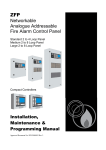
ZFP
Networkable
Analogue Addressable
Fire Alarm Control Panel
Standard 2 to 4 Loop Panel
Medium 2 to 8 Loop Panel
Large 2 to 8 Loop Panel
Compact Controllers
User Manual
& Log Book
Approved Document No. DFU5000501 Rev 3
ZFP Networkable Analogue Addressable Fire Alarm Panel
Table of Contents
1
IMPORTANT NOTES ............................................................................................................................... 3
2
INTRODUCTION ....................................................................................................................................... 4
3
USER RESPONSIBILITIES...................................................................................................................... 5
4
TOUCHSCREEN, INDICATORS & CONTROLS ................................................................................. 6
4.1
4.2
4.3
4.4
4.5
5
FRONT PANEL LAYOUT ............................................................................................................................. 6
TOUCHSCREEN .......................................................................................................................................... 6
TOUCHSCREEN BUTTONS .......................................................................................................................... 6
LED INDICATORS ...................................................................................................................................... 7
KEYSWITCH CONTROL .............................................................................................................................. 7
GENERAL USER OPERATION .............................................................................................................. 8
5.1
NORMAL CONDITIONS ............................................................................................................................... 8
5.1.1
5.2
5.3
5.4
5.5
6
ACCESS LEVEL 1 (AL1) CONTROLS AND MENU OPTIONS ....................................................... 13
6.1
6.2
6.3
6.4
6.5
6.6
7
Typical displays ......................................................................................................................................... 8
DISPLAYING AND RESETTING FIRE CONDITIONS ....................................................................................... 9
DISPLAYING AND CLEARING FAULT CONDITIONS ................................................................................... 10
DISPLAYING AND CANCELLING SYSTEM DISABLEMENTS ....................................................................... 10
DISPLAYING AND CANCELLING SYSTEM TESTS ...................................................................................... 11
HOW TO ENTER ACCESS LEVEL 1 (AL1) ................................................................................................. 13
ACCESS LEVEL 2 ..................................................................................................................................... 13
ACCESS LEVEL 3 ..................................................................................................................................... 13
LAMPS TEST ............................................................................................................................................ 13
VIEW ALARM COUNTER .......................................................................................................................... 14
CLEAN THE DISPLAY ............................................................................................................................... 14
ACCESS LEVEL 2 (AL2) CONTROLS AND MENU OPTIONS ....................................................... 15
7.1
7.2
7.3
7.4
7.5
7.6
7.7
7.8
HOW TO ENTER ACCESS LEVEL 2 (AL2) ................................................................................................. 15
SILENCING ACTIVE ALARM SOUNDERS................................................................................................... 16
RESOUNDING THE ALARM SOUNDERS ..................................................................................................... 16
RESETTING THE PANEL ........................................................................................................................... 16
ACCESS LEVEL 3 ..................................................................................................................................... 17
RESOUND SOUNDERS .............................................................................................................................. 17
EVENT LOG FUNCTIONS .......................................................................................................................... 17
DISABLEMENT FUNCTIONS ...................................................................................................................... 18
7.8.1
Supervisory Disablements ....................................................................................................................... 18
7.8.2
Enable/Disable Zones ............................................................................................................................. 19
7.8.3
Enable/Disable Devices ......................................................................................................................... 19
7.8.4
Enable/Disable Sounders ....................................................................................................................... 19
7.8.5
Enable/Disable Input Groups ................................................................................................................. 20
7.8.6
Enable/Disable Output Groups ............................................................................................................. 20
7.8.7
Enable/Disable Printer ............................................................................................................................ 20
7.8.8
Clear All Disablements ........................................................................................................................... 20
7.9 DISPLAYING AND CLEARING THE PANEL’S ALARM COUNTER ................................................................ 20
7.10
PRINTER PAPER FEED ......................................................................................................................... 21
7.11
SET PANEL’S TIME AND DATE ............................................................................................................ 21
User Manual & Log Book Approved Document No. DFU5000501 Rev 3 Page 2 of 24
ZFP Networkable Analogue Addressable Fire Alarm Panel
7.12
7.13
8
CHANGING ACCESS LEVEL 2 (AL2) ENTRY CODE ............................................................................. 21
SHOW SUPERVISORY EVENTS ............................................................................................................. 21
FIRE ALARM LOG BOOK .................................................................................................................... 22
Table of Figures
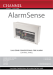
Figure 1 – Access Level 1 and Access Level 2 Menu Structure ........................................................................... 12
1 IMPORTANT NOTES
READ THIS SECTION BEFORE OPERATING THIS PRODUCT.
The fire alarm control panel is safe to operate provided it has been installed in accordance with the
manufacturer’s instructions and used in accordance with this user manual.
Hazardous voltages are present inside the panel. DO NOT operate the fire alarm control panel with the
enclosure open. There is no need to open the enclosure except to carry out commissioning, maintenance and
remedial work. This work must only be carried out by competent service personnel who are fully conversant
with the contents of the separate Installation and Programming Manual for this product and have the
necessary skills for maintaining the equipment.
If the panel is damaged in any way, expert advice should be sought regarding its repair.
Regular servicing of the fire alarm system is highly recommended, preferably on a continuous maintenance
contract and by a competent organisation. A full-itemised installation report should be obtained at least annually.
CE Marked
This product has been manufactured in conformance with the requirements of all applicable EU
Council Directives.
Disclaimer
Errors and omissions excepted. No responsibility can be accepted by the manufacturer or distributors of this
range of fire panels for any misinterpretation of an instruction or guidance note or for the compliance of the
system as a whole. The manufacturer’s policy is one of continuous improvement and we reserve the right to
make changes to product specifications at our discretion and without prior notice.
User Manual & Log Book Approved Document No. DFU5000501 Rev 3 Page 3 of 24
ZFP Networkable Analogue Addressable Fire Alarm Panel
2 INTRODUCTION
Note: A Quick Start User Guide (Document No. DFU5000502) is available for the ZFP Fire Alarm Control
Panel which should be read in conjunction with this user manual. The quick start guide summarises key
information provided in the user manual such as operator actions to be taken in the event of a fire alarm and
entering access levels.
Fire alarm systems - an overview
The primary purpose of a fire alarm system is to provide an early warning of a fire so that people and animals
can be evacuated and action taken to stop the fire as soon as possible - all according to a predetermined plan.
Alarms may be raised by automatic detection devices, or manually by a person operating a manual call point
(MCP).
To ensure an alarm is dealt with in an orderly manner, it is important to know where the alarm is coming from.
To aid this function, fire alarm systems are usually split into zones, each covering a different geographical area
of a building.
When an alarm has been raised, the panel responds by indicating the zone(s) in which the alarm has occurred and
activating all relevant outputs (sounders, bells, strobes, beacons, relays, etc.) to provide a warning of the fire.
The ZFP fire alarm control panel
The ZFP is a multi-loop, touchscreen-controlled, addressable fire alarm panel designed to work with a wide
range of intelligent fire detection devices. As such, it is able to provide much more detailed information about a
fire condition than just the number of the activated zone.
As well as giving prioritised feedback on the status of the system, its intuitive touchscreen will indicate the
name and location of every detector that has responded to a fire and also show the order in which they went into
alarm.
It will also display detailed information on any pre-alarm and/or fault conditions that arise and can be
programmed to operate in a number of different ways to help reduce the incidence of false alarms and to
encourage the orderly evacuation of a building in a true fire condition.
Controls are available that will allow authorised users to silence or reset a fire condition, to resound the alarm
sounders, to disable or enable parts of the system to suit prevailing conditions, to change the panel’s date and
time and to test the panel’s indicators to ensure they are working correctly.
All of these functions - and more - are explained in detail in this user manual.
An overview of the panel’s access levels
Three access levels are available at the panel - access level 1 (AL1), access level 2 (AL2) and access level 3 (AL3).
AL1 is the panel’s general user level which is accessible to everyone. The actions that can be performed at this
level are detailed in section 6.
AL2 is the panel’s authorised user level which is available to authorised, trained personnel only. Entry to this
level is achieved by either, the input of a special four-digit code using the panel’s touchscreen buttons, or by
turning the panel’s keyswitch anticlockwise to the horizontal position. The actions that can be performed at this
level are detailed in section 7.
AL3 is the panel’s engineering/programming level. ON NO ACCOUNT SHOULD ACCESS LEVEL 3 BE
ENTERED BY ANYONE EXCEPT AN AUTHORISED SYSTEMS ENGINEER. A FIRE PANEL IS A PIECE
OF LIFE SAFETY EQUIPMENT AND UNAUTHORISED ACCESS MAY AFFECT THE WAY THE PANEL
FUNCTIONS, ENDANGER LIFE AND VOID ITS WARRANTY. If you are an authorised engineer, details of
access level 3 can be found in the separate Installation & Programming Manual (Document No. DFU5000503).
User Manual & Log Book Approved Document No. DFU5000501 Rev 3 Page 4 of 24
ZFP Networkable Analogue Addressable Fire Alarm Panel
3 USER RESPONSIBILITIES
BS5839-1 is the British Standard code of practice for the design, installation, commissioning and maintenance
of fire detection and fire alarm systems for buildings. Section 7 of the standard (User Responsibilities) states
that a named responsible person should be appointed to supervise all matters pertaining to the fire alarm system
{clause 47.2a}.
Highlighted below is a summary of the main functions the responsible person is expected to carry out with
regard to BS5839-1 only. It does not highlight any other responsibilities that may be required of the user or
responsible person that are listed in documentation such as the Employers Guide to Fire Safety, the Fire
Precautions (Workplace) regulations and/or any other legislation relevant to the premises. If in doubt, the fire
authority can advise on the fire legislation that applies to any given building. For countries outside the UK,
different user responsibilities may apply.
BS5839-1 states the responsible person should:
(The bracketed numbers {xx} identify the BS5839-1 clauses to which the summary refers.)
1 Ensure the fire alarm panel is checked daily to confirm there are no faults on the system {47.2b}.
2 Ensure arrangements are in place for the test, maintenance and regular servicing of the system with regard to
Section 6 of the standard {47.2c}. Important: Clause 44 of BS5839-1 recommends weekly and monthly tests
that should be carried out by the responsible person. See below for details.
3 Ensure the Fire Alarm Log Book is kept up to date by recording fire signals, fault signals, work on the system,
etc., and make sure it is available for inspection at all times {47.2d / 48}.
4 Ensure all relevant occupants of the premises are instructed in the proper use of the system {47.2e}.
5 Take steps to limit the number of false alarms on the system {47f}.
6 Ensure the effectiveness of the system is not impaired by ensuring there is a space of at least 500mm in all
directions around and below every fire detector and that all manual call points are unobstructed and easy to see
{47g}.
7 Liaise with all relevant building engineers, decorators, etc., to ensure any changes to (or maintenance of), the
building’s fabric does not compromise the protection given by the fire alarm system, create faults or false alarms
{47h}.
8 Ensure that any structural or occupancy changes planned for the building are done so with due and early
consideration given to any changes that may be required to the fire system {47h}.
9 Ensure that a selection of spare parts are held as appropriate within the premises {47j}.
Routine weekly testing to be undertaken by the user/responsible person
To meet the requirements of Clause 44 of BS5839-1 we recommend the following tests are carried out at
approximately the same time each week, during normal working hours:
Note: It is essential any alarm receiving centre is contacted before, and after, these tests to avoid unwanted
alarms and to confirm the fire signal is correctly received.
• Carry out an Indicator lamp test to check all zone lights show and the beeper sounds.
• Operate a manual call point or automatic detector to test the fire alarm.
• Check that the alarm sounders operate.
• Reset the system by first pressing the
button and then pressing the
button.
• Verify that no manual call points or automatic detectors are obstructed in any way.
• Test a different zone each week using a different call point or detector so all zones are tested in rotation.
Routine monthly testing to be undertaken by the user/responsible person
Ensure authorised service personnel verify the system’s standby power supply, or batteries, are in good working
order.
Quarterly and periodic inspection, testing, servicing and maintenance
It is the user’s responsibility to ensure that an ongoing periodic plan is in place that meets Clause 45 (Inspection
and Servicing) of BS5839-1. The work required to meet this Clause must be carried out by a competent person
with specialist knowledge of fire detection and alarm systems. The standard recognises this will normally be an
outside specialist fire alarm servicing organisation.
Please note: the above summaries do not replace Sections 6 and 7 of BS5839-1 but are intended to help the user gain a greater understanding of his or her
responsibilities. We strongly recommend the named responsible person familiarises themselves with the full standard, copies of which are available from your
local reference library or can be purchased from the British Standards Institute, Customer Services Dept., 389 Chiswick High Road, London, W4 4AL. Tel: +44
(0)20 8996 9001. Web: www.bsi-global.com.
User Manual & Log Book Approved Document No. DFU5000501 Rev 3 Page 5 of 24
ZFP Networkable Analogue Addressable Fire Alarm Panel
4 TOUCHSCREEN, INDICATORS & CONTROLS
Depending on the model purchased, the ZFP range of fire alarm control panels include the following features:
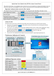
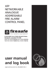
4.1
Front Panel Layout
Event buttons (change colour when active)
Example module (Z45)
with controls & indicators
Additional indicators:
Power, Fault, Access, etc.
Touchscreen
Keyswitch for
entry to access level 2
Event indicators:
Fire, Fault, Disablement, Test
Action buttons
Navigation buttons
ZFP Standard Panel
- displays user menus
- returns to previous menu
- scroll up
4.2
- scroll down
Touchscreen
The 4.3 inch colour LCD touchscreen provides access to the panel’s user menus and shows system status
information including active fire alarms, faults, disablements, tests and warning messages. It is the fire
panel’s man-machine interface.
4.3
Touchscreen Buttons
On initial power up, the following touch-sensitive buttons are available on the touchscreen:
Button
Description
Shows active fire alarms signals raised on the system from detectors, manual call
points, etc.
Changes colour from green to red when there are fire alarms on the system.
Shows active fault conditions on the system, including device faults, loop faults,
module faults, etc. The total number(n) of faults is also shown on this button.
Changes colour from green to yellow when there are faults on the system.
Shows active disablements on the system, including zones, sounders, devices, Input
Groups and Output Groups. The total number(n) of disablements is also shown on
this button.
Changes colour from green to yellow when there are disablements on the system.
Shows active tests on the system, e.g. panel is in walk test. The total number(n) of
tests is also shown on this button.
Changes colour from green to yellow when there are tests on the system.
Provides access to the panel’s user menus.
User Manual & Log Book Approved Document No. DFU5000501 Rev 3 Page 6 of 24
ZFP Networkable Analogue Addressable Fire Alarm Panel
Button
Description
Resets the panel when alarms have been cleared and the alarm sounders are silenced
(available at AL2 & AL3 only).
Silences the panel’s internal buzzer in a fire or fault condition.
Silences active alarm sounders (available at AL2 & AL3 only).
Returns the user to the touchscreen’s previous menu.
Depending on the status of the panel, these two buttons:
scroll vertically through the touchscreen’s menus,
scroll vertically through any fire, fault, disablement, or test conditions that
appear on the touchscreen,
manipulates date, time, disablement settings, etc.
4.4
LED Indicators
Various indicators are available on various panel modules. A partial listing is provided below:
Indicator
Fire (General)
Status
Flashing Red
Steady Red
Flashing Red
Fire Zones
(1 to 200)
Steady Red
Flashing Yellow
Fault
What this means
The panel has detected a fire alarm condition.
There is a ‘silenced’ fire alarm condition on the
system.
A fire alarm condition has been detected on the
specific zones which are flashing.
There is a ‘silenced’ fire alarm condition on
the specific zones which are lit steady.
There is a fault condition on the system.
Disablement
Steady Yellow
A manual disablement has been placed on the
system.
Test
Steady Yellow
The panel is in test mode.
Power
Steady Green
Supply Fault
Steady Yellow
Access
Steady Yellow
System Fault
Steady Yellow
Sounder Fault
Network Fault
Delays
Steady Yellow
The panel is supplied with power (either Mains or
backup batteries).
The panel’s has detected a fault with its power
supply, batteries, or Mains supply.
The panel is in access level 2 or 3.
A system error has occurred, such as a
microprocessor fault. Remains lit even if the
panel automatically clears the fault.
A fault has been detected on the panel’s sounder
circuits.
The panel’s sounders have been disabled.
Steady Yellow
A system network error has occurred.
Flashing Yellow
Flashing Yellow
Steady Yellow
4.5
What to do
See section 5.2
for details
See section 5.3
for details
See section 5.4
for details
See section 5.5
for details
Call the service
engineer
Call the service
engineer
Call the service
engineer
Call the service
engineer
One or more output delays have been programmed
into the panel by an authorised systems engineer.
A delay is running.
-
Keyswitch Control
Turning the keyswitch (if enabled) anticlockwise to the horizontal (I) position gives the
user instant entry to access level 2.
User Manual & Log Book Approved Document No. DFU5000501 Rev 3 Page 7 of 24
ZFP Networkable Analogue Addressable Fire Alarm Panel
5 GENERAL USER OPERATION
(MESSAGES THAT MAY APPEAR ON THE PANEL’S TOUCHSCREEN AND WHAT THEY MEAN)
The touchscreen provides feedback on the system’s current status. Priority is always given to the most
important current event, i.e. fire conditions will always override pre-alarms and/or fault conditions. This
section outlines the various messages that may be displayed and what they mean.
5.1
Normal Conditions
‘Operating mode’
shown here
Under normal operating conditions (shown left), with
no fires, faults or pre-alarms present, a message may
be displayed on the touchscreen indicating the current
operating mode of the panel. The operating mode is
programmed by an authorised systems engineer and is
defined by the client/system specifier. Refer to your
system specifier’s documentation for further details.
The following are typical operating mode messages,
but other mode messages may be displayed:
Normal is displayed when there are no fires, faults or pre-alarms on the system and the panel’s day/night
(building occupied/unoccupied) facility HAS NOT been set up by an authorised systems engineer.
Normal: occupied is displayed when there are no fires, faults or pre-alarms on the system and the panel is in
day (building occupied) mode.
Normal: unoccupied is displayed when there are no fires, faults or pre-alarms on the system and the panel is
in night (building unoccupied) mode.
5.1.1
Typical displays
User Manual & Log Book Approved Document No. DFU5000501 Rev 3 Page 8 of 24
ZFP Networkable Analogue Addressable Fire Alarm Panel
5.2
Displaying and Resetting Fire Conditions
In the event of a fire condition on a single zone:
the panel’s Fire (General) indicator will flash red.
the panel’s internal buzzer (if enabled) will sound.
the relevant Fire Zone indicator(s) on the panel will flash red.
the system’s alarm sounders, relays and other output devices will operate as programmed.
the green
the touchscreen shows the zone in which the fire originated (see example below).
button changes to red
button on the top line of the touchscreen.
Zone alarm button
(displays zone in fire condition)
Press the red zone alarm button (Zone 1- Reception Area
is shown in example left) to display a list of all active
fires within that zone (see example below):
If more than one device is in a fire condition on the zone,
the top right corner of the display will show, for example
“1 / 3” and can be scrolled through using the
and
buttons, or by using the scroll bar.
Note: Authorised users can silence and reset the system
by following the steps below. Details on how to enter
access level 2 can be found in section 7.1.
In the event of a fire condition, the designated responsible person on site should carry out the
building’s fire management plan. Depending on this plan you may:
Investigate the cause of the fire alarm and carry out the appropriate action to clear the alarm.
Press the
button to silence the alarm sounders, then enter the access level 2 code (if
requested), OR turn the panel keyswitch anticlockwise to the horizontal position. Note the sounders
can be started again by pressing the
button at access level 2.
Press the
After the fire alarm has been investigated, cleared and the alarm sounders silenced, press the
button to reset the panel, then enter the access level 2 (if requested), OR turn the
panel keyswitch anticlockwise to the horizontal position.
Note down the cause of the fire(s) in the Fire Alarm Log Book (see section 8).
button to silence the panel’s internal buzzer, if appropriate.
In the event of a fire condition on multiple zones:
the panel’s Fire (General) indicator will flash red, its internal buzzer (if enabled) will sound and the
relevant Fire Zone indicator(s) will flash red.
the system’s sounders, relays and other output devices will operate as programmed.
the green
the touchscreen will show the first zone in alarm, most recent zone in alarm and the total number of
zones in alarm.
button changes to red
button on the top line of the touchscreen.
To view any zones that are in fire and recommended actions to be taken, follow the procedure previously
listed above for a fire condition on a single zone.
User Manual & Log Book Approved Document No. DFU5000501 Rev 3 Page 9 of 24
ZFP Networkable Analogue Addressable Fire Alarm Panel
5.3
Displaying and Clearing Fault Conditions
In the event of a fault condition on the system:
one or more of the panel’s Fault indicators will flash yellow.
the panel’s internal buzzer (if enabled) will sound.
the green
button changes to yellow
Press the yellow
button on the top line of the touchscreen.
button and a window similar to the one shown below appears detailing the fault type
and location. Note: The total number(n) of faults is shown on this button (‘4’ shown in example below).
If there are more than one fault condition, the top right
corner of the display will show, for example “1 / 4” and
can be scrolled through using the
and
buttons, or
by using the scroll bar.
Zone fault button
(displays type and location of fault)
Press the yellow zone fault button (Zone 1 – Reception is shown in example above) to view additional details
about the displayed fault. For device specific faults, the loop number and address will be shown. For other
faults, information pertinent to that fault will be displayed instead.
In the event of a fault condition, the designated responsible person on site may:
Press the
button to silence the panel’s internal buzzer, if appropriate. Note that any
new faults will resound the buzzer.
Take appropriate steps to ensure the fault(s) is/are rectified.
Note down the nature of the fault(s) in the Fire Alarm Log Book (see section 8)
Note: Once faults have been cleared, the panel should auto-reset and return to a normal condition. If required,
the
button can be pressed but be aware that manually resetting the panel whilst faults are still
present, will not clear the faults, they will simply re-appear.
5.4
Displaying and Cancelling System Disablements
Note: Refer to section 7.8 for an explanation about enabling or disabling parts of the system.
In the event of a disablement being set on the system:
the panel’s Disablement indicator will be lit steady yellow.
the green
Press the yellow
button changes to yellow
button on the top line of the touchscreen.
button and a window similar to the one shown below appears detailing the type
and location of the disablement. Note: The total number(n) of disablements is also shown on this button (‘3’
shown in example below).
If there are more than one disablement, the top right corner of the display will show, for example “1 / 3” and
can be scrolled through using the
and
buttons, or by using the scroll bar.
Zone disablement button
(displays type and location of disablement)
User Manual & Log Book Approved Document No. DFU5000501 Rev 3 Page 10 of 24
ZFP Networkable Analogue Addressable Fire Alarm Panel
To cancel a specific disablement, press the individual blue zone disablement button (Zone 1 – Reception is
shown in example above). A small
button appears (shown below). Press this button to confirm
the cancellation.
5.5
Displaying and Cancelling System Tests
In the event of a test being carried out on the system:
the panel’s Test indicator will be lit steady yellow,
the green
Press the yellow
button changes to yellow
button on the top line of the touchscreen,
button and a window similar to the one shown below appears detailing the
location of the test. Note: The total number(n) of tests is also shown on this button (‘31’ shown in example
below).
If there are more than one test, the top right corner of the display will show, for example “1 / 31” and can be
scrolled through using the
and
buttons, or by using the scroll bar.
Zone test button
(displays type and location of test)
To cancel a specific test, press the individual blue zone test button (Zone 1 – Reception is shown in example
above). A small
button appears (shown below). Press this button to confirm the cancellation.
User Manual & Log Book Approved Document No. DFU5000501 Rev 3 Page 11 of 24
ZFP Networkable Analogue Addressable Fire Alarm Panel
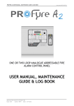
Figure 1 – Access Level 1 and Access Level 2 Menu Structure
User Manual & Log Book Approved Document No. DFU5000501 Rev 3 Page 12 of 24
ZFP Networkable Analogue Addressable Fire Alarm Panel
Figure 1 shows the menu and sub menus available at both access levels 1 & 2.
6 ACCESS LEVEL 1 (AL1) CONTROLS AND MENU OPTIONS
Access level 1 is available to general users and allows basic operator actions to be performed including:
View any fire conditions (see section 5.2) or fault conditions (see section 5.3).
View any system disablements (see section 5.4) or zones that are being tested (see section 5.5).
Test the panel’s LED indicators to ensure they are working correctly.
Determine the total number of times the panel has been in a fire condition.
Gain entry to access level 2 (authorised user level) and access level 3 (authorised systems engineer).
Clean the touchscreen.
6.1
How to Enter Access Level 1 (AL1)
Entry to Access Level 1 does not require a code inputting.
With the panel operating under normal conditions (shown below left), press the
panel’s touchscreen to show the access level 1 menu options (shown below right).
Menu options can be navigated using the touchscreen’s
and
button on the
buttons.
The panel automatically exits access level 1 after 30 seconds without a button press.
Menu options available at access level 1 are explained in sections 6.2 to 6.6.
6.2
Access Level 2
See section 7.1 for details.
6.3
Access Level 3
Access level 3 is the panel’s engineering/programming level. ON NO ACCOUNT SHOULD ACCESS LEVEL 3
BE ENTERED BY ANYONE EXCEPT AN AUTHORISED SYSTEMS ENGINEER. Details of access level 3
can be found in the separate Installation & Programming Manual (Document No. DFU5000503).
6.4
Lamps Test
This function tests the panel’s LED indicators to ensure they are working correctly.
At Access Level 1, press the
button. All of the panel’s LED indicators will illuminate
steady for approximately two seconds and the panel’s internal buzzer (if enabled) will also sound. If any of
the indicators fail to illuminate, report the fault(s) to the designated site engineer and make a note of it in the
Fire Alarm Log Book (see section 8).
User Manual & Log Book Approved Document No. DFU5000501 Rev 3 Page 13 of 24
ZFP Networkable Analogue Addressable Fire Alarm Panel
6.5
View Alarm Counter
This function shows the total number of times the panel has been in a fire alarm condition.
At Access Level 1, press the
button and a display similar to the one shown below appears.
The display will show the total number of times the panel has been in an alarm condition since it was last
cleared (upper button) AND the total number of alarms from its installation date (lower button).
Pressing either of these buttons has no effect.
6.6
Clean the Display
This function disables all the touchscreen buttons for approx. 100 seconds, allowing the touchscreen’s
display to be wiped clean using a barely damp cloth. Detergents or solvents should not be used to clean the
panel and ensure water does not enter the enclosure.
User Manual & Log Book Approved Document No. DFU5000501 Rev 3 Page 14 of 24
ZFP Networkable Analogue Addressable Fire Alarm Panel
7 ACCESS LEVEL 2 (AL2) CONTROLS AND MENU OPTIONS
Access level 2 is available to authorised, trained personnel only and allows additional operator actions to be
performed including:
View any fire conditions (see section 5.2) or fault conditions (see section 5.3).
View any system disablements (see section 5.4) or zones that are being tested (see section 5.5).
Enable or disable zones, sounders, Input Groups, Output Groups and system devices.
Display, filter, print or reset the panel’s event and alarm history.
Set the panel’s time and date.
Gain entry to access level 3 (authorised systems engineer).
Change the entry code to access level 2 from its factory default.
Silence the alarm sounders (see section 7.2).
Resound the alarm sounders (see section 7.3).
Reset the panel (see section 7.4).
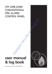
7.1
How to Enter Access Level 2 (AL2)
Access level 2 is accessible by either, inputting of a four-digit code using the panel’s touchscreen, OR alternatively,
turning the panel’s keyswitch anticlockwise to the horizontal position.
Entry to AL2 using the panel’s touchscreen
With the panel operating under normal conditions (shown below left), press the
panel’s touchscreen to show the access level 1 menu options (shown below right).
Press the
button on the
button and the display shown below appears:
Enter the access level 2 code by pressing the buttons on
the touchscreen’s numeric keypad.
Note: Default code entry to access level 2 is: 3
3 3 3.
If the code does not work, it may have been changed by
an authorised user/engineer. A record of the access level
2 code may be recorded below:
.....
.....
.....
.....
Also, the default access level 2 code can be changed to suit (see section 7.12).
User Manual & Log Book Approved Document No. DFU5000501 Rev 3 Page 15 of 24
ZFP Networkable Analogue Addressable Fire Alarm Panel
As soon as the code has been entered correctly, the access level 2 menu options are displayed (shown below
left). Scroll down
to view additional access level 2 menu options (shown below right).
Menu options can be navigated using the touchscreen’s
and
buttons.
The panel automatically exits access level 2 after 5 minutes without a button press.
Entry to AL2 using the panel’s keyswitch
With the panel operating under normal conditions, turn the panel’s keyswitch anticlockwise to the horizontal
position to gain instant entry to access level 2.
Menu options available at access level 2 are explained in sections 7.5 to 7.13.
7.2
Silencing Active Alarm Sounders
At Access Level 2, press the
button to silence any active alarm sounders.
The alarm sounders will stop sounding and the panel’s general Fire and relevant Fire Zone indicators will go
steady red.
Should a fire condition occur on another zone whilst the alarm sounders are silenced, the panel:
Will sound the sounders programmed for activation by the new zone(s) in alarm.
Will flash its general Fire and appropriate Fire Zone indicator(s) for any new zone(s) in alarm.
May, if programmed, automatically reactivate the silenced alarm sounders and flash any related Fire
Zone indicator(s).
7.3
Resounding the Alarm Sounders
This function is only available if relevant to the panel’s status, i.e. when the alarm sounders have been
silenced by an authorised user by pressing the
button (see section 7.2).
At Access Level 2, press the
7.4
button and the alarm sounders will resound.
Resetting the Panel
After the cause of an alarm has been cleared and the alarm sounders have been silenced.
At Access Level 2, press the
button to reset the panel.
The panel touchscreen will indicate the reset process has started and, after a few seconds, the Fire Zone
indicators and general Fire indicator will go out indicating the process is complete. If there are still any fire
conditions on any zones, the panel will go back into alarm.
User Manual & Log Book Approved Document No. DFU5000501 Rev 3 Page 16 of 24
ZFP Networkable Analogue Addressable Fire Alarm Panel
7.5
Access Level 3
Access level 3 is the panel’s engineering/programming level. ON NO ACCOUNT SHOULD ACCESS LEVEL 3
BE ENTERED BY ANYONE EXCEPT AN AUTHORISED SYSTEMS ENGINEER. Details of access level 3
can be found in the separate Installation & Programming Manual (Document No. DFU5000503).
7.6
Resound Sounders
See section 7.3 for details.
7.7
Event Log Functions
This function lists and filters the panel’s event, alarm or fault log. Also, a hard copy of each log may be
printed using the onboard printer (if fitted).
At Access Level 2, press the
button and the window shown below appears:
The Show Event Log button, when pressed, lists both the
panel’s event and alarm log (up to 20,000 events). This
includes fire, fault and system events.
The Show Alarm Log button, when pressed, lists only the
panel’s alarm log. Typically, alarm events include activated
fire alarms, panel silenced and panel reset.
The Show Fault Log button, when pressed, lists the
panel’s fault log. Typically, faults include missing devices,
earth faults, open/short circuit faults and watchdog resets.
The window shown left is a typical list of saved events.
Press the
and
buttons (or use the scroll bar) to scroll
through the list. Events are listed in chronological order with
the most recent listed first. When the log is full, the oldest
record is deleted and replaced by the newest record.
Event log button
(displays both panel events and alarms)
To either filter, or print, the log press one of the blue event
log buttons and the window shown left is displayed:
The Filters button, when pressed, allows events to be listed
by Date Range or Device Address.
The Print Event Log button, when pressed, allows you to
print a hard copy of the panel’s log to the onboard printer
(if fitted).
User Manual & Log Book Approved Document No. DFU5000501 Rev 3 Page 17 of 24
ZFP Networkable Analogue Addressable Fire Alarm Panel
7.8
Disablement Functions
This function allows you to enable, or disable, parts of the system including zones, individual devices,
sounders, Input Groups, Output Groups and the panel’s printer (if fitted).
Remember, any active disablement(s) can be viewed (and cleared) at any access level by pressing the yellow
button on the top line of the touchscreen (see section 5.4).
Note: It is strongly recommended that all disablements are regularly reviewed and immediately cleared when
no longer necessary as they can have a major effect on how the system works.
At Access Level 2, press the
button and a window similar to the one shown below appears.
Note: If a function is unavailable it will be ‘greyed’ out, e.g. the Panel Printer button.
7.8.1
Supervisory Disablements
This function is only available when there are hidden ‘supervisory’ disablements on the system, which are
programmed by an authorised systems engineer.
At Access Level 2 > Disablement Functions, press the
button and a window similar
to the one shown below appears detailing the type and location of the disablement.
Note: The total number(n) of disablements is also shown on the yellow
button (‘3’ shown in
example below).
If there are more than one disablement, the top right
corner of the display will show, for example “1 / 3” and
can be scrolled through using the
and
buttons,
or by using the scroll bar.
To cancel a specific disablement, press the individual blue disablement button (Disabled Sounder A located
in Zone 1 – Reception Area is shown in the example). A small
button appears (shown below).
Press this button to confirm the cancellation.
User Manual & Log Book Approved Document No. DFU5000501 Rev 3 Page 18 of 24
ZFP Networkable Analogue Addressable Fire Alarm Panel
7.8.2
Enable/Disable Zones
This function allows you to disable (and re-enable) all zones or selected zones, from reporting fires, faults, prealarms, etc., and is normally used to temporarily disable detectors, including manual call points, in a selected
zone. For example, in areas where work is being carried out that could trigger an erroneous fire alarm.
At Access Level 2 > Disablement Functions, press the
to the one shown below left appears:
button and a window similar
Press the
and
buttons (or use the scroll bar) to scroll the display through all available zones. Toggle
a selected zone’s enabled/disabled state by pressing the individual zone button (Zone 1 status is shown
changed from enabled to disabled in the example above). After changing a zone’s state, press the
button and the window shown below appears.
Confirm the zone’s status change by pressing the
button.
Important Note: The status change ONLY becomes
effective AFTER the
button has been pressed.
7.8.3
Enable/Disable Devices
This function allows system devices to be disabled (and re-enabled) from reporting fires, faults, pre-alarms,
etc., and is normally used to temporarily disable detectors/manual call points that are nuisance tripping.
At Access Level 2 > Disablement Functions, press the
below appears:
button and the window shown
Press the By Zone button to select and disable all devices
within a specific zone, or press the By Address button to
select and disable individual devices by entering their loop
number and address.
Follow the same operating procedure previously listed in
section 7.8.2.
7.8.4
Enable/Disable Sounders
This function is used to disable (and re-enable) one or more sounders from sounding in a fire condition.
Note: Sounders include the panel’s conventional sounders (powered from the panel) and loop sounders (loop
powered) and form part of an Output Group, which are programmed by an authorised systems engineer.
At Access Level 2 > Disablement Functions, press the
operating procedure previously listed in section 7.8.2.
button and follow the same
User Manual & Log Book Approved Document No. DFU5000501 Rev 3 Page 19 of 24
ZFP Networkable Analogue Addressable Fire Alarm Panel
7.8.5
Enable/Disable Input Groups
This function is used to disable (and re-enable) one or more Input Groups from activating. Note: Input
Groups comprises of detectors, MCPs, inputs of I/O units, keyswitches and other input devices and are
programmed by an authorised systems engineer.
At Access Level 2 > Disablement Functions, press the
operating procedure previously listed in section 7.8.2.
7.8.6
button and follow the same
Enable/Disable Output Groups
This function is used to disable (and re-enable) one or more Output Groups from activating. Note: Output
Groups comprises of loop and conventional panel sounders, beacons, outputs of I/O units, relays and other
output devices and are programmed by an authorised systems engineer. This function is typically used to
disable, for example, auto-diallers and other ancillary equipment from activating during routine maintenance.
At Access Level 2 > Disablement Functions, press the
operating procedure previously listed in section 7.8.2.
7.8.7
button and follow the same
Enable/Disable Printer
This function is used to disable (and re-enable) the panel printer (if fitted).
At Access Level 2 > Disablement Functions, press the
operating procedure previously listed in section 7.8.2.
7.8.8
button and follow the same
Clear All Disablements
This function is used to globally clear all current disablements on the system.
At Access Level 2 > Disablement Functions, press the
operating procedure previously listed in section 7.8.2.
7.9
button and follow the same
Displaying and Clearing the Panel’s Alarm Counter
This function shows the total number of times the panel has been in a fire alarm condition.
At Access Level 2, press the
button. The display will show the total number of times the
panel has been in an alarm condition since it was last cleared (upper button) AND the total number of alarms
from its installation date (lower button). A typical example is shown below left:
Press the
button to return to the main access level 2 menu, or to clear the alarm counter press the
‘upper’ blue button. A small Clear Counter? button will appear (shown above right). (Note that the Total
Alarms counter cannot be reset.)
Press the Clear Counter? button and the ‘Alarms since’ counter will reset and start counting any new fire
conditions from the current date.
User Manual & Log Book Approved Document No. DFU5000501 Rev 3 Page 20 of 24
ZFP Networkable Analogue Addressable Fire Alarm Panel
7.10 Printer Paper Feed
This function is only available if relevant to the panel’s status, i.e. if the panel has a printer module fitted.
At Access Level 2, press the
button to feed paper from the onboard printer.
7.11 Set Panel’s Time and Date
This function is used to set the panel’s time and date, which is required for accurate logging of events in the
panel’s log. The panel has a real-time 24 hour clock with default time and date settings. An automatic DST
(Daylight Saving Time) option is available which will automatically adjust the panel’s clock one hour forward
on the last Sunday in March and one hour backward on the last Sunday in October.
At Access Level 2, press the
button and a window similar to the one shown below appears:
Adjust the time and date using the touchscreen’s
numeric keypad and
buttons. Also, set/unset
the daylight saving time by pressing the DST tick box.
When correct, press the
main access level 2 menu.
button to return to the
7.12 Changing Access Level 2 (AL2) Entry Code
This function is used to change the four-digit code needed to enter the panel’s access level 2 menu options.
At Access Level 2, press the
button and the window shown below appears:
Use the numeric keypad buttons to enter the new access
level 2 code. After the fourth digit has been entered, the
panel will request you confirm the new code by reentering it.
Enter the code again by pressing the buttons in the same
sequence. If the two codes match, the panel will accept
the code and you will be taken back to the access level 2
menus. If you type an incorrect confirmation code you
will be prompted to start the new code entry sequence
again.
7.13 Show Supervisory Events
This function is only available if relevant to the panel’s status, i.e. if access level 2 supervisory events have
been programmed by an authorised systems engineer.
At Access Level 2, press the
button. The displays shows all access level 2 none-fire,
none-fault related events, e.g. class change, gas shut off valve operated, panel keyswitch activated,
emergency lighting system signal, etc.
User Manual & Log Book Approved Document No. DFU5000501 Rev 3 Page 21 of 24
ZFP Networkable Analogue Addressable Fire Alarm Panel
8 FIRE ALARM LOG BOOK
It is recommended that this log book be maintained by a responsible person, who should ensure that every
entry is properly recorded. In the UK, this is necessary to satisfy the recommendations of BS5839-1,
compliance with may be a requirement of legislation. If your premises are certificated under the Fire
Precautions Act 1971, failure to keep a suitable log book may be a breach of the requirements of the
certificate, which is a criminal offence. In order to satisfy the requirements of BS5839-1, the following must
be recorded:
Name of the responsible person.
Brief details of the maintenance arrangements.
Dates and times of all tests, including fire drills.
Dates and times of all fires to which the system responds.
Dates and times of all false alarms.
Causes, circumstances surrounding, and category of false alarms (if known).
The identity of any fire detector that triggers any of the above fire alarm signals (if known).
Dates, times and type of all faults and defects.
Dates and times of all maintenance (e.g. service visit or non-routine attention).
USER:
SITE ADDRESS:
RESPONSIBLE PERSON(S) ON SITE:
THE SYSTEM WAS DESIGNED BY:
THE SYSTEM WAS INSTALLED BY:
THE SYSTEM WAS COMMISSIONED BY:
THE SYSTEM WAS ACCEPTED BY:
VERIFICATION WAS UNDERTAKEN BY:
FOR SERVICE (DETAILS OF WHO YOU SHOULD CONTACT IF MAINTENANCE IS REQUIRED)
THE SYSTEM IS MAINTAINED UNDER CONTRACT BY:
Company: __________________________________________________________________________
Address: ____________________________________________________________________________
___________________________________________________________________________________
Contact No: ______________________________________ Expiry Date: ________________________
NORMAL HOURS (MON-FRI) TEL: _____________________________________________________
OUTSIDE NORMAL HOURS TEL: ______________________________________________________
MANNED CENTRE TEL: _____________________________________________________________
MANNED CENTRE CODE: ____________________________________________________________
NORMAL MAXIMUM ATTENDANCE TIME FOR A MAINTENANCE TECHNICIAN IS: _________
EXPENDABLE COMPONENT REPLACEMENT PERIODS (LIST):
User Manual & Log Book Approved Document No. DFU5000501 Rev 3 Page 22 of 24
ZFP Networkable Analogue Addressable Fire Alarm Panel
Details of tests (including fire drills), actual fire alarms, disablements, enablements and faults should be
recorded here.
Note: BEFORE entering details on this form, photocopy additional sheets for future use.
DATE
TIME
EVENT e.g. test, fire
alarm signal, fault
ZONE
DEVICE
ACTION REQUIRED
COMPLETED
INITIALS
PHOTOCOPY ADDITIONAL SHEETS AS REQUIRED
User Manual & Log Book Approved Document No. DFU5000501 Rev 3 Page 23 of 24
ZFP Networkable Analogue Addressable Fire Alarm Panel
User Manual & Log Book Approved Document No. DFU5000501 Rev 3 Page 24 of 24