1
XFP
NETWORKABLE
ANALOGUE
ADDRESSABLE
FIRE ALARM
CONTROL PANEL
f i r e
s a f e t y
e q u i p m e n t
8 Arkwright Court, Fylde Industrial Estate,
Blackpool, Lancashire FY4 5DR.
Sales Tel: 01253 699500 (Fax: 01253 699550).
Tech Tel: 01253 760800 (Fax: 01253 760810).
user manual
and log book
Approved Document No. DFU2000510 Rev 1
XFP NETWORKABLE ANALOGUE ADDRESSABLE FIRE ALARM PANEL
CONTENTS
Important safety notes ........................................................................................................................3
Introduction ..........................................................................................................................................4
Fire alarm systems - an overview ....................................................................................................................4
The XFP fire alarm control panel ....................................................................................................................4
An overview of the panel’s access levels ........................................................................................................4
User responsibilities ............................................................................................................................5
Panel layout, indicators and controls ................................................................................................6
General user operation ........................................................................................................................8
(Messages that may appear on the panel’s display and what they mean)
Normal conditions ............................................................................................................................................8
Fire conditions ..................................................................................................................................................9
1st-stage fire conditions ................................................................................................................................10
Pre-alarm conditions ......................................................................................................................................11
Fault conditions ..............................................................................................................................................11
Access level 1 (general user) controls and menu options ..............................................................12
Displaying fire, fault, disablement and test events ..............................................................................12-13
Testing the panel’s lamps ..............................................................................................................................13
Displaying the panel’s alarm counter ............................................................................................................13
Access level 2 (authorised user) controls and menu options ........................................................14
Silencing the alarm sounders ........................................................................................................................14
Resounding the alarm sounders ....................................................................................................................14
Resetting the panel ........................................................................................................................................14
Displaying fire, fault, disablement and test events ....................................................................................15
Testing the panel’s lamps ..............................................................................................................................15
Displaying and clearing the panel’s alarm counter ......................................................................................15
Changing the panel’s time and date ............................................................................................................16
Event log functions ........................................................................................................................................16
Disabling or enabling parts of the system ....................................................................................................17
Changing the access level 2 entry code ........................................................................................................19
System set-up data chart ..................................................................................................................20
Fire alarm log book ......................................................................................................................21-26
Installation certificate ........................................................................................................................27
Commissioning certificate..................................................................................................................28
XFP USER MANUAL & LOG BOOK • Approved Document No. DFU2000510 Rev 1 • Page 2 of 28
XFP NETWORKABLE ANALOGUE ADDRESSABLE FIRE ALARM PANEL
IMPORTANT SAFETY NOTES
The panel is safe to operate provided it has been installed in compliance with the manufacturer’s
instructions and used in accordance with this manual.
Hazardous voltages are present inside the panel - DO NOT open it unless you are qualified and
authorised to do so. There is no need to open the panel’s enclosure except to carry out commissioning,
maintenance and remedial work. This work must only be carried out by competent service personnel who
are fully conversant with the contents of the panel’s separate engineering manual and have the
necessary skills for maintaining this equipment.
If the enclosure is damaged in any way, expert advice should be sought regarding its repair.
Regular servicing of the fire alarm system is highly recommended, preferably on a continuous
maintenance contract and by a competent organisation. A fully-itemised report of the installation should
be obtained at least annually.
Disclaimer
No responsibility can be accepted by the manufacturer or distributors of this fire alarm panel for any
misinterpretation of an instruction or guidance note or for the compliance of the system as a whole.
The manufacturer’s policy is one of continuous improvement and we reserve the right to make
changes to product specifications at our discretion and without prior notice. E&OE.
XFP USER MANUAL & LOG BOOK • Approved Document No. DFU2000510 Rev 1 • Page 3 of 28
XFP NETWORKABLE ANALOGUE ADDRESSABLE FIRE ALARM PANEL
INTRODUCTION
Fire alarm systems - an overview
The primary purpose of a fire alarm system is to provide an early warning of a fire so that people and
animals can be evacuated and action taken to stop the fire as soon as possible - all according to a
predetermined plan.
Alarms may be raised automatically, by smoke or heat detectors, or manually by a person operating a
manual call point.
To ensure an alarm is dealt with in an orderly manner, it is important to know where the alarm is
coming from. To aid this function, fire alarm systems are usually split into zones, each covering a
different area of a building.
When an alarm has been raised, the panel responds by indicating the zone(s) in which the alarm has
occurred and activating all relevant outputs (sounders, bells, strobes, beacons, relays, etc.) to provide
a warning of the fire.
The XFP fire alarm control panel
The XFP is an intelligent ‘addressable’ fire alarm panel designed to work with a wide range of
intelligent fire detection devices. As such, it is able to provide much more detailed information about
a fire condition than just the number of the activated zone.
As well as giving prioritised feedback on the status of the system, its easy-to-read 80-character display
will indicate the name and location of every detector that has responded to a fire and also show the
order in which they went into alarm.
It will also display detailed information on any pre-alarm and/or fault conditions that arise and can be
programmed to operate in a number of different ways to help reduce the incidence of false alarms
and to encourage the orderly evacuation of a building in a true fire condition.
Controls are available that will allow authorised users to silence or reset a fire condition, to disable or
enable parts of the system to suit prevailing conditions, to change the time the system enters day
(building occupied) and night (building unoccupied) mode and to test the panel’s indicators and liquid
crystal display to ensure they are working correctly.
All of these functions - and more - are explained in detail in this user manual.
An overview of the panel’s access levels
Three access levels are available at the panel - access level 1 (general user), access level 2 (authorised
user) and access level 3 (engineer).
Access level 1 is the normal user level which is accessible to everyone. At this level you can:
•
•
•
•
•
Scroll through any fire, pre-alarm and fault conditions that are displayed on the panel’s display
View any disablements or zones that are being tested (if applicable)
Test the panel’s lamps (its LED indicators and display) to ensure they are working correctly
Determine the total number of times the panel has been in a fire condition
Gain entry to access level 2 (authorised user level) and, if you are an engineer, access level 3.
Access level 2 is the authorised user level which is available to authorised, trained personnel only.
Access to this level is achieved by either, the input of a special four-digit code using the panel’s
pushbuttons, or by turning the panel’s keyswitch to the armed position (I).
At access level 2, the panel’s Silence, Reset and Investigate buttons become active and users are able to:
•
•
•
•
•
•
Scroll through any fire, pre-alarm or fault conditions that are displayed on the panel’s display
View any disablements or zones that are being tested (if applicable)
Enable or disable zones, sounders, outputs, relays and devices (as appropriate)
Print, display and/or reset the panel’s event history
Set the time and date
Change the entry code to access level 2 from its factory default.
Access level 3 is the panel’s engineering/programming level. On no account should access level 3 be
accessed by anyone but an authorised system engineer. A fire panel is a piece of life safety equipment and
unauthorised access may affect the way the panel functions, endanger life and void its warranty. If you
are an authorised engineer, details of access level 3 can be found in the separate Engineering manual.
XFP USER MANUAL & LOG BOOK • Approved Document No. DFU2000510 Rev 1 • Page 4 of 28
XFP NETWORKABLE ANALOGUE ADDRESSABLE FIRE ALARM PANEL
USER RESPONSIBILITIES
BS5839-1 is the British Standard code of practice for the design, installation, commissioning and
maintenance of fire detection and fire alarm systems for buildings. Section 7 of the standard (User
Responsibilities) states that a named responsible person should be appointed to supervise all matters
pertaining to the fire alarm system {clause 47.2a}.
Highlighted below is a summary of the main functions the responsible person is expected to carry out
with regard to BS5839-1 only. It does not highlight any other responsibilities that may be required of
the user or responsible person that are listed in documentation such as the Employers Guide to Fire
Safety, the Fire Precautions (Workplace) regulations and/or any other legislation relevant to the
premises. If in doubt, the fire authority can advise on the fire legislation that applies to any given
building. For countries outside the UK, different user responsibilities may apply.
BS5839-1 states the responsible person should:
(The bracketed numbers {xx} identify the BS5839-1 clauses to which the summary refers.)
1 Ensure the fire alarm panel is checked daily to confirm there are no faults on the system {47.2b}
2 Ensure arrangements are in place for the test, maintenance and regular servicing of the system with
regard to Section 6 of the standard {47.2c}. Important: Clause 44 of BS5839-1 recommends weekly and
monthly tests that should be carried out by the responsible person. See below for details.
3 Ensure the Fire Alarm Log Book is kept up to date by recording fire signals, fault signals, work on the
system, etc., and make sure it is available for inspection at all times {47.2d / 48}
4 Ensure all relevant occupants of the premises are instructed in the proper use of the system {47.2e}
5 Take steps to limit the number of false alarms on the system {47f}
6 Ensure the effectiveness of the system is not impaired by ensuring there is a space of at least 500mm in all
directions around and below every fire detector and that all manual call points are unobstructed and easy
to see {47g}
7 Liaise with all relevant building engineers, decorators, etc., to ensure any changes to (or maintenance of),
the building’s fabric does not compromise the protection given by the fire alarm system, create faults or false
alarms {47h}
8 Ensure that any structural or occupancy changes planned for the building are done so with due and early
consideration given to any changes that may be required to the fire system {47h}
9 Ensure that a selection of spare parts are held as appropriate within the premises {47j}
Routine weekly and monthly testing to be undertaken by the user/responsible person
To meet the requirements of Clause 44 of BS5839-1 we recommend the following tests are carried out at
approximately the same time each week, during normal working hours:
Note: It is essential any alarm receiving centre is contacted before and after these tests to avoid unwanted
alarms and to confirm the fire signal is correctly received.
• Carry out an Indicator lamp test to check all zone lights show and the beeper sounds.
• Operate a manual call point or smoke/heat detector to test the fire alarm.
• Check that the alarm sounders operate.
• Reset the system by pressing the Silence/Resound Sounders button and Control Panel Reset button.
• Verify that no manual call points or smoke/heat detectors are obstructed in any way.
• Test a different zone each week using a different call point or detector so all are tested in rotation.
Monthly attention: Ensure authorised service personnel verify the system’s standby power supply (or supplies)
are in good working order.
Quarterly and periodic inspection, testing, servicing and maintenance
It is the user’s responsibility to ensure that an ongoing periodic plan is in place that meets Clause 45
(Inspection and Maintenance) of BS5839-1. The work required to meet this Clause must be carried out by a
competent person with specialist knowledge of fire detection and alarm systems. The standard recognises
this will normally be an outside specialist fire alarm servicing organisation.
Please note: the above summaries do not replace Sections 6 and 7 of BS5839-1 but are intended to help the user gain a greater understanding
of his or her responsibilities. We strongly recommend the named responsible person familiarises themselves with the full standard, copies of
which are available from your local reference library or can be purchased from the British Standards Institute, Customer Services Dept., 389
Chiswick High Road, London, W4 4AL. Tel: +44 (0)20 8996 9001. Web: www.bsi-global.com
XFP USER MANUAL & LOG BOOK • Approved Document No. DFU2000510 Rev 1 • Page 5 of 28
XFP NETWORKABLE ANALOGUE ADDRESSABLE FIRE ALARM PANEL
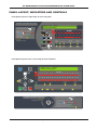
PANEL LAYOUT, INDICATORS AND CONTROLS
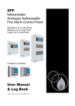
Front panel layout of single loop 16 zone fire panel
Fire Ala rm Con t rol Panel In st ruc t ions
To view more events use the scroll
10:59:03 24 Jun : Normal
FREDCO WAREHOUSING
buttons
To silence the internal sounder: press
Fire
more
information
To silence/resound the alarm sounders:
Turn key to l and press
OR press
and
. Enter code and press
To reset the panel:
Ensure all alarm conditions are silenced and
investigations are complete and press
1
2
3
4
5
6
7
8
9
10
11
12
13
14
15
16
supply
present
test
accessed
general
disablement
phased
evacuation
power
supply
fault
system
fault
sounder
status
delays
running
accept
escape
To exit access mode:
Remove key OR press and hold
silence internal
sounder
General fault
flashing light - call engineer
control panel
reset
silence/resound
sounders
general
fault
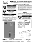
Front panel layout of one or two loop 32 zone fire panel
10:59:03 24 Jun : Normal
FREDCO WAREHOUSING
menu
more information
Fire
silence
internal
sounder
escape
accept
control panel
reset
investigate
silence/resound
sounders
Fire Zones
1
2
3
4
5
6
7
8
9
10
11
12
13
14
15
16
17
18
19
20
21
22
23
24
25
26
27
28
29
30
31
32
supply
present
test
general
fault
Fire Ala r m Cont rol Pa nel I nst ruc t ions
General fault
flashing light - call engineer
general
disablement
accessed
power supply
fault
system
fault
sounder
status
To view more events use the scroll
I
phased
evacuation
delays
running
buttons
To silence the internal sounder: press
O
To silence/resound the alarm sounders:
Turn key to l and press
OR press
and
. Enter code and press
To reset the panel:
Ensure all alarm conditions are silenced and
investigations are complete and press
To exit access mode: Remove key OR press and hold
XFP USER MANUAL & LOG BOOK • Approved Document No. DFU2000510 Rev 1 • Page 6 of 28
XFP NETWORKABLE ANALOGUE ADDRESSABLE FIRE ALARM PANEL
LED Indicators
Liquid crystal display
Provides detailed information on the status of the fire alarm system, see pages 8-11
(General) Fire
Flashes red when there is a fire condition on any zone and goes steady red
when the alarm is silenced. Subsequent fire conditions will restart the general
Fire indicator flashing until it is silenced again
Fire Zones
One or more of these indicators will flash red in an alarm condition to show
which (1-16 or 1-32) zone(s) the fire is in and will go steady when silenced
Supply Present
Normally lit green to show that all of the panel’s power supplies are
functioning correctly
Test
Lit yellow when the panel is in walk test mode. This indicator does NOT light
for any other test condition
Accessed
Lit yellow when the panel is in access level 2 or 3
General Disablement
Lit yellow when one or more zone, sounder, output or relay is disabled
Phased Evacuation
Flashes yellow when there is a phased evacuation in process
General Fault
Flashes yellow when there is a fault condition on the panel. Will always be lit
in conjunction with at least one other Fault indicator
Power Supply Fault
Lit yellow when the panel’s power supply or Mains has failed or the panel’s
standby battery is in poor condition
System Fault
Lit yellow when a system error, such as a microprocessor fault, occurs. Remains
lit even if the panel automatically clears the fault
Sounder Status
Flashes yellow if there is a faulty sounder or a sounder disablement anywhere
on the system
Delays Running
Lit yellow when one or more output delays have been programmed into the panel.
Flashes yellow when one or more output delay is running
Button controls
More Information
Displays additional information on any fire, pre-alarm or fault conditions
that appear on the panel’s display
(Scroll Up) 51
(Scroll Down) 63
Dependent on the status of the panel, these two buttons:
• scroll vertically through any fire, pre-alarm or fault conditions that appear
on the panel’s display
• scroll vertically through the panel’s user menus
• manipulate date, time and disablement settings, etc.
• serve as code input buttons to access levels 2 or 3
Accept 42
Escape 34
Dependent on the status of the panel, these two buttons:
• scroll horizontally through the panel’s user menus
• escape or accept options available in the panel’s user menus
• serve as code input buttons to access levels 2 or 3
Menu
Provides access to the panel’s user menus
Silence Internal Sounder
Silences the panel’s internal sounder
Control Panel Reset
Resets the panel when the sounders are silenced (access levels 2 & 3 only)
Silence / Resound Sounders Silences or resounds the system’s sounders (access levels 2 & 3 only)
Investigate
Starts the panel’s investigate timer function (access levels 2 & 3 only). Only
available if the panel’s investigate function has been enabled by an engineer
Keyswitch control
Turning the keyswitch to the armed position (I) gives the user instant access to
access level 2 (authorised user level)
I
O
XFP USER MANUAL & LOG BOOK • Approved Document No. DFU2000510 Rev 1 • Page 7 of 28
XFP NETWORKABLE ANALOGUE ADDRESSABLE FIRE ALARM PANEL
GENERAL USER OPERATION
(MESSAGES THAT MAY APPEAR ON THE PANEL’S DISPLAY AND WHAT THEY MEAN)
At access level 1, the panel’s display provides feedback on the system’s current status. Priority is always given
to the most important current event, i.e. fire conditions will override pre-alarms and/or fault conditions. This
section (pages 8-11) outlines the various messages that may be displayed, what they mean and what action
is required.
NORMAL CONDITIONS
In normal mode (when no fires, faults or pre-alarms are occurring), one of the following messages will
be displayed at the panel:
Time
Date
System status
24 Jun
: Normal
10:59:34
FREDCO WAREHOUSING
Options
: Normal
: Normal: occupied
: Normal: unoccupied
: Outputs delayed
: Disablements active
: Zone tests active
: Calibrating
Site specific text
Normal is displayed when there are no fires, faults or pre-alarms on the system and the panel’s
day/night (building occupied/unoccupied) facility HAS NOT been set up by the system engineer.
Normal: occupied is displayed when there are no fires, faults or pre-alarms on the system and the panel
is in day (building occupied) mode.
Normal: unoccupied is displayed when there are no fires, faults or pre-alarms on the system and the
panel is in night (building unoccupied) mode.
Day/night (building occupied/unoccupied) settings are normally programmed into the panel by a
system engineer. They allow the system to operate differently dependent on the time of day with, for
example, different detector sensitivity settings and lower sounder volumes. If required, authorised
users can manually alter the time the panel enters day and night mode using the access level 2 menu
options - see pages 14-19.
Outputs delayed is displayed if one or more delays to outputs have been programmed into the panel.
It indicates that certain outputs (which may include sounders, relays and/or output units) will not
trigger in the event of a fire alarm condition for a set period of time, as programmed by the system
engineer. Pressing the More Information button in a fire alarm condition will give more information
about delays.
Disablements active is displayed if one or more disablements have been programmed into the panel
by an authorised user or engineer. If required, you can view these disablements at access level 1 (or, if
you are an authorised user, you can cancel them (or set additional disablements) at access level 2.
Zone tests active is displayed if one or more of the fire alarm system’s zones have been programmed
into test mode by an authorised engineer. When a zone is in test mode, any fire alarm conditions
raised on it WILL NOT be reported to the panel in the normal way. As such, this message should only
appear when an engineer is working on the system. If required, you can view which zones are in test
mode at access levels 1 or 2. Zones can only be taken out of test mode by an authorised engineer.
Calibrating... is displayed if automatic adjustments are taking place to allow the system’s smoke and
heat detectors to perform at their optimum level. Normally, this message only appears at 04:00 hours
although it is possible that an engineer may have programmed this to happen at an alternative time.
Whilst calibrating, the display will list the ID code of the device being calibrated, i.e. “L:1 D:154” and
the system will not return to normal until the process is complete.
XFP USER MANUAL & LOG BOOK • Approved Document No. DFU2000510 Rev 1 • Page 8 of 28
XFP NETWORKABLE ANALOGUE ADDRESSABLE FIRE ALARM PANEL
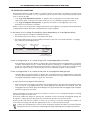
FIRE CONDITIONS
In the event of a fire condition:
•
•
•
•
•
the
the
the
the
the
panel’s general Fire indicator will flash;
panel’s internal sounder (if enabled) will pulse;
relevant Fire Zone indicator on the panel will flash;
panel’s display will show the number and name of the zone in fire (see example below); and
system’s sounders, relays and other output devices will operate as programmed.
Number of zone in fire
Last zone:
Name of zone in fire
1:North Stairs
System status
:FIRE!
1 Zones
Total number of
zones in fire
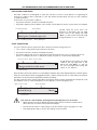
Pressing the More Information button will display the actual device that has triggered the fire
condition, for example:
Number of activated
devices within the zone
Number of zone in fire
If more than one device is in a fire
condition on the zone, the top left
corner of the display will show, for
example “1 of 3” and can be scrolled
through using the 5and6buttons.
1 of 1 Alarms in: Zone 1
North stairs : Detector near exit
Name of zone in fire
Device description
In the event of a fire condition on multiple zones:
• the panel’s general Fire indicator will flash, its internal sounder (if enabled) will pulse and its
relevant Fire Zone indicators will flash;
• the panel’s display will show the first and last zones that went into fire together with the total
number of zones that are in fire. For example, if a fire condition has occurred in zones 1, 2 and 3
in that order, the display will show a message similar to the one below.
• the system’s sounders, relays and other output devices will operate as programmed.
1st Zone: 1: North Stairs
Lastzone: 3: Ground Floor
:FIRE!
3 Zones
To view any additional zones that are in fire, press the 5or6buttons as appropriate. The display will
continue to show the last zone that went into fire but all previous zones will now appear on a stepby-step basis with details of which order they went into fire, i.e. 1st zone, 2nd zone, etc.
Pressing the More Information button at any time will give you details of the actual device(s) that are
in a fire condition on the zone that is on the top line of the display. These can be scrolled through
using the 5and 6buttons.
In the event of a fire condition, the building’s fire management plan should always be
executed.
Authorised users can silence or reset the system as appropriate by entering access level 2 and pressing
the buttons on the panel’s front. Details on how to do this can be found on page 14.
FIRE CONDITIONS WITH OUTPUT DELAYS
If a fire condition occurs on a zone that has been programmed with one or more output delays, the
panel will report the fire condition as described above but the panel’s Delays Running indicator will
flash yellow to indicate that one or more of the zone’s assigned outputs has not yet triggered. Details
of which outputs have delays running can be viewed by pressing the More Information button.
XFP USER MANUAL & LOG BOOK • Approved Document No. DFU2000510 Rev 1 • Page 9 of 28
XFP NETWORKABLE ANALOGUE ADDRESSABLE FIRE ALARM PANEL
1ST-STAGE FIRE CONDITIONS
On sites where there is a high incidence of nuisance alarms or where the consequence of a false alarm
could result in the activation of, say, a sprinkler system, the fire officer may have permitted certain
zones to be set up with:
• a 1st-Stage zone dependency function - to prevent the zone going into full alarm until certain
other events have occurred on the same zone, such as a second device going into alarm; or
• a 1st-Stage investigation delay period - to give the user time to investigate the cause of an
alarm before a full alarm is initiated.
Details of any zones set up with 1st-Stage alarm function will appear on the System Set-Up Data Chart
on page 20, provided it has been completed by the system engineer.
In the event of a 1st-Stage fire condition (zone dependency or investigation delay):
• the panel’s internal sounder (if enabled) will pulse;
• the relevant Fire Zone indicator on the panel will flash;
• the panel’s display will show the number and name of the last zone which entered a “1st-Stage”
fire condition (see example below).
Number of zone in
1st stage fire
Last zone:
Name of zone in
1st stage fire
1:Ground Floor
System status
1st-Stage
1 Zones
Total number of
zones in 1st stage fire
If the 1st-Stage alarm is in a zone set up with a zone dependency function:
Press the More Information button to display the actual device that has triggered the 1st-stage fire
condition (the display will also confirm that the panel is waiting for a confirmatory signal before
going into full alarm). Pressing the More Information again will show how long is left before the
panel auto-resets (returns to normal mode) should a confirmatory signal not be received.
If the 1st-Stage alarm is in a zone set up with an investigation delay period:
Press the More Information button to display the actual device that has triggered the 1st-stage fire
condition (pressing More Information again will count down how long you have to invoke the zone’s
investigation delay period before it goes into full alarm).
To start the zone’s investigation delay period:
Enter access level 2 (see page 14) and press the Investigate button. The period the investigation delay
runs for will be as programmed by the system engineer. Pressing More Information after the
Investigate button has been pressed will display how long is left before the investigation period expires
and the zone goes into full alarm.
If upon investigation you discover the fire condition is correct, you can override the delay by activating
any manual call point in that zone.
Should any additional detection device(s) be activated in the zone being investigated during the
recognition or delay periods, the panel will automatically put the zone into full alarm.
Should you discover the fire condition is false, you can silence or reset the 1st-stage fire condition at
access level 2 (see page 14) and take appropriate action to clear the nuisance alarm.
In effect, the 1st-Stage delay on a zone set up for investigation comprises two delays - the initial recognition
period (where the user is expected to acknowledge the delay) followed by the investigation period itself.
XFP USER MANUAL & LOG BOOK • Approved Document No. DFU2000510 Rev 1 • Page 10 of 28
XFP NETWORKABLE ANALOGUE ADDRESSABLE FIRE ALARM PANEL
PRE-ALARM CONDITIONS
Pre-alarm conditions are designed to warn the user that a smoke or heat detector is registering an
increase in conditions that could lead to a fire. Pre-alarms must be taken seriously as a fire condition
could be imminent.
In the event of a pre-alarm condition:
• the panel’s internal sounder (if enabled) will pulse;
• the panel’s display will show details of the smoke or heat detector which is in pre-alarm, for example:
Pre-alarm message
Panel number
Should there be more than one
detector in pre-alarm, the top right
hand corner of the display will read
‘More. ↑↓’ and can be scrolled through
using the panel’s 5or6 buttons.
Pre-Alarm on: This Panel
North stairs :Detector near exit
Name of zone in pre-alarm
Device description
FAULT CONDITIONS
If a part of the fire alarm system fails due to detector failure, wiring fault, etc.:
• one or more of the panel’s Fault indicators will flash;
• the panel’s internal sounder (if enabled) will pulse;
• the panel’s display will show an appropriate fault message (in the case of a faulty manual call
point, for example, the zone on which the faulty call point is located will be displayed):
Last zone in fault
Name of zone in fault
Zone 1: Ground Floor
There are faults on this zone
More
Should there be more than one fault
condition, the top right side of the
display will read ‘More. ↑↓’ and you
can scroll through them using the
panel’s 5or6 buttons.
Fault message
Press the More Information button to view additional details about the displayed fault. For device specific
faults, the actual device that has triggered the fault condition will be shown. For other faults, information
pertinent to that fault will be displayed instead (if available).
For device specific faults, pressing the More Information button again will display the unique ID code
and address location of the faulty device for the benefit of service engineers, etc.
Name of zone in fault
Device description
Ground Floor :Reception Call Point
More
Device
Missing
D
Device status
In the event of a fault condition, the designated responsible person on site should:
i
• Mute the panel’s internal beeper by pressing the Silence Internal Sounder button.
(Note that any new faults will restart the beeper.)
• Note down the nature of the fault(s) in the Fire Alarm Log Book (pages 21 to 26)
• Take appropriate steps to ensure the fault(s) is/are rectified.
D
XFP USER MANUAL & LOG BOOK • Approved Document No. DFU2000510 Rev 1 • Page 11 of 28
XFP NETWORKABLE ANALOGUE ADDRESSABLE FIRE ALARM PANEL
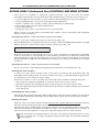
ACCESS LEVEL 1 (General User) CONTROLS AND MENU OPTIONS
Access level 1 is the normal user level which is accessible to everyone. At this level you can:
• Scroll through any fire, pre-alarm and fault conditions (as described on pages 9-11)
• View any disablements or zones that are being tested (if applicable)
• Test the panel’s lamps (its LED indicators and display) to ensure they are working correctly
• Determine the total number of times the panel has been in a fire condition
• Gain entry to access level 2 (authorised user level) and, if you are an engineer, access level 3.
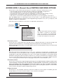
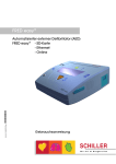
Press the MENU button on the panel’s front at access level 1. The panel’s general user menu is
displayed (see picture below) which can be navigated using the panel’s scroll (56), Accept (4) and
Escape (3) buttons as appropriate.
Each menu option available at access level 1 is explained in detail below.
Menu button
on front of panel
(model dependent)
ENTER ACCESS LEVEL 2
ENTER ACCESS LEVEL 3
DISPLAY FIRE EVENTS
DISPLAY FAULT EVENTS
DISPLAY DISABLEMENTS
DISPLAY ZONES IN TEST
Note that menu options shown in bold will
only appear if relevant to the panel’s
status. For example, the DISPLAY FIRE
EVENTS function will not show if there are
no active fire conditions on the system.
LAMPS TEST
DISPLAY ALARM COUNTER
Enter Access Level 2
Access level 2 is for authorised users only and access to it requires the input of a special four digit code
using the panel’s pushbuttons, or by turning the panel’s keyswitch to the armed position (I).
When the ENTER ACCESS LEVEL 2? prompt appears, press the Accept4button and you will be asked
to enter the code:
Enter Access Level 2 code:
Enter the access level 2 code using the 5(1), 4(2), 6(3), 3(4) buttons as appropriate. The default code
to access level 2 is 3 3 3 3 (four presses of the 6 button). If this does not work, the code may have been
changed by an authorised user/engineer. A record of any changes should appear on the System Set-Up
Data Chart on page 20 of this user manual. If they do not, contact your maintenance company for advice.
As soon as the code has been entered correctly you will be taken into access level 2. Additional panel
controls (see page 14) and menu options (see pages 15-19) will now be available to you.
Enter Access Level 3
Access level 3 is the panel’s engineering/programming level. ON NO ACCOUNT SHOULD ACCESS LEVEL
3 BE ACCESSED BY ANYONE BUT AN AUTHORISED SYSTEM ENGINEER. A FIRE PANEL IS A PIECE OF LIFE
SAFETY EQUIPMENT AND UNAUTHORISED ACCESS MAY AFFECT THE WAY THE PANEL FUNCTIONS,
ENDANGER LIFE AND VOID ITS WARRANTY. If you are an authorised engineer, details of access level 3
can be found in the panel’s separate Engineering manual.
Display Fire Events
This function is only available if there are active fire conditions on the system. If available, press the
Accept4button once and a window similar to the one below will appear:
Last Zone: 1:North Stairs
:Fire!
1 Zone
XFP USER MANUAL & LOG BOOK • Approved Document No. DFU2000510 Rev 1 • Page 12 of 28
XFP NETWORKABLE ANALOGUE ADDRESSABLE FIRE ALARM PANEL
Pressing the 5and6 buttons will scroll the display through all active fire conditions. More detailed
information (if applicable) can be viewed by pressing the panel’s More Information button. To return
to the main access level 1 menu press the Escape3button.
Display Fault Events
This function is only available if there are active faults on the system. If available, press the
Accept4button once and a window similar to the one below will appear:
Zone 1: Ground Floor
There are faults on this zone
Pressing the 5and6buttons will scroll the display through all active faults. More detailed
information (if applicable) can be viewed by pressing the panel’s More Information button. To return
to the main access level 1 menu press the Escape3button.
Display Disablements
This function is only available when there are active disablements on the system. If available, press the
Accept4button once and a window similar to the one below will appear:
1st Zone: 1: Shop floor
On: This Panel: Is Disabled
Pressing the 5and6buttons will scroll the display through all active disablements. More detailed
information (if applicable) can be viewed by pressing the panel’s More Information button. To return
to the main access level 1 menu press the Escape3button.
Display Zones In Test
This function is only available if there are zones being tested. If available, press the Accept4button
once and a window similar to the one below will appear:
Zone 1: North Stairs
Is On Test
Pressing the 5and6buttons will scroll the display through all zones in test mode. More detailed
information (if applicable) can be viewed by pressing the panel’s More Information button. To return
to the main access level 1 menu press the Escape3button.
Testing the Panel’s Lamps
This function tests the panel’s lamps (its LED indicators and display) to ensure they are working correctly.
LAMP TEST?
Display Alarm Counter
AL1
When selected, press the Accept4button and all of the panel’s LED indicators will illuminate steady
for approximately two seconds and its display will progressively block fill. The panel’s internal sounder
(if enabled) will also sound. Upon completion, the panel will return to the main access level 1 menu.
If any of the indicators fail to illuminate or the display does not function correctly, report the fault(s)
to the designated site engineer and make a note of it in the Fire Alarm Log Book (page 21).
Displaying the Panel’s Alarm Counter
This function displays the total number of times the panel has been in a fire alarm condition. When
selected, press the Accept4button once and the display will show the total number of times the panel
has been in a fire condition since it was installed AND the total number of times it has been in alarm
since its alarm counter was last cleared, for example:
Total Alarms = 12
Alarms since 01/01/05 = 7
To return to the main access level 1 menu press the Escape3or Accept4button.
XFP USER MANUAL & LOG BOOK • Approved Document No. DFU2000510 Rev 1 • Page 13 of 28
XFP NETWORKABLE ANALOGUE ADDRESSABLE FIRE ALARM PANEL
ACCESS LEVEL 2 (Authorised User) CONTROLS AND MENU OPTIONS
Access level 2 is available to authorised, trained personnel only. At this level, the panel’s
Silence/Resound Sounders, Control Panel Reset and Investigate buttons become active and you can:
•
•
•
•
•
•
Scroll through any fire, pre-alarm or fault conditions that are displayed on the panel’s display
View any disablements or zones that are being tested (if applicable)
Enable or disable zones, sounders, outputs, relays and devices (as appropriate)
Print, display and/or reset the panel’s event history
Set the time and date
Change the entry code to access level 2 from its factory default.
Details of how to use the panel’s Silence/Resound Sounders, Control Panel Reset and Investigate
buttons can be found below.
Entering access level 2 - USING THE PUSHBUTTONS ON THE PANEL:
Entry to access level 2 requires the input of a special four digit code.
Press the MENU button on the panel’s front at access level 1. When the ENTER ACCESS LEVEL 2? prompt
appears, press the Accept4button and you will be asked to enter the code:
Enter Access Level 2 code:
Enter the access level 2 code using the 5(1), 4(2), 6(3), 3(4) buttons as appropriate. The default
code to access level 2 is 3 3 3 3 (four presses of the 6button). If this does not work, the code may have
been changed by an authorised user/engineer. A record of any changes should appear on the System
Set-Up Data Chart on page 20 of this user manual. If they do not, contact your maintenance company
for advice.
Entering access level 2 - USING THE KEYSWITCH ON THE PANEL:
Entry to access level 2 is gained by turning the panel’s keyswitch to the armed position (I).
Silencing the alarm sounders
To silence any active alarm sounders, enter access level 2 (see above) and momentarily press the
Silence/Resound Sounders button. The alarm sounders will cease to sound and the panel’s general Fire
and relevant Fire Zone indicators will go steady.
Should a fire condition occur on another zone whilst the alarm sounders are silenced, the panel:
• Will sound the sounders programmed for activation by the new zone(s) in alarm
• Will flash its general Fire and appropriate Zone indicator(s) for any new zone(s) in alarm
• May, if programmed, automatically reactivate the silenced alarm sounders and flash any related Fire
Zone indicator(s).
Resounding the alarm sounders
Momentarily pressing the Silence/Resound Sounders button when the alarm sounders are silenced will
resound them. Pressing the Silence/Resound Sounders button again will silence the alarm sounders.
Resetting the panel
After the cause of an alarm has been cleared and the alarm sounders have been silenced (see above),
the panel can be reset by pressing the Control Panel Reset button.
The panel will give a double beep to indicate the reset process has started and, after a few seconds,
the Fire Zone indicators and general Fire indicator will go out to indicate the process is complete. If
there are still any fire conditions on any zones, the panel will go back into alarm as before.
Note that the panel’s Investigate button is only active if an engineer has programmed one or more
zones to operate with a 1st-stage investigation delay period (see page 10 for detailed information
on this feature).
XFP USER MANUAL & LOG BOOK • Approved Document No. DFU2000510 Rev 1 • Page 14 of 28
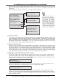
XFP NETWORKABLE ANALOGUE ADDRESSABLE FIRE ALARM PANEL
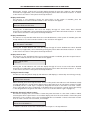
When in access level 2 (see page 14) the panel’s authorised user menu is displayed (see picture below)
which can be navigated using the panel’s scroll (56), Accept(4) and Escape (3) buttons as
appropriate.
Each menu option available at access level 2 is explained in detail below.
DISPLAY ALARM COUNTER
ENTER ACCESS LEVEL 3
Clear to todays date?
DISPLAY FIRE EVENTS
DISPLAY FAULT EVENTS
DISPLAY DISABLEMENTS
DISPLAY ZONES IN TEST
LAMPS TEST
DISPLAY ALARM COUNTER
PRINT EVENT HISTORY?
DISPLAY EVENT HISTORY?
RESET EVENT HISTORY?
SET TIME/DATE
EVENT LOG FUNCTIONS
SET/CLEAR DISABLEMENTS
ENABLE/DISABLE ZONES
CHANGE ACCESS LEVEL 2 CODE
ENABLE/DISABLE SOUNDERS
The menu options shown in
bold will only appear if
relevant to the panel’s status.
For example, the DISPLAY
FIRE EVENTS function will not
show if there are no active
fire conditions on the system.
If any of these bold menus
appear, refer to their listings
in access level 1 (pages 12-13)
for details of how they work.
ENABLE/DISABLE OUTPUTS
ENABLE/DISABLE RELAYS
ENABLE/DISABLE DEVICES
ENABLE/DISABLE FAULT RELAY
ENABLE/DISABLE OUTPUT DELAYS
Enter Access Level 3
Access Level 3 is the panel’s engineering/programming level. ON NO ACCOUNT SHOULD ACCESS LEVEL
3 BE ACCESSED BY ANYONE BUT AN AUTHORISED SYSTEM ENGINEER. A FIRE PANEL IS A PIECE OF LIFE
SAFETY EQUIPMENT AND UNAUTHORISED ACCESS MAY AFFECT THE WAY THE PANEL FUNCTIONS,
ENDANGER LIFE AND VOID ITS WARRANTY. If you are an authorised engineer, details of access level 3
can be found in the panel’s separate Engineering manual.
Testing the Panel’s Lamps
This function tests the panel’s lamps (its LED indicators and display) to ensure they are working correctly.
When selected, press the Accept4button and all of the panel’s LED indicators will illuminate steady
for approximately two seconds and its display will progressively block fill. The panel’s internal sounder
(if enabled) will also sound. Upon completion, the panel will return to the main access level 2 menu.
If any of the indicators fail to illuminate or the display does not function correctly, report the fault(s)
to the designated site engineer and make a note of it in the fire system’s log book.
Displaying and Clearing the panel’s alarm counter
This function displays the total number of times the panel has been in a fire alarm condition. When
selected, press the Accept4button and the display will show the total number of times the panel
has been in a fire condition since it was installed AND the total number of times it has been in alarm
since its alarm counter was last cleared, for example:
Total Alarms = 12
Alarms since 01/01/05 = 7
Press the Escape3button to return to the main access level 2 menu or, to clear the alarm counter,
press the Accept4button. A window similar to the one overleaf will appear:
Clear to today's date?
Alarm since 01/01/05 = 7
Press the Accept4button once and the alarm counter will reset and start counting any new fire
conditions from today’s date (assuming that the date programmed into the panel is today’s date). A
short confirmation message will confirm the change has been made before the display returns to the
main access level 2 menu.
XFP USER MANUAL & LOG BOOK • Approved Document No. DFU2000510 Rev 1 • Page 15 of 28
XFP NETWORKABLE ANALOGUE ADDRESSABLE FIRE ALARM PANEL
Changing the panel’s time and date
This function allows the panel’s time and date to be adjusted. When selected, press the Accept4
button and the following window (or similar) will appear:
Set the time:- 00:00
Use the 5and6buttons to adjust the hour (the panel has a 24 hour clock so hours 0 to 23 are available).
When the correct hour is displayed, press the Accept4button to move to the minutes field.
Use the 5and4buttons to adjust the minutes.
When the correct time is displayed, press the Accept4button to alter the date.
A window similar to the one below will appear:
Set the time:- 16:52
Set the date:- xx:xx:xx
Use the scroll 56 and Accept4buttons to set the day/month/year as appropriate. When correct,
press the Accept4button again and you will be returned to the main access level 2 menu.
Event log functions
This function allows you to print a hard copy of the panel’s event log to an external printer (if connected),
to view it on the panel’s display or to reset it. When the EVENT LOG FUNCTIONS? prompt appears, press
the Accept 4button and scroll down to the desired event log function using the 6button.
The PRINT EVENT HISTORY function, when selected, will print the panel’s log to a printer. When
selected, the following window will appear:
Printing Event 56...
Press ESC to stop printing
Note: Print Event History function is only
available on the 1 or 2 Loop, 32 Zone Version.
If you try to print the event history when no printer is connected, the following window will appear:
Printer fault, Check connections, paper
Ensure the printer is on-line
To escape from this window, press the
Control Panel Reset button.
The DISPLAY EVENT HISTORY menu option, when selected, displays the panel’s 500 event log on the
display. For example:
Event 499 at 05/02/05 11:31:19
Access Level 2 entered
Initially only the last event will appear in the window but you can scroll through the list using the
5button to see previous saved events. When the log is full, the oldest record is replaced by the
newest record. Events are listed in chronological order. When you have finished viewing the required
events, press the Escape 3button to return to the previous menu.
The RESET EVENT HISTORY? menu option, when selected, clears the log from the panel’s memory. To
help ensure it is not erased by mistake, a warning will appear when the Accept4button is pressed:
Are you sure you want to erase
the Event log?
Press the Accept4button to confirm you want to erase the log. The following window will appear
whilst the log resets after which the panel will return you to the EVENT HISTORY MENU.
Resetting the Event History...
Resetting entry 499
XFP USER MANUAL & LOG BOOK • Approved Document No. DFU2000510 Rev 1 • Page 16 of 28
XFP NETWORKABLE ANALOGUE ADDRESSABLE FIRE ALARM PANEL
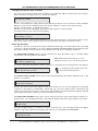
Disabling or enabling parts of the system
Selecting this menu option takes you to the disablements sub-menu which allows you to enable or
disable zones, sounders, outputs, relays, individual devices and/or the panel’s fault relay.
We strongly recommend all disablements are regularly reviewed and immediately enabled when no
longer necessary as they can have a major effect on how the system works.
ENABLE/DISABLE ZONES
This function allows you to disable zones from reporting faults, fires, pre-alarms, etc., and is normally
used to temporarily disable a zone of detectors/call points in areas such as loading bays where they are
prone to nuisance triggering from vehicle fumes. When selected, press the Accept4button and a
window similar to the one below will appear:
Zone: 1: Shop Floor
Enabled
Select the zone to be disabled/enabled using the 5and6 buttons. Press the Accept4button and the
zone’s status (Enabled or Disabled) will flash. Next, use the 5and6 buttons to toggle between
enabled and disabled and press the Accept4button to select the desired option.
The window will now move to the next available zone allowing further enablements or disablements
to be made. Alternatively, to return to the previous menu press the Escape3button.
Please note: if all the input devices on a zone have been individually disabled using the ENABLE/DISABLE
DEVICES function described on page 18, the zone they belong to will also be disabled. If you try to reenable a zone which has no enabled devices on it, a prompt appears saying this cannot be done.
Instead you must first enable at least one device on the zone using the ENABLE/DISABLE DEVICES
function before re-enabling the zone itself.
ENABLE/DISABLE SOUNDERS
This function allows you to disable one or more sounder groups from sounding in a fire condition.
When selected, press the Accept4button and a window similar to the one below will appear:
Sounder Group: 1
Select the sounder group (1 to 16 or ALL) to be disabled/enabled using the
5and6 buttons.
When the desired sounder group has been selected, press the Accept4button once and the sounder
group’s status (Enabled or Disabled) will flash. Next, use the 5and6 buttons to toggle between
enabled and disabled and press the Accept4button to select the desired option. The window will now
move to the next sounder group allowing further enablements or disablements to be made.
Alternatively, to return to the previous menu press the Escape3button.
ENABLE/DISABLE OUTPUTS
This function allows you to disable one or more output sets from sounding in a fire condition. It is typically
used to disable, for example, auto-diallers and other ancillary equipment from activating during routine
maintenance. When selected, press the Accept4button and a window similar to the one below will appear:
Output Set: 1
Select the output set (1 to 16 or ALL) to be disabled/enabled using the
5and6 buttons.
When the desired output set has been selected, press the Accept4button once and the output set’s
status (Enabled or Disabled) will flash. Next, use the 5and6 buttons to toggle between enabled and
disabled and press the Accept4button to select the desired option. The window will now move to the
next output set allowing further enablements or disablements to be made. Alternatively, to return to
the previous menu press the Escape3button.
XFP USER MANUAL & LOG BOOK • Approved Document No. DFU2000510 Rev 1 • Page 17 of 28
XFP NETWORKABLE ANALOGUE ADDRESSABLE FIRE ALARM PANEL
ENABLE/DISABLE RELAYS
This function allows the disablement of one or more of the panel’s 3 auxiliary relays from activating as
programmed. When selected, press the Accept4button and a window similar to the one below will appear:
Panel Relay:- 1
Select the relay (1, 2 or 3) to be disabled/enabled using the 5and 6 buttons.
When the desired relay has been selected, press the Accept4button and the relay’s status (Enabled or
Disabled) will flash. Next, use the 5and6 buttons to toggle between enabled and disabled and press
the Accept4button to select the desired option. The window will now move to the next relay
allowing further enablements or disablements to be made. Alternatively, to return to the previous
menu press the Escape3button.
ENABLE/DISABLE DEVICES
This function allows loop devices to be disabled from reporting faults, fires, pre-alarms, etc., and is
normally used to temporarily disable detectors/call points that are nuisance tripping. When selected,
press the Accept4button and a window similar to the one below will appear:
Select Zones:- 1: Shop Floor
Use the 5and6 buttons to select the zone where the device you wish to disable/enable is located.
When selected, press the Accept4button and a list of all devices that can be disabled or enabled in
that zone will appear, e.g.
Shop Floor:- 1: Gent WC
Loop 1, Device 3: Enabled
Use the 5and6 buttons to scroll through the available devices. When the desired device appears,
press the Accept4button and the device’s status (Enabled or Disabled) will flash. Next, use the
5and6 buttons to toggle between enabled and disabled and press the Accept4button to select the
desired option. The window will now move to the next device allowing further enablements or
disablements to be made. Alternatively, to return to the previous menu press the Escape3button.
Please note: if all the input devices on a zone are individually disabled, the zone they belong to will also
be disabled. If you try to re-enable a zone which has no enabled devices on it using the ENABLE/DISABLE
ZONES function described on page 17, a prompt appears saying this cannot be done. Instead you must
first enable at least one device on the zone before re-enabling the zone itself.
ENABLE/DISABLE FAULT RELAY
This function can be used to suppress the panel’s fault relay from activating in a fault condition. When
selected, press the Accept4button and the following window will appear:
Fault relay is:- Enabled
Use the 5and6 buttons to toggle between enabled and disabled and press the Accept4button to
select the desired option. Alternatively, to return to the previous menu press the Escape3button.
ENABLE/DISABLE OUTPUT DELAYS
This function can be used to globally disable or enable any delays to outputs that have been programmed
into the panel. When selected, press the Accept4button and the following window will appear:
Delays to Outputs are:Enabled
Use the 5and6 buttons to toggle between enabled and disabled and press the Accept4button to
select the desired option. Alternatively, to return to the previous menu press the Escape3button.
XFP USER MANUAL & LOG BOOK • Approved Document No. DFU2000510 Rev 1 • Page 18 of 28
XFP NETWORKABLE ANALOGUE ADDRESSABLE FIRE ALARM PANEL
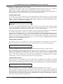
Changing the access level 2 entry code
This function allows you to change the four digit code needed to activate the panel’s access level 2
menu options. When selected, press the Accept6 button and the following window will appear:
Enter NEW Access Level 2 Code
Using the 5(1), 4(2), 6(3),3(4) buttons, enter the new four digit access level 2 entry code. After the
fourth digit has been entered, the panel will request you confirm the new code by re-entering it.
Enter NEW Access Level 2 Code: ****
Confirm NEW Access Level 2 Code:
Enter the code again by pressing the 5(1), 4(2), 6(3), 3(4) buttons in same sequence. If the two
codes match, the panel will accept the code and you will be taken back to access level 2. If you type
an incorrect confirmation code you will be prompted to start the new code entry sequence again.
BE SURE TO KEEP A RECORD OF THE NEW CODE ON PAGE 20 OF THIS USER MANUAL.
XFP USER MANUAL & LOG BOOK • Approved Document No. DFU2000510 Rev 1 • Page 19 of 28
XFP NETWORKABLE ANALOGUE ADDRESSABLE FIRE ALARM PANEL
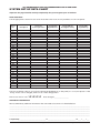
SYSTEM SET-UP DATA CHART
Important: this page should be carefully completed by the system engineer prior to handover.
ZONE FUNCTIONS
Tick the appropriate column for each zone. Note that zones 17-32 are only available on 1-32 zone panels.
Zone
No.
Zone
description
Set up for
normal operation
Set up with
dependencies
Set up with an
investigate facility
Set up with
output delays
1
2
3
4
5
6
7
8
9
10
11
12
13
14
15
16
17
18
19
20
21
22
23
24
25
26
27
28
29
30
31
32
ACCESS LEVEL 2 (AUTHORISED USER) CODE
The factory default code for access level 2 (using the pushbuttons on the panel) is 3 3 3 3 (four presses of the
6key). If this code is changed, make a note of the changes here:
New access level 2 code
❑❑❑❑
Date changed __________________
ADDITIONAL INFORMATION
We recommend any additional information the user needs to be aware of is detailed below:
_________________________________________________________________________________________________________
_________________________________________________________________________________________________________
_________________________________________________________________________________________________________
_________________________________________________________________________________________________________
_________________________________________________________________________________________________________
Completed by ____________________________________ of ______________________________________ on ____ / ____ / ____
XFP USER MANUAL & LOG BOOK • Approved Document No. DFU2000510 Rev 1 • Page 20 of 28
XFP NETWORKABLE ANALOGUE ADDRESSABLE FIRE ALARM PANEL
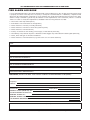
FIRE ALARM LOG BOOK
It is recommended that this log book be maintained by a responsible person, who should ensure that every entry
is properly recorded. In the UK, this is necessary to satisfy the recommendations of BS5839-1, compliance with
which may be a requirement of legislation. If your premises are certificated under the Fire Precautions Act 1971,
failure to keep a suitable log book may be a breach of the requirements of the certificate, which is a criminal
offence. In order to satisfy the requirements of BS5839-1 the following must be recorded:
•
•
•
•
•
•
•
•
•
The name of the responsible person;
Brief details of the maintenance arrangements;
Dates and times of all tests, including fire drills;
Dates and times of all fires to which the system responds;
Dates and times of all false alarms;
Causes, circumstances surrounding, and category of false alarms (if known);
The identity of any manual call point or fire detector that triggers any of the above fire alarm signals (if known);
Dates, times and type of all faults and defects.
Dates and times of all maintenance (e.g service visit or non-routine attention).
USER:
SITE ADDRESS:
RESPONSIBLE PERSON(S) ON SITE:
THE SYSTEM WAS DESIGNED BY:
THE SYSTEM WAS INSTALLED BY:
THE SYSTEM WAS COMMISSIONED BY:
THE SYSTEM WAS ACCEPTED BY:
VERIFICATION WAS UNDERTAKEN BY:
FOR SERVICE (DETAILS OF WHO YOU SHOULD CONTACT IF MAINTENANCE IS REQUIRED)
THE SYSTEM IS MAINTAINED UNDER CONTRACT BY:
Company:
Address:
Contact No:
Expiry Date:
NORMAL HOURS (MON-FRI) TEL:
OUTSIDE NORMAL HOURS TEL:
MANNED CENTRE TEL:
MANNED CENTRE CODE:
THE NORMAL MAXIMUM ATTENDANCE TIME FOR A MAINTENANCE TECHNICIAN IS:
EXPENDABLE COMPONENT REPLACEMENT PERIODS (LIST):
XFP USER MANUAL & LOG BOOK • Approved Document No. DFU2000510 Rev 1 • Page 21 of 28
XFP NETWORKABLE ANALOGUE ADDRESSABLE FIRE ALARM PANEL
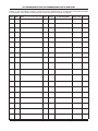
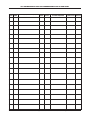
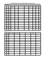
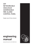
Details of tests (including fire drills), actual fire alarms, disablements or enablements and faults should be
recorded here. False alarms and maintenance work should be recorded on page 26.
DATE TIME EVENT
e.g. test, fire alarm signal, fault
ZONE DEVICE
ACTION REQUIRED
COMPLETED INITIALS
XFP USER MANUAL & LOG BOOK • Approved Document No. DFU2000510 Rev 1 • Page 22 of 28
XFP NETWORKABLE ANALOGUE ADDRESSABLE FIRE ALARM PANEL
DATE TIME EVENT
e.g. test, fire alarm signal, fault
ZONE DEVICE
ACTION REQUIRED
COMPLETED INITIALS
XFP USER MANUAL & LOG BOOK • Approved Document No. DFU2000510 Rev 1 • Page 23 of 28
XFP NETWORKABLE ANALOGUE ADDRESSABLE FIRE ALARM PANEL
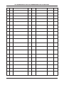
DATE TIME EVENT
e.g. test, fire alarm signal, fault
ZONE DEVICE
ACTION REQUIRED
COMPLETED INITIALS
XFP USER MANUAL & LOG BOOK • Approved Document No. DFU2000510 Rev 1 • Page 24 of 28
XFP NETWORKABLE ANALOGUE ADDRESSABLE FIRE ALARM PANEL
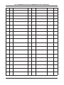
DATE TIME EVENT
e.g. test, fire alarm signal, fault
ZONE DEVICE
ACTION REQUIRED
COMPLETED INITIALS
XFP USER MANUAL & LOG BOOK • Approved Document No. DFU2000510 Rev 1 • Page 25 of 28
XFP NETWORKABLE ANALOGUE ADDRESSABLE FIRE ALARM PANEL
False alarms
DATE
TIME
DEVICE THAT
FINDINGS OF CATEGORY FURTHER DONE
BRIEF CIRCUMSTANCES MAINTENANCE
CAUSE
ACTION PLEASE
ZONE TRIGGERED THE
(where cause is unknown, VISIT REQUIRED? MAINTENANCE OF FALSE
(IF KNOWN) record activities in the area)
ALARM SIGNAL
(YES or NO)
TECHNICIAN
ALARM REQUIRED TICK
Maintenance work
DATE
TIME
ZONE
DEVICE
REASONS FOR WORK WORK CARRIED OUT
(WHERE APPLICABLE) (WHERE APPLICABLE)
FURTHER WORK
REQUIRED
XFP USER MANUAL & LOG BOOK • Approved Document No. DFU2000510 Rev 1 • Page 26 of 28
SIGNATURE
XFP NETWORKABLE ANALOGUE ADDRESSABLE FIRE ALARM PANEL
BS5839-1 recommends that certificates be issued for all aspects of the fire alarm system including design,
installation, commissioning, acceptance, verification (optional) and maintenance. Therefore, before this user
manual is handed over, the following installation certificate and the commissioning certificate (overleaf) should
be completed as appropriate by the relevant installation/commissioning engineer(s). Please ensure that the
System Set-Up Data Chart on page 20 and the relevant parts of the Fire Alarm Log Book on page 21 are also
completed as appropriate. For countries outside the UK, different certification requirements may apply.
Certificate
of INSTALLATION
for the fire alarm system at:
Address:
I/we being the competent person(s) responsible (as indicated by my/our signatures below) for the installation of
the fire alarm system, particulars of which are set out below, CERTIFY that the said installation for which I/we have
been responsible complies to the best of my/our knowledge and belief with the specification described below and
with the recommendations of Section 4 of BS5839-1, except for the variations, if any, stated in this certificate.
Name (in block letters):
Position (in block letters):
Signature:
Date:
For and on behalf of:
Address & postcode:
The extent of the liability of the signatory is limited to the system described below.
Extent of installation work covered by this certificate:
Specification against which the system was installed:
Variations from the specification and/or Section 4 of BS5839-1 (see BS5839-1, Clause 7):
Wiring has been tested in accordance with the recommendations of Clause 38 of BS5839-1.
Test results have been recorded and provided to:
Unless supplied by others, the “as fitted” drawings have been supplied to the person responsible for
commissioning the system {see Clause 36.2m) of BS5839-1:
XFP USER MANUAL & LOG BOOK • Approved Document No. DFU2000510 Rev 1 • Page 27 of 28
XFP NETWORKABLE ANALOGUE ADDRESSABLE FIRE ALARM PANEL
BS5839-1 recommends that certificates be issued for all aspects of the fire alarm system including
design,installation, commissioning, acceptance, verification (optional) and maintenance. Therefore, before this
user manual is handed over, the following commissioning certificate and the installation certificate (overleaf)
should be completed as appropriate by the relevant installation/commissioning engineer(s). Please ensure that
the System Set-Up Data Chart on page 20 and the relevant parts of the Fire Alarm Log Book on page 21 are also
completed as appropriate. For countries outside the UK, different certification requirements may apply.
Certificate
of COMMISSIONING
for the fire alarm system at:
Address:
I/we being the competent person(s) responsible (as indicated by my/our signatures below) for the commissioning of the fire
alarm system, particulars of which are set out below, CERTIFY that the said work for which I/we have been responsible complies
to the best of my/our knowledge and belief with the specification described below and with the recommendations of Clause
39 of BS5839-1, except for the variations, if any, stated in this certificate.
Name (in block letters):
Position (in block letters):
Signature:
Date:
For and on behalf of:
Address & postcode:
The extent of the liability of the signatory is limited to the system described below.
Extent of system covered by this certificate:
Variations from the recommendations of Clause 39 of BS5839-1 (see BS5839-1, Clause 7):
❏
❏
❏
❏
All equipment operates correctly
Installation work is, as far as can be reasonably ascertained, of an acceptable standard.
The entire system has been inspected and tested in accordance with the recommendations of 39.2c of BS5839-1.
❏
The system performs as required by the specification prepared by:
a copy of which I/we have been given.
Taking into account the guidance contained in Section 3 of BS5839-1, I/we have not identified any obvious potential for
an unacceptable rate of false alarms.
❏
The documentation described in Clause 40 of BS5839-1 has been provided to the user.
The following work should be completed before/after (delete as applicable) the system becomes operational:
The following potential cause(s) of false alarms should be considered at the time of the next service visit:
Before the system becomes operational, it should be soak tested in accordance with the recommendations of 35.2.6 of BS5839-1
for a period of: _____________ (enter a period of either one week, such period as required by the specification, or such period as
recommended by the signatory of this certificate, whichever is the greatest, or delete if not applicable).
XFP USER MANUAL & LOG BOOK • Approved Document No. DFU2000510 Rev 1 • Page 28 of 28