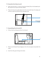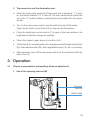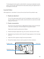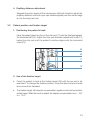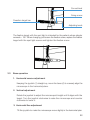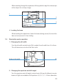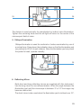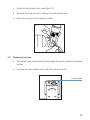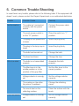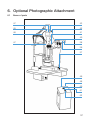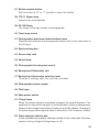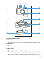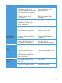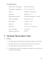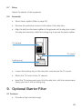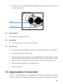
1
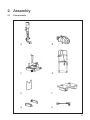
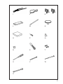
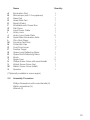
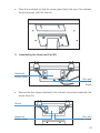
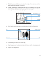
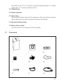
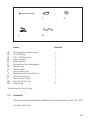
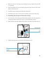
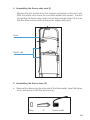
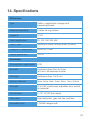
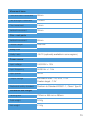
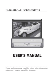
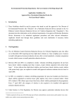
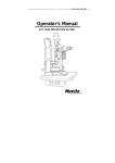
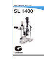
USER’S MANUAL SLIT LAMP
SL 1400
Notification
Dear Users,
Thank you for your purchase of SL 1400 Slit Lamp. Please take time to read our
user’s manual carefully before use.
This guarantees you to make full use of this unit and prolongs the operation life of
this unit.
Precautions
If you have detected abnormal heat, smoke, noise or smell, immediately stop using
the product.
In the event of an abnormality, turn off the power and disconnect the power plug from
the power socket. Continuing to use the product may result in electric shock or fire.
Observe the instructions given below regarding the power cable:
•
•
•
•
•
•
Be sure to use the supplied or specified power cable.
Do not modify, forcibly bend, kink or pull the power cable.
When disconnecting the power cable from the AC outlet, be sure to hold the cable
by the plug.
Pulling the cable may cause wire breakage or shot circuit, resulting in fire or electric
shock.
Do not connect or disconnect the plug of the power cable to/from the AC outlet
using wet hands.
Doing so may result in electric shock.
Do not touch the product with wet hands while the power cable is connected
to the AC outlet.
Doing so may result in electric shock.
If the product will not be used for a long period, disconnect the power cable
from the power source. Leaving the cable connected to the power socket for
a prolonged period will consume electricity and may result in heating.
Content
1.
Name of Parts............................................................................................... 4
2.
Assembly....................................................................................................... 8
3.
Operation.................................................................................................... 19
4.
Maintenance............................................................................................... 28
5.
Common Trouble Shooting......................................................................... 35
6.
Optional Photographic Attachment............................................................. 37
7.
Optional Observation Tube.......................................................................... 65
8.
Optional TV Accessories............................................................................. 67
9.
Optional Barrier Filter.................................................................................. 68
10. Applanation Tonometer................................................................................ 69
11. 12.5x measuring eyepieces......................................................................... 70
12. Resopnsibility............................................................................................... 71
13. Transportation............................................................................................. 71
14. Specifications.............................................................................................. 72
1. Name of Parts
24
25
23
26
22
27
21
28
19
29
20
30
18
31
17
32
16
33
15
34
14
35
12
36
13
1
11
2
10
3
9
4
8
5
7
6
4
1. Joystick
Incline joystick slightly to move the instrument in the horizontal plane and
rotate it to adjust the elevation of the microscope.
2. Base Locking Screw
The base will be locked when this screw is tightened.
3. Rail Cover
Protects the rail surface
4. Base
Supports the microscope and the illumination arms with the joystick controlling
its movement.
5. Work Table
6. Accessory Drawer
Stores the focusing test rod and other accessories.
7. Brightness Control Switch
Two levels are available – H (HIGH), N ( NORMAL). Avoid working continuously
at the high setting, as the service life of the bulb will be shortened.
8. Main Power Switch
9. Pilot Lamp
10. Microscope Arm Locking Knob
Prevents rotational movement of the microscope arm.
11. Angle Mark Ring
Marks on the angle mark ring of the illumination arm align to the long mark
on the microscope arm. When 0 on the ring aligns to the short mark at one
side of the user, the right eyepiece may be obstructed, and the side of the
patient the left eyepiece.
12. Chin-rest Elevation Adjustment Knob
Rotate the knob to adjust the elevation of the chinrest.
13. Location Roller
When the roller is in the middle, the included angle between the microscope
arm and the illumination arm is 0º, when it is to the right or left the included
angle is 10º.
5
14. Microscope and Illumination arm Coupling Bolt
Tightening this bolt permits the illumination arm and the microscope arm
to be rotated simultaneously. Loosening the bolt allows the illumination arm
and microscope arm to rotate separately.
15. Hruby Lens Guide Plate
The plate is also used for the applanation tonometer.
16. Microscope Fixation Screw
17. Chin-Rest
18. Magnification Select Dial
Five magnifications are provided.
19. Prism Boxes
The prism boxes are used to adjust the interpupillary distance.
20. 12.5x Eyepiece
Before use, adjust the diopter ring for each eyepiece to get a clear image.
21. Microscope Fixation Screw
22. Accessory Mount
The accessory mount will accept the Model R-900 Goldmann applanation
tonometer in addition to other accessories.
23. Horizontal Mark
The horizontal center of the patient’s eye is aligned to the mark by changing
the elevation of the microscope using the joystick.
24. Forehead Belt
25. Diffusion Lens
The diffusion lens is used for photographing at low magnifications and for
enlarging the field of magnification.
26. Lamp Cap
27. Aperture height and display window
28. Filter Selection Lever
There are four filter selections.
6
29. Aperture and Slit Height Control Knob
Rotate this knob to adjust the spot and the slit height. Turn the knob
horizontally to rotate the slit.
30. Fixation Target
An illuminated fixed spot for patient to look at.
31. Reflecting Mirror
Both long and short reflecting mirrors are provided.
The long mirror is used for most examination procedures.
The short mirror is used when the long mirror interferes with the optical path
as may happen a during funduscopy.
32. Hruby Lens
Used for observation of fundus and the posterior segment of the vitreous
body.
33. Hruby Lens Holder
34. Centering Knob
Loosening the knob allows the illumination light to be moved from the center
of the field of vision for indirect retro-illumination. Tightening the knob brings
the illumination light back to the center.
35. Slit Width Control Knob
The slit width is continuously adjustable from 0 to 9mm.
7
2. Assembly
2.1
Components
A
B
C
D
E
F
G
H
8
I
J
K
L
M
N
O
P
Q
R
S
T
U
V
W
X
9
A
B
C
D
E
F
G
H
I
J
K
L
M
N
O
P
Q
R
S
T
U
V
W
X
Name
Quantity
Illumination Part
Microscope (with 10x eyepieces)
Base Part
Head-Rest Part
Breath Shield
Worktable with Power Box
Rail Cover
Input Power Cable
Hruby Lens
Hruby Lens Guide Plate
Spare Main Illumination Bulb
Chin-Rest Paper
Focusing Test Rod
Protection Cap
Dust-Proof cover
Fixation Target
Spare Long Reflecting Mirror
Spare Short Reflecting Mirror
Brush
Spare Fuse
Phillips Screw Driver with wood handle
Watch Screw Driver (big)
Watch Screw Driver (small)
Spanner
1
1
1
1
1
2
1
1
1
2
1
1
1
1
1*
1
1
1
1
2
1
1
1
1
(*Optionally available in some region)
2.2
Assembly Procedure
Phillips Screwdriver with wood handle (U)
Watch screwdriver (V)
Wrench (X)
10
1. Selecting voltage and fuse
Fuse holder
Voltage
selector
Selector voltage and fuse
•
Check the setting on the voltage selector located on the bottom of the power
box. If it doesn’t match with the input voltage, slide it to the proper position
with screwdriver (V).
•
Open the fuse holder with screw driver (U) and take out the fuse, ensure that
its rated value corresponds to the mains voltage:
110 Volt.....................1A
220 Volt.....................0.5A
The 220 V- 0.5 A is installed by the factory.
Important Matters
Set the input voltage and frequency of the instrument according to that of the mains.
2. Assembling the worktable (F)
•
To attach the worktable on the LSL1400 motorized instrument table, please
unscrew the four M8x20mm bolts with spring washers with the wrench (X).
•
Align the worktable screw hole to the assembly hole of the instrument table.
11
•
3.
Place the worktable so that the power panel faces the user, then refasten
the bolt securely with the wrench.
Assembling the Head-rest Part (D)
Head rest
fixation plate
Chin rest
connection
board
•
Remove the four screws attached to the chinrest connection board with the
screw driver (U).
Screw
Head rest
fixation plate
Chin rest
connection board
12
•
Put two cables in the gap between the headrest fixation plate and the chinrest connection board.
•
While ensuring the cables are not compressed, retighten the previously
removed screws.
4. Assembling the base part (C) and the rail covers (G)
Wheel
Rail
•
Place the wheels of both sides of the base (C) on the rails on the worktable
•
Check whether the wheels can be rolled smoothly on the rails.
•
Remove the four screws attached to the rail with the screw driver (W).
•
Place the rail cover (G) to the rail and retighten the previously removed screws.
Mark
Shaft sleave
Limiting board
13
5. Assembling Illumination part (A)
•
Loosen the illumination arm bolt (13).
13
•
Rotate the brass shaft sleeve to make the angle of the red mark and the
illumination arm between 30º and 90º.
•
Loosen the screw on the illumination arm with the screwdriver (V). Align the
assembly hole of the illumination arm to the brass shaft sleeve and lower
carefully, while simultaneously aligning the two red marks.
Illumination arm
Mark
Screw
•
After the two red marks are accurately aligned, retighten the screw.
B
Fixing screw
Groove
6.
Pin
Assembling the binocular tubes (B)
•
Align the groove on the binocular tubes with the pin on the microscope body.
•
Tighten the fixing screw.
14
7. Assembling the breath shield (E)
Important Matters
Avoid touching any lens surface while assembling the breath shield (E).
•
Remove the breath shield fixation screw from the microscope arm.
•
Pass the removed screw through the hole of the breath shield then re-screw
it into the arm.
Microscope arm
Fixing screw
Breath shield
8. Removing the illumination part shipping pad
•
This pad is used to protect the slit mechanism of the illumination part during
shipping.
•
Remove the rubber band and gently pull the pad out.
Rubber band
Pad
15
9.
•
Connecting Plug
Remove the sticky shipping tape from the cap. The tape ensures that the
cap is remains fastened to the lamp base during transportation.
Sticky tape
•
Insert the plug on the top of the headrest part (D) into the socket of the lamp
cap (26) on the illumination part (A).
•
Connect the two plugs below the headrest part with the corresponding output
sockets of the power box.
•
Insert the plug of the input power cable (H) into the input socket of the power
box.
H
Cable clip
•
Remove the cable clips from the bottom of the worktable with screwdriver
(U) and route the output and input cables through them, then re-attach them
to the bottom of the worktable.
16
10. Assemble the Hruby Lens (I)
•
Insert the Hruby lens ( I ) into the Hruby lens holder (26) on the headrest part.
Be careful not to touch the lens surface.
•
Place the Hruby lens guide plate (J) into the main shaft hole of the base part
with the small end pointed at the headrest part.
I
Hruby lens
holder
11. Assembling the chin-rest (E)
•
Pull out the two fixing pins from the chinrest.
J
•
Remove and discard the packaging for the chin-rest paper and position the
paper.
•
Insert the fixing pins through the holes.
17
H
Pin
12. Storing spare parts
Spare parts may be stored in the accessory drawer.
6
2.3
Inspection procedure after assembly
1. Power plug
•
This instrument supplied with a 3-wire grounded line cord. Do not remove
or disconnect the ground. Please select proper power sockets and plugs
•
Always ensure that the instrument is well grounded.
Important Matters
Please use the special cable supplied with this instrument.
18
2. The power box and the illumination part
•
When the main power switch (8) of the power box is placed at “1” it turns
on, and when located at “0” it turns off. The main power switch should be
set to the “0” position before connecting the input cable with the power
socket.
•
Turn on the main power switch, and the pilot lamp (9) will illuminate.
Open the slit width control knob (35) to examine the illumination.
•
Press the brightness control switch (7) in each of the two positions, the
brightness should be change accordingly.
•
Check the fixation target device to confirm it is lit.
•
Check that all the movable parts such as aperture and slit height control knob
(29), filter selection lever (28), and magnification lever (18), etc. move freely.
•
After inspection, turn off the main power and cover the instrument with the
dust cover (O).
3. Operation
3.1
Diopter compensation and pupillary distance adjustment.
1. Use of the focusing test rod (M)
Focusing
test rod
Shaft holder
19
The focusing test rod is used to confirm that the microscope is adjusted correctly.
Insert it into the main shaft hole with the flat surface facing the objective lens in
the direction of the user.
Important Matters
After adjustment, remember to remove the rod and insert the protective cap.
2. Brightness adjustment
Turn on the main power switch and set the brightness control switch (7) at
the “N” position. Turn the slit width control knob (35) to make the slit width
between 2 and 3mm.
3. Diopter compensation
The focus of the microscope is calibrated according to the emmetropia.
If the user is ametropic, he should adjust the eyepiece diopter.
Adjustment should be performed as follows:
•
Rotate the diopter adjustment ring (19) counter clockwise until it stops.
•
Rotate the ring clockwise until a sharp slit image appears on the focusing
test rod.
•
Adjust the other eyepiece using the same procedure.
•
Record the diopter value on each eyepiece for future reference.
Diopter scale
Prism box
Adjustment ring
20
4. Pupillary distance adjustment
Separate the prism boxes of the microscope with both hands to adjust the
pupillary distance until both eyes can stereoscopically see the same image
on the focusing test rod.
3.2
Patient position and fixation target
1. Positioning the patient’s head
Have the patient place his chin on the chin-rest (17) and the forehead against
the forehead belt (24). Adjust the chin-rest elevation adjustment knob (12)
below the chin-rest until the patient’s canthus aligns with the horizontal
mark (23).
24
23
17
12
2. Use of the fixation target
•
Direct the patient to look at the fixation target (30) with the eye not to be
examined. To change the fixation position, move the lamp bar and curved
lever around the headrest.
•
The fixation target with diopter compensation supplies a dot and concentric
circles target. Slide the knob to adjust the diopter compensation from – 15D
to + 10 D.
21
Curved level
Fixing screw
Fixaation target bar
Adjusting knob
The fixation target with the spot light is intended for the patient whose diopter
exceeds – 15D. When changing, just loosen the fixation screw, replace the fixation
target with the spot light source and tighten the fixation screw.
3.3
Base operation
1. Horizontal coarse adjustment
Keeping the joystick (1) straight up, move the base (4) to coarsely align the
microscope in the horizontal plane.
2. Vertical adjustment
Rotate the joystick to adjust the microscope’s height until it aligns with the
target. Turn the joystick clockwise to raise the microscope and counter
clockwise to lower it.
3. Horizontal fine adjustment
Tilt the joystick to make the microscope move slightly in the horizontal plan.
22
White watching through the eyepieces, tilt the joystick to align the microscope
at the object for a sharp image.
1
2
4
4. Locking the base
When finishing the adjustment, fasten the base locking screw (2) to lock the
base (4) and prevent it from sliding.
3.4
Illumination parts operation
1. Changing the slit width
Turn the slit width control knob (35) to adjust the slit width from 0 to 9mm.
The slit becomes a circle at the 9mm size.
Scale of slit width
35
2. Changing the aperture and slit height
Turn the aperture and slit height control knob (29) and 6 different circular
beams of light are available at full aperture: 9, 8, 5, 3, 1, 0.2mm diameters
23
respectively.
With a slit image, the slit height can be changed continuously from 1 to 9mm,
which is indicated by the display window (27).
27
29
Scale
29
3. Rotating the slit image
Swing the aperture and slit height control knob (29) horizontally to revolve
the slit image at any angle from vertical to horizontal. The rotation angle scale
indicates the angle of image rotation with small divisions for 5º and large
divisions for 10º.
4. Deflecting the illumination light
Loosen the centering knob (34) and swing the slit width control knob (35)
in the shown direction, so the light spot moves away from the center of the
microscope’s field of vision.
24
34
35
36
This feature is used primarily for examination by indirect retro-illumination.
Tighten the centering knob and the slit light will return to the center of the
microscope’s field of vision.
5. Oblique Illumination
Oblique illumination is used for sectional or fundus examination by use of
a contact lens. Press down the inclination lever so that the illumination part
may inclined to 20º (5º of each division). Since the illumination part may touch
the patient’s head, operate carefully.
36
6. Reflecting Mirror
Both short and long reflecting mirrors are supplied with this instrument.
Use the long mirror for normal examination. When the angle between the
illumination part and the microscope is between 3º to 10º the image may
become obstructed.
The short mirror is also used when the illumination part is inclined over 10º.
25
Long mirrow
Short mirrow
7. Filter selection
Move the filter selection lever (28) in the horizontal plane to add or remove
the four filters in the illumination path. Usually the heat absorption filter is
used so that the patient may feel more comfortable during a long examination.
No filter
Heat-absorpting filter
Blue filter
Red free filter
Grey filter
3.5
Fundus observation with the Hruby lens
In routine use, observation of the eye is limited to the area from the cornea to
the anterior portion of the vitreous body. This is because of refraction effects
of the cornea and crystalline lens. However, with the Hruby lens (I) in the front
of the microscope, the posterior part of the vitreous body and fundus can be
observed.
26
To use Hruby lens proceed as follows:
1. Dilate he patient’s pupil for about 20 minutes.
2. Insert the Hruby lens guide plate (15) into the main shaft hole of the illumination
arm and the microscope arm.
3. Pull out the Hruby lens holders from one side of the headrest. Move the Hruby
lens holder toward user so that it can slide freely to the left and right below
the chin-rest. Insert the lower end of Hruby lens lever into the groove on the
guide plate.
4. Focus the illumination light and the microscope on the patient’s eye.
5. Move the lever to locate the Hruby lens at the center of the field of vision and
near the patient’s eye.
6. Move the lever to focus the Hruby lens at the fundus, and then adjust the
slit height and width to reduce the unnecessary interference light in the field
of view.
7. To examine different parts, either turn the microscope and the illumination
arm or change the patient’s fixation by manipulating the fixation target.
8. If the long mirror interferes in the examination, just replace it with a short mirror.
9. After examination, move the Hruby lens back to the original position on one
side of the chin–rest.
Important Matters
Before moving the Hruby lens to the right and left, first have the patient’s head move
away from the chinrest to avoid his nose touching the Hruby lens
27
Lever
26
Groove
4. Maintenance
Important Matters
Dispose of replacement parts in accordance with local regulations.
4.1
Replacing the illumination bulb
•
Turn the main power switch (8) off.
•
Unplug the connector on the lamp housing.
•
Rotate the lamp cap (26) counter clockwise and remove it from the illumination
part (A).
33
Plug
28
•
Remove the old bulb and replace it with a new one. The groove in the bulb
fixation disc should be aligned with the flange of the lamp base. Improper
alignment may cause uneven illumination.
Bulb
Fixation disc
Flange
Important Matters
The bulb is hot
4.2
•
Place the lamp cap in the original position and rotate it clockwise and insert
the connector.
•
Turn on the main power switch and ensure that the new bulb illuminates.
Replacing the reflecting mirror
•
Set the angle between the microscope and the illumination arm to exceed
30º.
29
4.3
•
Incline the illumination arm more than 10º.
•
Remove the long mirror by holding the extended surface.
•
Insert new long or short reflecting mirror.
Replacing the fuse
•
Turn off the main power switch (8) and unplug the power cord from the power
socket.
•
Unscrew the fuse holder cover with the screw driver (U).
Fuse holder
30
•
Remove and replace the fuse, replace the fuse cover.
•
The fuse specifications are as follows:
110V
220V
1A, 250V
0,5A, 250V
Important Matters
Please select the fuse of the same type, specification and rated value.
4.4
Replacing the chin-rest paper
When the paper is exhausted, remove the pins by pulling them upward out of
the chin-rest. Install a new package of paper and replace the pins.
Pin
4.5
Adjusting the tightness of the slit width knob
If the slit width control knob is too loose, the slit width may change. Loosen the
screw on the right knob with the screw driver (W), and then hold the left knob
firmly with one hand, while rotating the right knob clockwise for tightening.
31
Screw
Left knob
Right knob
When the desired tightness has been achieved, tighten the locking screw on
the right knob.
4.6
Adjusting the inclination of the illumination part
If the inclination mechanism of the illumination part is too loose, tighten the screws
on both sides of the pivot point with the screw driver (U).
4.7
Cleaning
1. Cleaning the lenses and mirrors
Remove any dust on the lenses or reflecting mirrors by brushing them with
the supplied brush (S). If any dust remains, remove it with soft cotton
moistened with absolute alcohol.
32
Important Matters
Never touch the lenses of mirrors with your fingers or any hard materials.
2. Cleaning the slide plate, rail and shaft
Wipe the dirty segment with clean soft cloth.
3. Cleaning the plastic parts
Clean the plastic parts such as the chin-rest bracket and forehead belt with
soft cloth moistened with a mild detergent or water. Disinfect patient contact
surfaces with isopropanol.
Shaft
Rail
Slide plate
Important Matters
To prevent damage to surfaces do not use corrosive cleaners.
4.8
Protection of Equipment
Always ensure that the protective cap (N) is installed over the main shaft hole
during operation. This will prevent the ingress of dust and physiological fluids
that could cause improper operation. Only remove the dust cap when assembling,
disassembling, or repairing the instrument.
When not in use always cover the instrument.
33
N
4.9
Consumable Parts
Please specify names and quantities when ordering following consumable parts.
Part name
Outlook
Illumination Bulb
Short Mirror
SL 1400
Slit Lamp
Long Mirror
Chin-rest paper
Fuse 1 A (110 V)
Fuse 0,5 A (220V)
34
5. Common Trouble Shooting
In case there is any trouble, please refer to the following table. If the equipment still
doesn’t work, please contact the Repair Department or an authorized distributor.
Trouble
Possible Cause
Remedy
No illumination
The cable isn’t connected
correctly with the power
socket
Connect the power cable
correctly.
The main power switch is
on the “O” position
Place the switch on “1”
position.
The plug on the power box
is loose
Insert the plug firmly.
The plug in the lamp cap is
loose
Insert the plug firmly.
The bulb has burned out
Change the bulb.
The fuse has blown
Change the fuse.
The bulb is not assembled
properly
Assemble the bulb
properly.
The filter lever is in the
middle position or in the
position of the gray filter
Set the filter lever to the
correct position.
Voltage selector is wrongly
set
Set the voltage selector
correctly.
The coating on the reflecting mirror is oxidized.
Change the reflecting
mirror.
Too much dust on the
reflecting surface
Clean the surface with the
brush.
Voltage selector is wrongly
set.
Set the voltage selector
correctly.
Slit is too dark
Fuse has blown
35
Trouble
Possible Cause
Remedy
The fuse doesn’t comply
with the specification.
Replace it with a suitable
fuse.
Slit closes
automatically
The slit width control knob
is too loose.
Adjust the tightness of
the control.
Fixation target
position
The output plug is loose.
Insert the output plug
firmly.
36
6. Optional Photographic Attachment
6.1
Name of parts
47
43
45
42
46
41
40
47
38
39
37
49
48
50
51
52
37
37. Shutter remote button
Set the button at “S” or “T” position to open the shutter
38. F10-11 Motor drive
Advance film automatically
39. DF-300 Body
The image in the right ocular is photographed
40. Flash lamp mount
41. Photographic attachment detach/attach lever
Attaches and detaches the photographic attachment to the main body of
the slit lamp
42. Synchronizing line
43. Xenon relay cord
44. Xenon lamp
45. Photographic focusing lens mount
46. Background illumination unit
47. Background illumination selection lever
There are 3 settings: high, low, and fully occluded.
48. Photographic power supply
49. Pilot lamp
50. Main power switch
51. Charge lamp
When the power supply is completely charged, the lamp illuminates. If an
exposure is made when the lamp is not illuminated it will be underexposed.
Always check charge lamp before activating the shutter release. Charging of
the power supply takes approximately 6 seconds for 240J maximum output.
52. Flash intensity selector dial
5 flash intensities are available. Selection should not be made while the power
supply is being charged (charge lamp is off).
38
53. Shutter speed selector
When using the flash, the shutter speed is set at 1/30 second.
54. Frame counter
55. Manual shutter
56. Shutter speed window
57. Lens detach/attach index
58. Accessory outlet
59. Power switch of camera
60. Rewind knob
61. Rewind button
To open the back cover, lift rewind button.
62. Lens detach/attach button
63. Remote cord socket
64. Bayonet lens mount
65. Battery chamber cover
To replace the battery, use a coin or similar object to unscrew the battery
chamber. Use two 1.55 V silveroxide or two 1.5V alkaline-manganese
batteries. Ensure that the plus (+) side faces down.
39
54 55 56 57 58 59 60
61
53
62
63
64
67
68
66
69
65
70
73
72
74
71
75
76
66. Film Cartridge Chamber
67. Winder crank
When the motor drive is shut off, you can rewind the film by turning this crank.
68. Sprocket
69. Take-up spool
70. Back cover
71. Battery chamber button of the motor drive
To open the battery chamber, press buttons at both sides to remove the
cover. Use 4AA size Ca-Mn or alkaline batteries. Ensure that the batteries
are installed according to the polarity markings inside the chamber. Press
40
the switch at the “S” or “C” position, then the lamp illuminates. “S” means
single wind, “C” means continuous wind.
72. Fixing Screw
73. Power Indicator
74. Alarm lamp
The lamp illuminates while the film advances, after the shutter is closed.
When all frames have been exposed, the lamp will still light.
75. Rewind pushing button
76. Motor–driver switch
Turn this switch of to advance the film manually.
6.1
Components
I
J
K
L
M
N
O
P
Q
41
A
B
C
D
E
F
G
H
I
J
K
L
M
N
I
J
L
M
K
Name
Quantity
Photographic power supply
DF-300 Body
F10-11 Motor–Drive
Relay lens unit
Beam splitter
Special lens for photography
Xenon lamp
Power cable
Xenon relay cord
Background illumination unit
Synchronizing line
Xenon lamp mount
Remote shutter line
Spare fuse
1
1
1
1*
1
1
1
1
1
1*
1
1
1
2
*Assembled to the slit lamp
6.3
Assembly
These instructions describe the installation of the photographic unit for LSL 1400
for future reference.
42
Fuse holders
Voltage selector
Tools Required
M2 Watch screwdriver
M3 Phillips Screwdriver
1. Selecting the voltage and fuse
•
Check the voltage selector on the power supply.If it doesn’t match the mains
voltage, slide it to the proper position with screw driver (V).
•
Open the fuse holder with the screw driver (U), remove the fuse, and ensure
it is the correct value corresponding to the main voltage.
110V.....................T3.15A
220V.....................T1.6A
2. Assembling the relay lens unit (D)
•
Turn off power switch (8).
•
Remove the connection plug attached to the lamp house cover, turn the
cover (26) counterclockwise, and then unplug the illumination unit (A).
A
43
Unscrew the four knurled nuts from the lamp housing, remove the lamp housing
and bulb.
Hole
•
Insert pins in the long screw hole, and unscrew the four screw rods.
Relay lens
D
Hole
•
Mount the relay lens
Screw
44
•
With the notch on the lamp house facing the user, tighten the four M3
X 10 screws.
•
Insert and tighten the four previously removed screw rods into the screw
holes in relay lens unit.
•
Install the lamp housing and install the knurled nut.
•
Install the lamp cover on the previous position, and connect the plug.
3. Assembling the background illumination Unit (j)
•
Insert the pins of the background illumination selector into their respective
mounting positions above the mirror on the illumination column.
•
Insert the fiber optic light guide into the hole on the side of the relay lens unit.
Background
illumination
Pin
•
Tighten the set-screw on the side of the relay lens unit.
J
Screw
45
4. Assembling the Xenon relay cord (I)
Remove the four screws from the support rod portion of the chin-rest.
With the plastic clips route the cord and replace the screws. The end
connecting the Xenon relay cord must be long enough (about 40 cm) so
that the other end connects to the power supply relay cord.
Cord
Plastic clip
5. Assembling the Xenon lamp (G)
•
Remove the chrome ring from the end of the Xenonoutlet. Insert the Xenon
lamp, and secure it with the chrome ring.
Ring
G
Xenon outlet
46
•
Insert the Xenon lamp into the square cord in the side of the relay lens unit
(D) in the up direction so that the opening in the flash housing will be facing
the background illumination bundle.
D
Hole
Outlet
J
•
Mount the lamp assembly as shown. Reassemble the binocular tube and
fasten the tighten the set screw.
Fixing screw
6. Assembling the beam splitter (E)
•
Loosen the fixing screws and remove the binocular head.
47
Fixing screw
Fixing screw
Joystick
Groove
Pin
•
Align the pin on the microscope body with the groove on the beam splitter.
•
Tighten the fixing screw to secure the beam splitter to the microscope body.
•
Using the previous orders of steps, reassemble the binocular head and tighten
the fixing screw.
•
When you need to split the beam, please set the joystick of the beam splitter
to the “In” position.
7. Assembling the special lens for photography (F)
•
Remove the protective covers on the right of the beam splitter and on the
special lens.
Screw ring
Pin
F
•
Align the groove on the port of the lens with the pin of the beam splitter and
insert it. Tighten it with the screw ring.
•
If you want to remove the special lens, reverse the order of the steps above.
48
8. Attaching the camera
•
While pressing the lens-release button, turn the camera body counter
clockwise as far as it will go, then lift out the lens blank.
62
Red index
57
•
Align the red index marks on the special lens (F) with the red mounting-release
index (57) on the camera’s body, then turn the lens clockwise until it locks
in position with a click.
•
When removing the camera body, you must hold it with your hands, and
press the lens mounting-release button, turn the body counterclockwise
as far as it will go, then take it out of the mount.
9. Assembling the Motor-drive
•
Set the power switch of the camera and the motor–drive to “OFF”. Insert
the guide pin at the top of the motor–drive into the guide hole on the bottom
of the camera.
Screw hole
Guide hole
Guide pin
72
49
•
Align the groove on the port of the lens with the pin of the beam splitter and
insert it. Tighten it with the screw ring.
•
Align the clamp bolt (72) with the screw hole of the tripod at the bottom of
the camera, and fasten it.
10. Assembling the Xenon relay cord (l) and synchronizing line (K)
I
58
K
•
Insert the Xenon relay assembly into the accessory socket (58) on top of
the camera.
•
Connect one end of the synchronizing cable to the socket on the Xenon
relay assembly.
•
Connect the other end of the synchronizing cable to the socket for the relay
cable.
Plug
K
50
11. Assembling the remote shutter line (M)
6.4
•
Screw one end of the remote shutter line into the remote cord socket (63).
•
Place the other end of the remote shutter line near the operation knob.
Inspection Procedure
1. Checking power plug
•
The instrument is supplied with a 3 wire plug please select proper power
outlet matching it.
•
Make sure that the power supply is properly grounded.
Important Matters
Please use the special power cable supplied with the instrument.
2. Checking the camera, motor-drive and photographic power supply.
•
Check whether the batteries have been installed in the camera and the motordrive.
•
Turn on the camera and motor–drive power switches.
•
Turn on the photographic system power switch and ensure that the pilot
lamp and the charge lamp have illuminated.
•
After the charge lamp illuminated, press the remote shutter button and ensure
that the Xenon lamp flashes and the motor–drive operates.
•
Check the beam splitter, set the joystick at the “IN” position, so that the light
shines into the camera. Now, the image light from the lens is dim. For nonphotographic use set the joystick to the “OUT” position.
•
Turn the power switches off after finishing the inspection.
51
6.5
Operational procedure
6.5.1 Loading film
1. Open the camera and turn the motor-drive switch on. To prevent the film
from advancing, do not touch the shutter release button.
2. Lift the rewind knob to open the camera.
3.
Place film spool in chamber while keeping the rewind knob lifted.
4. Lower the rewind knob while turning it, so that film spool may be engaged
with the groove at the bottom of the rewind knob.
Rewind button
Spool groove
5. Pull out the film leader and insert it in the spool groove. Engage film
perforations with sprocket teeth, then press shutter release button (37), the
film will be advanced automatically. Do not touch the shutter curtain.
Perforation
Sprocket teeth
52
6. If manual film advance is desired, be sure to turn the motor-drive off.
7. Ensure that film is not slack and spool is in place, if it isn’t, turn rewind crank
clockwise until it stops, correctly tensioning the film, and repeat steps 5 and 6.
8. Make sure that the film is taut and then close the camera back cover.
9. If the rewind crank turns counterclockwise each time film is advanced, the
film is correctly loaded. If not, repeat film loading procedures as the perforations
may not have engaged with the sprocket teeth.
Shutter
courtain
When film is loaded, frame counter (54) will be illuminated. This is useful to check
the numbers of exposed frames in the order S, 1, 2, --36, and E. Release shutter
(55) until frame counter shows “1”.
6.5.2 Photographic magnification and field of view
•
The following table lists the relation between microscope magnification and
photographic magnification.
•
The field of view show in the ocular is synchronous with the field of
photography.
Photographic
field
(24mm x 36mm)
Vision field
(22.5mm)
53
Important Matters
In view of the low magnification at 6X, photography is not recommended due to
insufficient magnification and insufficient illuminated range.
Microscope
Magnification
Photographic
magnification
6X
10X
16X
25X
40X
Impossible
1.0 X
1.6X
2.5X
4.0X
6.5.3 Exposure Setting
Determination suitable exposure values is based on the following:
•
What portion of the eye is to be photographed and what magnification ratio
is to be used.
•
Which of the illumination systems is being used: slit illumination, slit and
background illumination, or diffusion lens illumination.
•
Xenon lamp intensity
•
The table on the next page lists the values for a normal eye with a brown
iris when using ASA 200 film.
•
In actual use, the photography conditions vary according to the situation.
For instance, in many situations the subject may have an abnormal eye, the
iris color may not be brown, the slit illumination width may be different, and
the area to be photographed may be different. Calculate suitable exposure
value for the patient based on the table on the next page.
54
Photographic Magnification
(microscope magnification)
1.0X 1.6X 2.5X 4.0X
(10X) (16X) (25X) (40X)
Cornea Crystalline lens (Slit width 0.1 mm)
4
5
Anterior portion Background Illumination H
4
4
2
2
Diffusion lens illumination
Iris
Iris Full Slit Aperture Illumination (9mm)
Conjunctiva
5
1
Diffusion lens illumination
2
3
Background illumination H
3
4
Diffusion lens illumination
1
2
1
2
Important Matters
The gray areas in the table indicate that the photographic combination of conditions
is not suitable.
6.5.4 Precautions for photography
Once the area to be photographed and the exposure setting are determined,
focus the image and press the shutter release button. Simultaneously the Xenon
lamp flashes. After the exposure, the motor– drive automatically advances the
film frame.
•
When photographing the cornea or lens use background illumination settings
are as follows:
- H - Maximum background illumination is provided to entire area in the
photographic frame.
- L - Background illumination is approximately half of the “H” setting
- O- (Fully occluded) only the slit image will appear on the picture.
•
When doing anterior photography of the iris and conjunctiva, focus by widening
the slit. Once the area to be photographed is properly focused, return the
slit to the original size and activate the shutter.
55
•
When the diffusion lens is being used set the slit size to full aperture (9mm)
and set the background illumination setting to the occluded position.
6.5.5 Precautions
•
Set the joystick of the full frame attachment at the “IN” position.
•
Failure to correctly adjust the diopter setting of the oculars may result in out
of focus photographs.
•
Always ensure that the charge lamp is illuminated before pressing the shutter
release. Charge time is approximately 6 seconds.
Alarm light
76
•
Only the image from the right ocular is used for photography, therefore carry
out the alignment and focusing using only the right ocular.
•
When the microscope and the illumination arm are placed in a straight line
(0) the picture may be obstructed and a shadow may be caused by the long
mirror, shaft or, diffusion lens.
•
Avoid changing the flash intensity selection when the Xenon lamp is activated
or when the power supply is being charged.
•
Always check the number of available frames, when all frames have been
exposed, the alarm lamp will illuminate. Turn the motor-drive switch (76) off,
rewind the film and then remove the exposed films.
56
6.5.6 Removing the film
Important Matters
If the film sprocket holes are damaged, the film may not advance. Multiple exposures
may be made on the same frame.
•
The alarm lamp lights when the film is exhausted. Turn motor–drive switch
off, and check film frame number. When frame counter shows the last frame
(usually 24 or 36), film advancement will stop.
76
75
•
Push the rewind button up (75).
•
Raise rewind crank and turn it clockwise until the film rewinds into the film
cartridge.
•
Pull the rewind knob up and open the back cover. Note that the frame counter
returns to “S”.
•
Remove the film.
57
3. Background illumination
High intensity
(Move to the right end)
Low intensity
(Click at the center)
Occluded
(Move to the left end)
•
When using slit photography, the background illumination unit provides
3 settings:
Low, High intensity and, Occluded.
•
If the illumination is used while the background illumination is in its normal
position, ensure the background illumination unit doesn’t come in contact
with either the lens or the finger supporting the lens.
•
To incline the illumination unit, pull out the background illumination unit, insert
the pin in the side of the hole.
58
•
In the inclined illumination setting, the background illumination will be directed
onto the reflection mirror. Therefore the object will not be illuminated by the
device.
•
When using background illumination, there is no influence on the observed
image. Only the slit illumination will influence the observed image.
Background
illumination
Pin
6.5.7 Diffusion Lens
•
When using the diffusion lens, place it in front of the reflection mirror. If it is
not being used, remove it from the optical path.
Using
Not using
Important Matters
When using the diffusion lens, ensure there is an approximate 30º angle between the
microscope arm and illumination unit. If this is not done, some of the pictures may be
shaded because the diffusion lens or illumination support shaft is in the optical path.
59
•
6.6
When using diffusion lens, set the slit size to the full aperture setting, otherwise
the illumination intensity will be reduced. At the same time, occlude the
background illumination.
Maintenance
6.6.1 Replacing the Xenon lamp
If the Xenon lamp becomes discolored or sufficient light for photography is not
provided, replace the Xenon lamp as follows:
•
Turn off the power switch (50).
Fixing screw
D
Xenon outlet
J
Side hole
•
Loosen the locking screw at the side of the relay lens unit and pull out the
Xenon lamp.
•
Remove the chrome ring from the end of the Xenon outlet. Insert the Xenon
lamp, and secure it with the chrome ring.
Ring
•
G
Xenon outlet
Replace the locking screw and lamp assemble at its original location.
60
•
Do not touch the glass tube on Xenon lamp. Any foreign matter on the lamp
such as fingerprints will result in the cloudiness that will shorten its service life.
6.6.2 Replacing the fuse
•
Turn off the power switch (50), remove the power cable (H) from the input
outlet.
•
Remove the fuse holder with the screw driver (U) and take out the fuse.
•
Replace it with a new fuse, then retighten the fuse holder.
Important Matters
Use the correct size fuse as follows
Fuse holders
Voltage selector
110V/125 V
220V/250 V
T3.15A
T1.6A
6.6.3 Consumables
When ordering the following consumables, please specify names and quantities.
61
Part name
Outlook
Xenon lamp
SL 1400
Slit Lamp
Fuse T3.15A (110 V)
Fuse T1.6A (220 V)
•
6.6
When using diffusion lens, set the slit size to the full aperture setting, otherwise
the illumination intensity will be reduced. At the same time, occlude the
background illumination.
Maintenance
6.6.1 Replacing the Xenon lamp
If any dust settles on the components of the optical system, remove them using
the supplied brush. If any dust still remains, wipe it off using a soft cotton moistened
with pure alcohol. Never use a finger or any hard object for cleaning.
6.6.4 Cleaning the optical system
Remove any dust on the lenses or reflecting mirrors by brushing them with the
supplied brush. If any dust remains, remove it with soft cotton moistened with
absolute alcohol.
Important Matters
Never touch the lenses or mirrors with your fingers or any hard materials.
6.6.5 Trouble shooting guide
In case there is any trouble, please refer to the following table. If the equipment
still doesn’t work, please contact the Repair Department or an authorized
distributor.
62
Trouble
Possible Cause
Remedy
Shutter does
not open
Power switch on the camera
is “OFF”
Turn power switch “ON”
Motor–Drive switch is ”OFF”
Turn motor–drive switch “ON”
Batteries in camera are dead
Replace batteries
Batteries in motor–drive are
dead
Replace batteries
Shutter release button set
wrong
Set shutter release button “S”
Service life of Xenon lamp
is over
Replace Xenon lamp
Shutter was released
before the charging cycle
was completed
Wait for the charge lamp to
illuminate
Synchronizing line is not
connected
Connect the synchronization line
Motor drive switch is “OFF”
Turn motor-drive switch
“ON”
All film frames are exposed
Rewind and remove exposed film
Shutter speed is too fast
Set the speed at 1/30
second
Xenon lamp is cloudy
Replace Xenon lamp
Xenon lamp isn’t properly
installed
Check the direction in which
the lamp is inserted
Filter is set to use the ND
filter (except when using
direct or diffusion illumination)
Set the filter lever to the
correct position
No Xenon lamp
flash
Motor–drive
does not operate
Photographs are
underexposed
63
Trouble
Photograph is
out of focus
Shadows
appear on the
picture
No image on
picture
Possible Cause
Remedy
Slit size is not set at full
aperture, (except when using
direct diffusion illumination)
Set the filter lever to full
aperture (9mm)
Charging cycle is not
completed
Wait until charge lamp
illuminates
Selection lever for
background illumination
is out of position
Select the correct position
Flash intensity set wrong
Set the intensity properly
Film doesn’t match photo
sensitivity
Select ASA200 film
Incorrect diopter setting on
eyepiece
Correct the diopter compensation
Observation and focusing
are made using left eye
Use right eye for
observation and focusing
Foreign material on the lens
surface
Clean the lens surface
Shaft of illumination unit,
reflecting mirror, and/or
diffusion lens obstructing
the optical path
Check the position of this
unit
Full frame attachment is
set “OUT”
Set it at “IN”
Film is not loaded correctly
Load film correctly
64
6.6.6 Specifications
Optical axis for photography
Right ocular pathway
Photographic magnifications
0.6X, 1.0X, 2.5X, 4.0X
Camera
SEAGULL DF-300 35 mm
Motor-Drive
SEAGUL F10-11
Background illumination
Light guide illumination 3 – setting
Light for photograph
Pulse Xenon Lamp
Input Voltage
110/220 V + 10%
Frequency
50/60Hz + 1 Hz
Flash power
23J, 47J, 78J, 140J, 240J
Time for charging
<6 seconds
Maximum input power
500 VA
7. Optional Observation Tube
7.1
Features
•
The same image can be observed from observation tube as from main tube.
•
The observation tube can be attached to either side of the slit lamp.
•
The observation tube may be used with the camera.
•
An image rotator is built into the eyepiece to provide the co-observer with
a correctly oriented image.
65
Locking ring
Flitting ring
Joystick
7.2
Specifications
Eyepiece: 12.5X
Magnification: 6X, 10X, 16X, 25X, and 40X
Beam splitting proportion: 50:50
Image rotation angle: 360º
7.3
Assembly
•
Attach the beam splitter (Refer to page 24)
•
Remove the protective cover from the observation tube.
•
Match the teeth on the beam splitter with the grooves on the observation
tube and insert the observation tube securely in position.
•
7.4
Rotate the ring to lock it in place.
Use Instruction
•
The tube can be set to a position convenient to the co-observer by raising
the locking ring. The tube will rotate 360º along its mounting axis.
•
After adjustment, release the locking ring.
66
TV camera
Locking ring
Joystick
Relay lens
8. Optional TV Accessories
8.5
8.6
Features
•
Provides demonstration ability to a large audiences
•
Allows images to be placed on videotapes
Specifications
Magnification
Observation Mag.
TV relay Mag.
TV Field of View
6X
0.1X
21.75 X 29.0
10X
1.0X
13.9 X 18.56
16X
1.6X
8.7 X 11.6
25X
2.5X
5.44 X 7.25
40X
4.0X
3.68 X 4.64
Aperture
Continuously variable
Recommended TV camera size
1/3 inch
Mount
C-mount, Canon YC-05II
67
8.7
Setup
Adjust the diopter of the eyepieces.
8.8
Assembly
•
Attach beam splitter (Refer to page 25)
•
Remove the protective covers in both sides of the relay lens.
•
Align the teeth on the beam splitter to the grooves on the relay lens, insert
the relay lens securely, rotate the locking ring to secure the beam splitter.
TV camera
TV mount
Locking ring
•
Loosen the locking ring on the relay lens, and remove the TV mount.
•
Attach the TV mount to the TV camera.
•
Insert the TV camera and mount into the relay lens, with the camera base
facing you lock it with a locking ring.
9. Optional Barrier Filter
9.1 Features
•
Provides a high contrast image
68
•
Provides ability to observe and photograph the anterior section of the eye
using fluorescence
Lever
Fixing screw
9.2
Specification
Separation wavelength: 520nm
9.3
Assembly
•
9.4
Use set screws to mount the barrier filter.
How to use
•
Rotate the eyepiece adjustment ring and adjust the diopter compensation.
•
Set the beam splitter lever to “IN”.
•
Proper exposure will depend on the magnification and the subject, make
adjustments as necessary to the illumination with the aperture lever of the
relay lens and the brightness control switch of the power supply unit.
•
Apply fluorescent agent to the patient’s eye.
•
Insert a blue filter
10. Applanation Tonometer
The LSL 1400 slit lamp can be equipped with YZ30R, Haag-Streit AG Model
R-900 or model T-900 applanation tonometer for measuring intraocular pressure.
69
•
Loosen the locking ring on the relay lens, and remove the TV mount.
•
Attach the TV mount to the TV camera.
•
Insert the TV camera and mount into the relay lens, with the camera base
facing you lock it with a locking ring.
11. 12.5x measuring eyepieces
11.1 Features
You may replace the standard eyepieces the optional eyepieces that include reticles
for measurement of length and angle.
70
11.2 Specifications
•
Scale specification
Length scale
Angle scale
•
16mm (0.5mm graduations)
360º (5º graduations)
Measuring parameters
Length scale
Diopter compensation
Angle scale
To be used at 10x only
-5D to +3D
No limitation
12. Responsibility
We will supply the circuit diagram, electrical component list, drawing annotation
and calibration instructions according to each customer’s needs. If additional
information is required please contact us.
13. Transportation
During transportation, the instrument must be protected it from moisture and
strong vibrations. Do not transport the instrument upside down. Relative humidity
should be maintained between 10 to 90% RH. Temperature should be maintained
between -25ºC and 40ºC. This instrument should be stored in a well ventilated
room free of corrosive gasses where the relative humidity is between 10 to 80%
RH and the temperature is between -10ºC to 40 ºC. If the assembled instrument
is to be moved or transported a short distance, please lock all the moveable parts.
Move the instrument carefully. If the instrument is to be moved a long distance
it must be repacked in its original packaging.
71
14. Specifications
Microscope
Type
Galileo, magnification changer with
stereoscopic head
Model of magnifying
5 steps via ring rotation
Eyepiece
12.5X
Total magnification
6X, 10X, 16X, 25X, 40X
Field of view
(33mm)(22.5mm)(14mm)(0.8mm) (5.5mm)
Range of PD adjustment
55mm to 75 mm
Diopter adjustment
-5/+3D
Illumination
Slit projection magnification
2/3X
Slit width
continuous from 0mm to 9 mm.
(at 9 mm, slit becomes a circle)
Slit height
continuous from 1 to 8 mm
Aperture diameter
9mm, 8mm, 5mm, 3mm, 2mm, 1mm, 0,2mm
Slit angle
0º to 180º continuously adjustable from vertical
to horizontal
Slit inclination
5º,10º,15º,20º (four steps)
Filter piece
Heat absorption, gray, red-free, and blue
Illumination bulb
12V30W halogen bulb
72
Movement base
Fore and back movement
90mm
Left and right movement
100mm
Fine movement
15mm
Vertical movement
30mm
Chin – rest parts
Vertical movement
80mm
Fixation target
Red Led
Hruby Len
Hruby Lens
-58.7D (optionally available in some regions )
Power source
Input voltage
100/220V + 10%
Input frequency
50/60 Hz +/- 1 Hz
Input power
58 VA
Output voltage
Illumination bulb 7.2V, 9.8V, 11.6V
Fixation target : 7.2V
Electreical safety standard
Conform to Standard IEC601- 1, Class I Type B
Dimension and Weight
Packing box
720mm x 495 mm x 480mm
Total weight
24 Kg
Net weight
21 Kg
73
LUXVISION is not responsible or liable for indirect, special or consequential damages arising out of or in
connection with the use or performance of the product or damages with respect to any economic loss,
loss of property, loss of revenues or profits, loss of enjoyment or use, costs of removal or installation or
other consequential damages of whatsoever nature. Some states do not allow the exclusion or limitation
of incidental or consequential damages. Accordingly, the above limitation may not apply to you.
Every effort has been made to ensure the accuracy of this manual. However, LUXVISION, makes no
warranties with respect to the documentation and disclaims any implied warranties of merchantability
and fitness for a particular purpose. LUXVISION, Inc. shall not be liable for any errors or for incidental or
consequential damages in connection with the furnishing, performance, or use of this manual or the examples
herein. The information in this document is subject to change without notice.
74