1
AU9412EEP
USB Keyboard/Hub Controller
Technical Reference Manual
Revision 1.03
© 1998 Alcor Micro Inc.
All rights reserved
Copyright Notice
Copyright 1998
Alcor Micro Inc.
All rights Reserved.
Trademark Acknowledgements
The company and product names mentioned in this document may be the trademarks or registered trademarks of their manufacturers.
Disclaimer
Alcor Micro Inc. reserves the right to change this product without notice.
Alcor Micro Inc. makes no warranty for the use of its products and bears no responsibility for any errors which appear in this
document. Specifications are subject to change without notice.
Contact Information
USA Headquarters
Alcor Micro, Inc.
155A Moffett Park Drive, Suite 240
Sunnyvale CA, 94089
Phone: (408) 541-9700
Fax: (408) 541-0378
Taiwan
Alcor Micro Inc. Taiwan
7F, No 279, Sec. 4, Hsin-I Road,
Taipei, Taiwan R.O.C.
Phone: 886-22-325-9512
Fax: 886-22-702-6030
Los Angeles
Alcor Micro, Inc.
9400 Seventh St., Bldg. A2
Rancho Cucamonga, CA 91730
Phone: (909) 483-9900
Fax: (909) 944-0464
Table of Contents
1.0 Introduction ...................................................................................................... 1
1.1. Description .............................................................................................................1
1.2. Features .................................................................................................................1
2.0 Application Block Diagram ............................................................................. 3
3.0 Pin Assignment................................................................................................ 5
4.0 System Architecture and Reference Design................................................. 10
4.1. AU9412EEP Block Diagram..................................................................................10
4.2. Sample Schematics.................................................................................................10
4.3. Sample Key Matrix Layout Table ..........................................................................10
5.0 Electrical Characteristics ................................................................................ 10
5.1. Maximum Ratings ..................................................................................................10
5.2. Recommended Operating Conditions.....................................................................10
5.3. Crystal Oscillator Circuit Setup for Characterization.............................................10
5.4. USB Transceiver Characteristics............................................................................10
5.5. ESD Test Results....................................................................................................10
5.6. Latch-Up Test Results ............................................................................................10
6.0 Mechanical Information................................................................................... 10
TABLE OF CONTENTS
i
This Page Intentionally Left Blank
1.0 Introduction
1.1. Description
The AU9412EEP is an integrated USB keyboard and 2 port hub controller chip. The
AU9412EEP has a built-in default keyboard matrix, so that it can be directly connected to an
18 x 8 keyboard matrix. The keyboard matrix can be customized via an optional external
512-byte serial EEPROM. Downstream ports can be used to connect various USB peripheral
devices, such as USB printers, modems, scanners, cameras, mice, and joysticks, to the system
without adding external glue logic.
Single chip integration makes the AU9412EEP the most cost effective keyboard/hub solution
available in the market.
1.2. Features
•
•
•
•
•
•
•
•
•
•
•
•
Fully compliant with the Universal Serial Bus Specification, version 1.0
USB hub design is compliant with Universal Serial Bus Hub Specification, revision 1.1
USB keyboard design is compliant with USB Device Class Definition for Human
Interface Devices (HID), Firmware Specification, version 1.0
Single chip integrated USB keyboard/hub controller with embedded proprietary
processor
Integrated USB hub supports two bus-powered downstream ports
Patent-pending, table-driven SCANTABLE technology for easy customization to
different keyboard matrix
USB vendor ID, product ID, and keyboard scan code table can be customized via external
EEPROM
Built-in, cost saving, default scan code table and vendor ID, if customization is not
necessary
Built-in 3.3v voltage regulator allows single +5V operating voltage drawing directly from
USB bus. This results in reduced overall system cost.
Optional gang-powered control pin for downstream port.
Runs at 12Mhz frequency
Available in 48-pin DIP
INTRODUCTION
1
This Page Intentionally Left Blank
2
INTRODUCTION
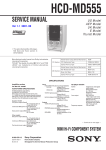
2.0 Application Block Diagram
The AU9412EEP is a single chip which integrates USB keyboard and hub functionality. The
upstream port is connected to the USB system. The downstream ports can be used for a mouse
and joystick.
APPLICATION BLOCK DIAGRAM
3
This Page Intentionally Left Blank
4
APPLICATION BLOCK DIAGRAM
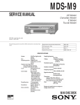
3.0 Pin Assignment
The AU9412EEP is a 48-pin dual inline package (DIP). The following figure shows the
signal names for each of the pins on the chip. The table on the following page describes each
of the pin signals.
PIN ASSIGNMENT
5
Table 3-1. Pin Descriptions
Pin #
6
Pin Name
I/O
Description
1
VCC3.3
O
2
USB_DP
I/O
USB D+ for upstream port. Need external 1.5KΩ pullup to 3.3V
3
USB_DM
I/O
USB D- for upstream port
4
USB1_DP
I/O
USB D+ for downstream port 1. Add 15KΩ pull-down
to ground
PIN ASSIGNMENT
3.3V output for upstream D+ pull-up; 4 mA
Table 3-1 (continued). Pin Descriptions
Pin #
Pin Name
I/O
5
USB1_DM
I/O
6
SCAN1_1
I
Matrix scan line; internal 3.3k pull-up
7
SCAN1_2
I
Matrix scan line; internal 3.3k pull-up
8
SCAN1_3
I
Matrix scan line; internal 3.3k pull-up
9
SCAN1_4
I
Matrix scan line; internal 3.3k pull-up
10
SCAN1_5
I
Matrix scan line; internal 3.3k pull-up
11
SCAN1_6
I
Matrix scan line; internal 3.3k pull-up
12
SCAN1_7/
EEP_DIN
I/O
Input: Matrix scan line; internal 3.3k pull-up.
Output: EEPROM data in; connect to EEPROM DIN
pin; 2 mA.
13
SCAN1_8/
EEP_CLK
I/O
Input: Matrix scan line; internal 3.3k pull-up.
Output: Clock for EEPROM; 2 mA.
14
SCR_LOCK
15
VDD
16
SCAN2_12
I/O
Matrix scan line; 16 mA, internal 33k pull-down
17
SCAN2_13
I/O
Matrix scan line; 16 mA, internal 33k pull-down
18
SCAN2_14
I/O
Matrix scan line; 16 mA, internal 33k pull-down
O
PWR
Description
USB D- for downstream port 1. Add 15KΩ pull-down
to ground
Scroll Lock LED. Active low; 8 mA
+5v power supply
PIN ASSIGNMENT
7
Table 3-1 (continued). Pin Descriptions
Pin #
Pin Name
19
SCAN2_15
I/O
Matrix scan line; 16 mA, internal 33k pull-down
20
SCAN2_16
I/O
Matrix scan line; 16 mA, internal 33k pull-down
21
SCAN2_17
I/O
Matrix scan line; 16 mA, internal 33k pull-down
22
SCAN2_18
I/O
Matrix scan line; 16 mA, internal 33k pull-down
23
EEP_CS
O
Chip select, external EEPROM; 2 mA
24
EEP_DOUT
I
EEPROM data out; connect to EEPROM DOUT pin;
2 mA
25
VDD_ANA
PWR
26
XTAL2
O
Crystal oscillator; XTAL-out
27
XTAL1
I
Crystal oscillator; XTAL-in
28
GND_ANA
29
SCAN2_3
I/O
Matrix scan line; 16mA, internal 33k pull-down
30
SCAN2_2
I/O
Matrix scan line; 16mA, internal 33k pull-down
31
SCAN2_1
I/O
Matrix scan line; 16mA, internal 33k pull-down
32
PW_SWITCH
33
GND
8
PIN ASSIGNMENT
I/O
PWR
O
PWR
Description
Analog power; connect to +5V
Analog Ground
Power switch control. Active low.
Ground; VSS pad
Table 3-1 (continued). Pin Descriptions
Pin #
Pin Name
I/O
I
Description
34
RESET#
Reset. Active low; Schmitt trigger input
35
VDD
PWR
+5v power; VDD pad
36
GND
PWR
Ground; VSS pad
37
SCAN2_4
I/O
Matrix scan line; 16mA, internal 33k pull-down
38
SCAN2_5
I/O
Matrix scan line; 16mA, internal 33k pull-down
39
SCAN2_6
I/O
Matrix scan line; 16mA, internal 33k pull-down
40
SCAN2_7
I/O
Matrix scan line; 16mA, internal 33k pull-down
41
SCAN2_8
I/O
Matrix scan line; 16mA, internal 33k pull-down
42
SCAN2_9
I/O
Matrix scan line; 16mA, internal 33k pull-down
43
SCAN2_10
I/O
Matrix scan line; 16mA, internal 33k pull-down
44
SCAN2_11
I/O
Matrix scan line; 16mA, internal 33k pull-down
45
USB2_DM
I/O
USB D- for downstream port 2. Add 15KΩ pull-down to
ground
46
USB2_DP
I/O
USB D+ for downstream port 2. Add 15KΩ pull-down
to ground
47
NUM_LOCK
O
Keyboard NUM_LOCK LED. Active low; 8 mA
48
CAP_LOCK
O
Keyboard CAP_LOCK LED. Active low; 8 mA
PIN ASSIGNMENT
9
This Page Intentionally Left Blank
10
PIN ASSIGNMENT
4.0 System Architecture and
Reference Design
4.1. AU9412EEP Block Diagram
SYSTEM ARCHITECTURE AND REFERENCE DESIGN
11
4.2. Sample Schematics
12
SYSTEM ARCHITECTURE AND REFERENCE DESIGN
4.3. Sample Key Matrix Layout Table
This table is the default key matrix. The AU9412EEP can support this matrix without an
external EEPROM.
Table 4-1. AU9412 Built-in Key Matrix
H1
H2
H3
H4
V1
Pause
V2
Q
Tab
V3
W
Caps
S
V4
E
F3
D
F4
A
ESC
H7
H8
Ctrl_R
H5
H6
Ctrl_L
F5
Z
~
1
X
F1
2
C
F2
3
V5
R
T
F
G
V
B
5
4
V6
U
Y
J
H
M
N
6
7
F6
+
8
APP
F8
9
“
/
-
Alt_L
Alt_R
V7
I
}
K
V8
O
F7
L
V9
P
{
:
V10
Scr_Lock
V11
<
>
0
Prt_Sc
BackSpace
|
F11
Enter
F12
F9
V12 Kpd_Home
Kpd_4
Kpd_1
Space
Num Lock
Arrow_Dn
Del
V13
Kpd_8
Kpd_5
Kpd_2
Kpd_0
Kpd_/
Arrow_Rt
Ins
V14
Kpd_9
Kpd_6
Kpd_3
Kpd_.
Kpd_*
Kpd_-
PgUp
PgDn
V15
Kpd_+
Kpd_Enter
Arrow_Up
Arrow_Lt
End
End
V16
Shift_L
V17
Win_L
V18
F10
Shift_R
Win_R
SYSTEM ARCHITECTURE AND REFERENCE DESIGN
13
This Page Intentionally Left Blank
14
SYSTEM ARCHITECTURE AND REFERENCE DESIGN
5.0 Electrical Characteristics
5.1. Maximum Ratings
Absolute Maximum Ratings
PARAMETER
Ambient Operating Temperatures
Storage Temperature
Supply Voltage (Vdd)
MIN
0• C
-40• C
-0.3V
VALUES
MAX
70• C
185• C
7.0V
5.2. Recommended Operating Conditions
The following table gives the recommended operating conditions for integrated circuits
developed with the pad libraries:
Symbol
VIL
VIH
VOL
VOH
ICC
Param.
Low level
input voltage
High level
input voltage
Low level
output voltage
High level
output voltage
Supply current
Min
-0.5V
Max
0.8V
2.0V
VDD+0.5V
0.4V
2.4V
20 mA
VDD
4.5V to
5.5V
4.5V to
5.5V
4.5V
4.5V
25 mA
Note
Guaranteed Input Low
Voltage
Guaranteed Input High
Voltage
IOL, 2 to 24 mA(TTL),
depending on Cell
IOH, 2 to 24mA(TTL)
depending on Cell
4.5V to
5.5V
ELECTRICAL CHARACTERISTICS
15
5.3. Crystal Oscillator Circuit Setup for Characterization
The following setup was used to measure the open loop voltage gain for crystal oscillator
circuits. The feedback resistor serves to bias the circuit at its quiescent operating point and
the AC coupling capacitor, Cs, is much larger than C1 and C2.
5.4. USB Transceiver Characteristics
RECOMMENDED OPERATING CONDITIONS
SYMBOL
PARAMETER
CONDITIONS
VCC
VI
VI/O
VO
T
DC supply voltage
DC input voltage range
DC input range for I/Os
DC output voltage range
Operating ambient temperature
range in free air
16
ELECTRICAL CHARACTERISTICS
AMB
See DC and AC
characteristics for
individual device
LIMITS
MIN
3.0
0
0
0
0
UNIT
MAX
3.5
5.5
VCC
VCC
70
V
V
V
V
•
C
ABSOLUTE MAXIMUM RATINGS 1, 2
In accordance with the Absoute Maximum Rating System, Voltages are referenced to GND (Ground=0v)
SYMBOL
PARAMETER
CONDITIONS
V
V
V
V/
DC supply voltage
DC input diode current
DC input voltage
DC input voltage range for I/Os
Vi<0
Note 3
V
V
DC output diode current
DC output voltage
Vo> Vcc or Vo<0
Note 3
DC output source sink current
for VP/VM and RCV pins
DC output source or sink
current for D+/D- pins
DC Vcc or GND current
Storage temperature range
Power dissipation per package
Vo=0 to Vcc
LIMITS
MIN
MAX
-0.5
+6.5
-50
-0.5
+5.5
-0.5
Vcc
+0.5
+/-50
-0.5
Vcc
+0.5
+/-15
Vo= 0 to Vcc
+/-50
mA
+/-100
+/-150
mA
•
C
mW
CC
IK
I
IO
OK
O
V
O
V
O
I ,I
T
P
GND
STG
TOT
GND
-60
UNIT
V
mA
V
V
mA
V
mA
NOTES:
1. Stresses beyond those listed may cause permanent damage to the device. These are stress ratings
only and functional operation of the device at these or any other conditions beyond those indicted
under "Recommended Operating Conditions" is not implied. Exposure to absolute maximum rated
conditions for extended periods may affect device reliability.
2. The performance capability of a high performance integrated circuit in conjunction with its thermal
environment can create junction temperatures which are detrimental to reliability. The maximum
junction temperature of this integrated circuit should not exceed 150•C.
3. The input and output voltage ratings may be exceeded if the input and output clamp current ratings
are observed.
ELECTRICAL CHARACTERISTICS
17
DC ELECTRICAL CHARACTERISTICS
Over recommended operating conditions. Voltages are referenced to GND (Ground=0V).
Vcc=3.0V to 3.6V
Vcc=3.0V to 3.6V
Vcc=3.0V to 3.6V
Note 2
LIMITS
-40•C to +86•C
MIN
TYP MAX
5.2
4.3
50.4
15
20
0.5
11
28
34
43
V
V
V
ohm
Note 2
28
35
ohm
Vcc=3.0V Io=6mA
Vcc=3.0V Io=4mA
Vcc=3.0V Io=100µA
Vcc=3.0V Io=6mA
Vcc=3.0V Io=4mA
Vcc=3.0V Io=100µA
Vcc=3.6V VI=Vcc or GND
Io=0
Vcc=3.6V VI=Vcc or GND
Io=0
Vcc=3.3V
2.2
2.4
2.8
2.7
SYMBOL
PARAMETER
TEST CONDITIONS
VHYS
VIH
VIL
RoH
VOH
Hysteresis on inputs
HIGH level input
LOW level input
Output impedance (HIGH
state)
Output impedance (LOW
state)
HIGH level output
VOL
LOW level output
IQ
Quiecient supply current
Isup
Supply current in suspend
IFS
Active supply current (Full
Speed)
Active supply current (Low
Speed)
Imput leakage current
RoL
ILS
ILeak
IOFF
3-state output OFF-state
current
0.3
330
9
Vcc=3.3V
2
Vcc=3.6V VI=5.5V or
GND, not for I/O Pins
VI=VIN or VII, Vo=Vcc or
GND
+/0.1
43
UNIT
V
0.7
0.4
0.2
600
V
70
µA
14
mA
µA
mA
+/0.5
+/-1-
µA
µA
NOTES:
1. All typical values are at Vcc=3.3V and Tamb=25•C.
2. This value includes an external resistor of 24 ohm +/-1%. See "Load D+ and D-" diagram for testing
details.
3. All signals except D+ and D-.
18
ELECTRICAL CHARACTERISTICS
AC ELECTRICAL CHARACTERISTICS
GND=0V, Is = IS=3.0 C=50pf, RL=500ohms
SYMBOL
PARAMETER
tpLH
tpHL
trise
tfall
tRFM
VMO/VPO to D+/DFull Speed
Rise and Fall Times
Full Speed
Rise and Fall Time
Matching
Full Speed
VMO/VPO to D+/DLow Speed
Rise and Fall Times
Low Speed
Rise and Fall Time
Matching
Low Speed
D+/D- to RCV
1
D+/D- to VP/VM
1
OE# to D+/D- RL =
500ohm
4
Setup for SPEED
Crossover point
5
3
tpLH
tpHL
trise
tfall
tRFM
tpLH
tpHL
tpLH
tpHL
tpHZ
tpZH
tpLZ
tpZL
Vcp
WAVFORM
1
2
LIMITS
-40•C to +86•C
-40•C to +86•C
MIN
TYP MAX MIN
MAX
0
12
0
14
0
12
0
14
4
9
20
4
20
4
9
20
4
20
90
110
90
110
1
2
120
120
75
75
70
3
9
9
4
4
0
1.3
300
300
300
200
130
75
75
70
16
16
8
8
12
12
10
10
2.0
1.3
UNIT
ns
ns
%
300
300
300
200
130
ns
16
16
8
8
12
12
10
10
ns
2.0
ns
%
ns
ns
ns
V
NOTE:
1. The crossover point is in the range of 1.3V to 2.5V for the low speed mode with a 5Cpf capacitance.
ELECTRICAL CHARACTERISTICS
19
20
ELECTRICAL CHARACTERISTICS
5.5. ESD Test Results
Test Description: ESD Testing was performed on a Zapmaster system using the HumanBody-Model (HBM) and Machine-Model (MM), according to MIL-STD 883 and EIAJ IC121 respectively.
• Human-Body-Model stresses devices by sudden application of a high voltage supplied by
a 100pF capacitor through 1.5k-ohm resistance.
• Machine-Model stresses devices by sudden application of a high voltage supplied by a
200pF capacitor through very low (0 ohm) resistance.
Test Circuit & Condition
- Zap Interval: 1 second
- Number of Zaps: 3 positive and 3 negative at room temperature
- Criteria: I-V Curve Tracing
ESD Data
Model
HBM
MM
Mode
Vdd, Vss, I/C
Vdd, Vss, I/C
S/S
15
15
Target
2000V
200V
Results
PASS
PASS
ELECTRICAL CHARACTERISTICS
21
5.6. Latch-Up Test Results
Test Description: Latch-Up testing was performed at room ambient using an IMCS-4600
system which applies a stepped voltage to one pin per device with all other pins open except
Vdd and Vss which were biased to 5Volts and ground respectively.
Testing was started at 5.0V (Positive) or 0V (Negative), and the DUT was biased for 0.5
seconds.
If neither the PUT current supply nor the device current supply reached the predefined limit
(DUT=00mA, Icc=100mA), then the voltage was increased by 0.1Volts and the pin was tested
again.
This procedure was recommended by the JEDEC JC-40.2 CMOS Logic standardization
committee.
Notes:
1. DUT: The device under test.
2. PUT: The pin under test.
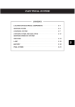
Test Circuit: Positive Input/Output Overvoltage/Overcurrent
22
ELECTRICAL CHARACTERISTICS
Test Circuit: Negative Input/Output Overvoltage/Overcurrent
Supply Overvoltage Test
Latch-Up Data
Mode
+
Voltage
+
Current
Vdd - Vxx
Voltage (V)/Current (mA)
11.0
11.0
200
200
9.0
S/S
5
5
5
5
5
Results
Pass
Pass
Pass
Pass
Pass
ELECTRICAL CHARACTERISTICS
23
This Page Intentionally Left Blank
24
ELECTRICAL CHARACTERISTICS
6.0 Mechanical Information
Following diagram shows the dimensions of Alcor AU9412EEP 48-DIP package.
Measurements are in millimeters; measurements in parenthesis are in inches.
MECHANICAL INFORMATION
25


![Technologie des circuit intégrés (composants) [Format PDF]](http://vs1.manualzilla.com/store/data/006460848_1-f135636d429cc786ac12f54c88c1d7c9-150x150.png)