1
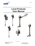
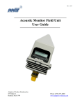
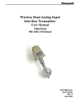
Installation and User’s Guide
Wireless Resistance Transceiver
(WRT)
M357 Rev E
September 23, 2009
JOWA USA, Inc.
59 Porter Road
Littleton, MA 01460-1431
Phone: 978-486-9800
Fax: 978-486-0170
Jowa USA Resistance Transceiver
Installation and User’s Guide
Important Information to User
•
Changes or modifications not expressly approved by the manufacturer may void the user’s
authority to operate the equipment.
•
This device complies with Part 15 of the FCC Rules. Operation is subject to the following two
conditions: 1) this device may not cause harmful interference, and 2) this device must accept any
interference received, including interference that may cause undesired operation.
•
This device is for mobile and fixed use only (not portable or body-worn). A separation distance of
20cm must be maintained at all times between the antenna and the body of the user and bodies
of nearby persons.
•
This device is protected by US Patent 6,338,283 and other Pending Patents
FCC Certification
•
This product is a frequency hopping RF transceiver module for the 900MHz ISM band, designed
to meet FCC 15.247, and is used in industrial control and monitoring applications.
•
The antenna is factory installed and MUST NOT be removed or modified by user.
Table of Contents
INTRODUCTION
6
UNPACKING
6
A QUICK START GUIDE
7
CONFIGURING THE FIELD UNIT FOR RF COMMUNICATIONS
8
FIELD UNIT DISPLAYED MESSAGES
RF CHANNEL SETUP
BAUD RATE SETUP
FIELD UNIT IDENTIFICATION SETUP
8
11
12
13
SETTING THE FIELD UNIT USER PASSWORD
14
SETTING THE FIELD UNIT TAG NAME
15
MECHANICAL INSTALLATION
16
FIELD UNIT POSITIONING
A SIMPLE RF PLACEMENT TEST
16
18
ELECTRICAL INSTALLATION
19
M357 Rev. E
Page 3
Jowa USA Resistance Transceiver
Installation and User’s Guide
CONFIGURING FIELD UNIT SAMPLE SETTINGS
20
SETTING THE NORMAL TRANSMIT RATE
SETTING THE NORMAL SAMPLING RATE
SETTING THE ABNORMAL TRANSMIT RATE
SETTING THE ABNORMAL SAMPLING RATE
SETTING THE NORMAL UPPER AND LOWER VALUES
SETTING THE SMART RATE THRESHOLD
20
21
25
26
28
31
SELECTING UNITS OF MEASURE
32
SELECTING THE SENSOR OUTPUT LIMITS
33
SETTING A MEASUREMENT OFFSET
36
TRIMMING THE MEASUREMENT
37
MAINTAINING THE FIELD UNIT
38
CHANGING THE BATTERY
38
APPENDIX A - NAVIGATING THE USER MENUS
41
APPENDIX B - FIELD UNIT PARAMETER DEFAULTS AND LIMITS
42
APPENDIX C - FIELD UNIT MENU MAP
43
APPENDIX D - FIELD UNIT DISPLAYED MESSAGE DEFINITIONS
46
M357 Rev. E
Page 4
Jowa USA Resistance Transceiver
Installation and User’s Guide
Table of Figures
Figure 1:
Field Unit Power-Up and Operations LCD Sequence................................................8
Figure 2:
The Read Only Sequence .........................................................................................9
Figure 3:
Overall Configuration Menu Map .............................................................................10
Figure 4:
Menu Map to RF Channel Setting............................................................................11
Figure 5:
Menu Map to Baud Rate Setting..............................................................................12
Figure 6:
Menu Map to RF ID Setting .....................................................................................13
Figure 7:
Menu Map to Password Setting ...............................................................................14
Figure 8:
Menu Map to Set Tag Name....................................................................................15
Figure 9:
Examples of Incorrect Field Unit Positioning ...........................................................17
Figure 10: Resistance-tape / Field Unit Wiring..........................................................................18
Figure 11: Menu Map to Normal Transmit Rate........................................................................20
Figure 12: Battery Life Charts ...................................................................................................22
Figure 13: Incorrect Normal Sample Rate Setting ....................................................................23
Figure 14: Correct Normal Sample Rate Setting.......................................................................23
Figure 15: Menu Map to Normal Sample Rate Setting .............................................................24
Figure 16: Example of Abnormal Transmit Rate Setting...........................................................25
Figure 17: Menu Map to Abnormal Transmit Rate Setting........................................................26
Figure 18: Example of Abnormal Sampling Rate Setting..........................................................27
Figure 19: Menu Map to the Abnormal Sampling Rate Setting.................................................27
Figure 20: Normal Upper and Lower Value Example................................................................28
Figure 21: Menu Map to Normal Upper and Lower Value Settings...........................................29
Figure 22: Example of Condition "Chatter" without Time Deadband ........................................30
Figure 23: Example of Condition "Chatter" Elimination Due to 20 sec Time Deadband ...........30
Figure 24: Menu Map to Units Setting.......................................................................................32
Figure 25: Menu Map to Sensor Setting ...................................................................................35
Figure 26: Menu Map to Offset Setting .....................................................................................36
Figure 27: Menu Map to Trim Setting........................................................................................37
M357 Rev. E
Page 5
Jowa USA Resistance Transceiver
Installation and User’s Guide
Introduction
The Wireless Resistance Transceiver is a reliable Radio Frequency (RF)
transceiver and when coupled with a resistance-tape level sensor it can be used
to monitor a variety of tanks or processes in hazardous and hard-to-reach areas.
The time and expense of running wires often makes it difficult to measure
parameters that have an economic impact on your plant operation, but the
Resistance Transceiver allows you to quickly and accurately monitor those levels
at fraction of the cost, which gives you bigger and faster returns on your
instrumentation investments.
The Transceivers or Field Units communicate in a secure, digital protocol over a
band of frequencies from 902MHz to 928MHz. This data communication
technique has been the backbone of the military’s secure communications
protocols for many years. These devices require no wires, permits or licenses,
and are easily setup and installed right out of the box.
You can use this device for long term monitoring in remote locations, for shortterm data gathering on process conditions, or to quickly test the economic
viability of a new installation.
The purpose of this Guide is to help you install and maintain your Wireless
Resistance Transceiver. BEFORE setting up and installing the Field Unit please
setup and configure the Base Radio. (See the Wireless Base Radio Guide, M356,
for more details).
Unpacking
Remove the Packing List and check off the actual equipment received. If you
have any questions on your shipment, please call the factory. Upon receipt of
shipment, inspect the container for any signs of damage in transit. Especially
take note of any evidence of rough handling. Report any apparent damage
immediately to the shipping agent.
Please note that sometimes units are assembled with accessories when shipped.
Inspect the shipment carefully if you think that something is missing. This is rare,
as we take considerable care to pack units for shipment, but it does sometimes
happen. Please give us a call and we may be able to resolve this matter quickly
over the phone.
Please note that the carrier will not honor any claims for damage unless
all shipping materials are saved for their examination. If damage is
found during examining and removal of the contents, save the packing
material and the carton.
M357 Rev. E
Page 6
Jowa USA Resistance Transceiver
Installation and User’s Guide
A Quick Start Guide
To get the Field Unit up and running quickly, follow the steps below:
NOTE: If you are unsure how to perform a task please read the
appropriate user manual section.
1.
Place the Field Unit in the desired location of operation
2.
Turn on the Field Unit by pressing the two buttons for 1 second
3.
The Field Unit Settings need to be configured as follows:
• Set RF CHAN to match the Base Radio RF CHAN
• Set BAUD RT to match the Base Radio BAUD RT
• Set RF ID to next consecutive available ID (not 0) starting at 001
The Field Unit should now be configured for use. The Field Unit will show the
messages in the figure below (Note that the POWER-UP Sequence is only
shown when the device is first turned on:
If you are not receiving an “RF OK” message on the Field Unit check the
following:
•
•
•
•
•
M357 Rev. E
Is the Field Unit set to the above listed configurations?
Is the Base Radio on?
Are the Field Unit and Base Radio set to the matching configurations?
(See Base Radio Quick Start Guide)
Are the Base Radio and Field Units unable to communicate due to
obstructions or distance? (See Field Unit Guide: Field Unit Placement
section)
Did you perform the Simple RF Placement Test? (See Field Unit Guide: A
Simple RF Placement Test section)
Page 7
Jowa USA Resistance Transceiver
Installation and User’s Guide
Configuring the Field Unit for RF Communications
In order for the Field Unit and the Base Radio to communicate they must be on
the same RF Channel, and must be transmitting at the same Baud Rate. While
all Field Units and Base Radios are set to default configurations at the factory, if
any configuration differences are present the Field Unit will not be able to
communicate to the Base Radio.
NOTE: If you are unfamiliar on how to navigate the Field Unit menus,
please refer to Appendices A-C. Also, BEFORE setting up and installing
the Field Unit please setup and configure the Base Radio. (See the
Wireless Base Radio Guide, M356, for more details).
Field Unit Displayed Messages
To turn the Field Unit on, press the NEXT and ENTER buttons located on the
front of the Field Unit just below the Liquid Crystal Display (LCD) screen for 1
second. Turn on the Base Radio as well, if you have not already done so. The
LCD will then display a Power-Up Sequence and then go into an Operations
Sequence. These Sequences are seen below in Figure 1:
Figure 1: Field Unit Power-Up and Operations LCD Sequence
NOTE: During configuration and installation, keep Field Units at least one
foot apart and away from the Base Radio to ensure good communications.
M357 Rev. E
Page 8
Jowa USA Resistance Transceiver
Installation and User’s Guide
The Read-Only Sequence
Once the Field Unit is in the Operations Sequence, a user may access the
READ-ONLY Sequence without a password by simply pressing the ENTER
button at any time. The Read-Only Sequence, as shown in Figure 2, displays
extra information about the current settings of the Field Unit that are not seen
during the Operations Sequence, but does not allow any changes to be made to
these settings.
Figure 2: The Read Only Sequence
M357 Rev. E
Page 9
Jowa USA Resistance Transceiver
Installation and User’s Guide
Overall Configuration Menu Map
A complete Field Unit Menu Map is shown in Appendix C. Below is an overall
view of the configuration menu to aid the user in setting up the Field Unit for
proper operation.
Figure 3: Overall Configuration Menu Map
NOTE: The user must enter a four digit password to enter the CONFIG and
DIAGNSE. The FACTORY menu is for factory use only. The factory default user
password is 0000. For more information on the password see the Setting the
Password section.
M357 Rev. E
Page 10
Jowa USA Resistance Transceiver
Installation and User’s Guide
RF Channel Setup
All Field Units and Base Radios can be set to one of 16 different communication
channels. The only Field Units recognized by a particular Base Radio are the
units that share the same RF Channel as that Base Radio. This allows the user
decide which Field Units communicate with each Base Radio.
Each Field Unit comes from the factory set to the RF OFF channel. This means
the Field Unit will not communicate to any Base Radio. To set the Field Unit for
communication first determine the channel that you wish to use. Then confirm
Base Radio is set to this same channel.
Follow the Field Unit Menu Map in Figure 4 to configure the RF Channel setting.
The factory default is RF OFF.
Figure 4: Menu Map to RF Channel Setting
Increment the channel until it matches the channel you noted from the Base
Radio. Then save and exit the menus and return to the Operations Sequence.
M357 Rev. E
Page 11
Jowa USA Resistance Transceiver
Installation and User’s Guide
Baud Rate Setup
The Baud Rate refers to the speed at which the Base Radio and Field Units
communicate. There are three selectable settings:
4.8K
19.2K
76.8K
- Baud rate of 4.8 Kbaud (Update every 20 seconds)
- Range of 3000ft
- Baud rate of 19.2 Kbaud (Update every 5 seconds)
- Range of 2000ft to 2500ft
- Baud rate of 76.8 Kbaud (Update every 1 second)
- Range of 500ft to 750ft
A faster baud rate will allow you to transmit more information in a certain period of
time, but it will also limit your range. If you need more distance out of your Field
Unit or are encountering difficulties by frequently losing communications, then
select a slower baud rate.
First determine the Baud Rate the Base Radio is transmitting at. Then follow the
Field Unit menu map shown in Figure 5 to configure the Baud Rate. The factory
default is the 19.2K Baud Rate.
Figure 5: Menu Map to Baud Rate Setting
Once you have selected the Baud Rate you wish to use, save and exit the menus
and return to the Operations Sequence.
M357 Rev. E
Page 12
Jowa USA Resistance Transceiver
Installation and User’s Guide
Field Unit Identification Setup
Each Field Unit is identified by the Base Radio and software according to the
Identification (ID) given to that particular unit. Two Field Units can NOT have the
same ID and be on the same RF Channel (if you do not know the RF Channel
see the RF Channel Setup section). If the Field Unit is in the Operations
Sequence, pressing the ENTER button displays the Read-Only Sequence on the
LCD which displays the ID of that unit like this: ID 3.
All Field Units in your system are set to a default ID number upon shipment. For
example, if you have ordered a Base Radio and three Field Units, the Field Units
will be configured to ID’s 0, 0 and 0. You must set these units to three different
consecutive numbers, starting with 1, in order for the communications to work
properly. The Field Units in this example would be set to RF ID’s 1, 2 and 3.
First determine the ID’s you’d like to give each unit. Then follow the menu map
shown in Figure 6 to configure the RF ID. The factory default is RF ID 0, which
disables the RF communications of the unit.
Figure 6: Menu Map to RF ID Setting
Once you have selected the RF ID you wish to use for this particular Field Unit,
save and exit the menus and return to the Operations Sequence.
The Field Unit should now be successfully configured to the Base Radio. To
check this, press ENTER while the Field Unit is in the Operations Sequence for
the Read-Only Sequence to be displayed. You may see an RF SYNC message
displayed on the Field Unit LCD. This means that the Field Unit and Base Radio
are attempting to synchronize communications. If this is successful the RF Status
will display an RF OK message. If this is unsuccessful the RF Status will display a
NO RF message.
Also notice the two small arrows on either side of the LCD; if they are fluctuating
up and down, that indicates the Field Unit and Base Radio are successfully
communicating. If only one or none of the arrows are moving then RF
communication is unsuccessful.
M357 Rev. E
Page 13
Jowa USA Resistance Transceiver
Installation and User’s Guide
Setting the Field Unit User Password
Each Field Unit has a password that will lock out undesired users from making
changes to the Field Unit. Any user may still view some of the Field Unit settings
by pressing the ENTER key during the Operations Sequence and viewing the
Read Only Sequence.
The password is a four digit password much like a pin number from a bank. The
factory default is 0000. Please select a different password if you wish. Follow the
Field Unit Menu Map below to change the password.
Figure 7: Menu Map to Password Setting
If you forget your password you must call the factory for a password reset
command.
M357 Rev. E
Page 14
Jowa USA Resistance Transceiver
Installation and User’s Guide
Setting the Field Unit Tag Name*
Each Field Unit also has a user settable Field Unit Tag Name. This tag name is
displayed upon Field Unit power up, and when the Read Only Sequence is
selected. The Tag Name is a 21 character name that is displayed in three
separate 7 character flashes on the Field Unit LCD.
The user may choose from A-Z, 0-9, a dash (“-“), and an underscore (“_”). The
underscore has a special meaning to the software inside the Field Unit. For
example, if you have a Tag Name that is only 5 characters long, then you do not
want to wait for the rest of the 16 characters to be displayed on the LCD. So if
your Tag Name was “TANK1”, you would want to enter the Tag Name like this:
“TANK1 _ _ _ _ _ _ _ _ _ _ _ _ _ _ _”.
The software then recognizes this and only displays “TANK1”, and negates the 2
extra 7 character flashes. (“TANK_ _ 1_ _ _ _ _ _ _ _ _ _ _ _ _ _” becomes
“TANK 1” and so on).
Select the Tag Name you’d like give the Field Unit and follow the Field Unit Menu
Map below:
Figure 8: Menu Map to Set Tag Name
*
Indicates that Menu is Disabled if Wireless Instrumentation Manager is used. (See Appendix A)
M357 Rev. E
Page 15
Jowa USA Resistance Transceiver
Installation and User’s Guide
Mechanical Installation
The Wireless Resistance Transceiver is a rugged device, but it will give much
better service if installed with careful consideration as noted in this manual. They
may be utilized for just about any installation so long as care is exercised to
prevent exposing the sensing elements to excess stress or temperature.
Installation practices have a lot to do with these service parameters and the life
that you can expect from your Wireless Resistance Transceiver. The main
considerations for installation are covered below.
Give careful consideration to the environment where you will be installing your
instrument. Avoid installations that expose the device to excess temperature,
high vibration, considerable shock, or exposure to dripping condensate or
corrosive materials. Also avoid installing the device in an unserviceable location.
Most often these problems can be avoided with some thought at the time of
installation. The practices noted below are generally recommended, but they can
only act as a guideline and cannot cover all possible variations. The final
installation must be made at the discretion and approval of the user. You must
be the judge of the actual installation.
WARNING:
DURING INSTALLATION DO NOT APPLY FORCE TO THE
INSTRUMENT HOUSING. USE A PROPER WRENCH ON THE
HEXAGONAL FLATS PROVIDED ONLY. FAILURE TO USE
CORRECT INSTALLATION PROCEDURE CAN CAUSE DAMAGE TO
THE FIELD UNIT.
Field Unit Positioning
Correct positioning of the Field Unit will ensure the best performance of the
device. When planning the positioning of the Field Units there are a few
parameters to pay attention to.
1.
Ideally the Field Unit should be mounted in the hole
provided in the sensor housing. Tighten the Field
Unit to the box with the provided locknut. See the
adjacent figure. In any case the bottom of the Field
Unit should NOT point directly at the Base Radio.
2.
All Field Units should maintain an approximate
spacing of at least one foot.
3.
The line of sight range between a Field Unit and
Base Radio is 2000 feet at the 19.2K baud rate
setting. Note that the amount of RF Noise present,
obstructions, and the material of construction of the
objects, reduces this range.
M357 Rev. E
Page 16
Jowa USA Resistance Transceiver
4.
Installation and User’s Guide
Only place the Field Unit in ambient operating temperatures of -40°F to
185°F (-40°C to 85°C).
Figure 9, shown below, gives examples of incorrect setups according to the
previously mentioned parameters.
Figure 9: Examples of Incorrect Field Unit Positioning
Because there are so many setup possibilities we cannot cover them all. A
correct setup would make sure that the above warnings are heeded, and that the
Field Unit and Base Radio are capable of communication. The RF Placement
Test section will help you to determine if you have a selected the correct
installation points and orientations for your application.
M357 Rev. E
Page 17
Jowa USA Resistance Transceiver
Installation and User’s Guide
A Simple RF Placement Test
Remember, proper placement of the Field Unit will optimize your RF
communication range and capabilities. Perhaps the best test to perform before
mechanically mounting the unit is a quick hand held test.
To perform this test you should have a good idea of where the Base Radio will be
placed (for more information see the Base Radio Installation and User’s Guide).
Put the Base Radio in this area and power it up. Now, make sure that the Base
Radio and Field Unit are on the same RF Channel, and Baud Rate (See the
Configuring to the Base Radio Section). You may also have to increment the
number of Field Units that are being communicated with on the Base Radio (See
the Base Radio User’s Guide).
Once both the Base Radio and Field Unit are configured to one another, make
sure communications are established by looking on the Field Unit LCD for an ‘RF
OK’ message in the Read-Only Sequence (see Read-Only Sequence section).
Now take the Field Unit to the sensor you wish to monitor. Hold the Field Unit
over the mounting hole. Look at the LCD; in both the right and left most regions
you will notice a small arrow. This arrow indicates the sending and receiving of
messages between the Base Radio and Field Unit. If both arrows are moving up
and down, and you do not see a NO RF message, then the position you have
selected will be suitable place for mounting the device.
If only one or neither of the arrows is moving, and you see a NO RF message,
then you do not have RF communication with the Base Radio. If your application
allows, move to a different position and check again for communications. If your
application only allows you to mount at this particular point, you may want to try a
slower baud rate setting.
Note: While slowing the baud rate increases communication distance, it
also requires more time to complete a communications cycle. This may
not be suitable for your application.
One final solution is to reposition the Base Radio, however, this may affect
communications with previously installed Field Units; and if so, may require the
use of a second Base Radio for your application. To select a better spot for the
Base Radio, see the Positioning the Base Radio section of the Base Radio
User’s Guide).
M357 Rev. E
Page 18
Jowa USA Resistance Transceiver
Installation and User’s Guide
Electrical Installation
When the Field Unit is mounted to the cover of the sensor housing, simply plug
the sensor connector to the mating Field Unit connector.
Mounting Instructions
1. Remove Housing Cover from Housing
2. Remove Locknut from Field Unit
3. Make sure Seal Washer will have
rubber side against Housing Cover
4. Insert Plug from Field Unit through hole
in Housing Cover.
5. Push Locknut over Field Unit Plug and
up wire. Thread Locknut onto Field
Unit hand tight.
6. Orient Transceiver display to desired
position.
7. While holding hex on Field Unit, tighten
Locknut until Seal Washer is flat
against housing Cover.
8. Plug Field Unit into sensor and install
Housing Cover onto Housing.
Figure 10: Resistance-tape / Field Unit Wiring
M357 Rev. E
Page 19
Jowa USA Resistance Transceiver
Installation and User’s Guide
Configuring Field Unit Sample Settings
The Wireless Resistance Transceiver is very versatile with many programmable
features and can be used in numerous different applications. Because no two
applications are the same, some calibration is required for each unit. This section
will walk you through the initial calibration of these Sampling Settings.
Setting the Normal Transmit Rate*
The Field Unit is in a “sleep” mode to save power during the operations
sequence. This mode turns off most of the electronics on the unit, with the
exception of the LCD, in order to preserve battery life. The Field Unit will then
‘wake up’ for every Normal Sampling Rate and take the necessary
measurement. The Field Unit will then transmit these readings to the Base Radio
every so many seconds, depending on the Normal Transmit Rate.
The first item to note is that the maximum speed of the Normal Transmit Rate is
dependent on the Baud Rate setting you selected earlier (see Baud Rate Setup).
The Transmit Rates cannot update faster than their communication speed allows.
Thus, if you selected the 19.2K Baud Rate setting your maximum Transmit Rates
will be the 5 Second setting. The Field Unit automatically determines these
settings and adjusts the menu options accordingly. A complete table of these
parameters is shown in Table 1 on page 21.
In order to properly set the Normal Transmit Rate, you must first determine how
often you need updates from the Field Unit when the device being monitored is
operating normally. You have a selectable range of 1-5, 10, 15, 20, 40 seconds
and 1 minute.
Then, follow the menu map shown in Figure 11 to configure the Normal Transmit
Rate. The factory default is 10 Seconds.
Figure 11: Menu Map to Normal Transmit Rate
*
Indicates that Menu is Disabled if Wireless Instrumentation Manager is used. (See Appendix A)
M357 Rev. E
Page 20
Jowa USA Resistance Transceiver
Installation and User’s Guide
Setting the Normal Sampling Rate*
As mentioned before, the Field Unit is in a “sleep” mode to save power during the
operations sequence. This mode turns off most of the electronics on the unit, with
the exception of the LCD, in order to preserve battery life. The Field Unit will then
‘wake up’ for every Normal Sampling Rate and take the necessary level
readings.
The first item to note is that the minimum speed of the Normal Sampling Rate is
dependent on the Normal Transmit Rate setting you selected earlier (see Setting
the Normal Transmit Rate). The Sampling Rates cannot update slower than the
speed at which the Field Unit is required to transmit updates. Thus, if you
selected the Normal Transmit Rate setting to be 10 Seconds the Normal
Sampling Rate must be set to 10 Seconds or faster. A complete table of these
parameters is shown below:
Baud Rate
(communication range)
(speed of updates)
Normal and Abnormal
Transmit Rates
Normal and Abnormal
Sampling Rates
76.8K
500-750 feet
1 Second
1 Second or
Greater
Equal to Transmit
Rate or Less
19.2K
2000-2500 feet
5 Seconds
5 Seconds or
Greater
Equal to Transmit
Rate or Less
4.8K
3000 feet
20 Seconds
20 Seconds or
Greater
Equal to Transmit
Rate or Less
Table 1: Rate Limits and Dependencies
In order to properly set the Normal Sampling Rate, first determine how often
updates are needed from the Field Unit when the device being monitored is
operating normally. You have a selectable range of 1-30 seconds. Note, however,
the more frequent the Field Unit wakes up to check the monitored device, the
faster you will use up the battery life of the Field Unit. This is indicated on the
three charts in Figure 12 shown below:
Battery Life Calculator (76,800 FAST) Sensor (various sensor sample rates)
12
Battery Life (yrs)
10
8
twice second
once second
6
every 5 seconds
4
2
0
1
5
10
20
RF Update Period (seconds)
*
Indicates that Menu is Disabled if Wireless Instrumentation Manager is used. (See Appendix A)
M357 Rev. E
Page 21
Jowa USA Resistance Transceiver
Installation and User’s Guide
Battery Life Calculator (19,200 NORMAL) Sensor (various sensor sample rates)
12
Battery Life (yrs)
10
8
twice second
once second
6
every 5 seconds
4
2
0
1
5
10
20
RF Update Period (seconds)
Battery Life Calculator (4,800 SLOW) Sensor (various sensor sample rates)
12
Battery Life (yrs)
10
8
twice second
6
once second
every 5 seconds
4
2
0
20
40
60
RF Update Period (seconds)
Figure 12: Battery Life Charts
Figure 13, shown below, is an example of what happens when the Normal
Sampling Rate is too large for the device being sampled. Notice how the rise in
the level falls between two normal samples, and thus goes completely
undetected.
M357 Rev. E
Page 22
Jowa USA Resistance Transceiver
Installation and User’s Guide
Level
(inches)
Figure 13: Incorrect Normal Sample Rate Setting
Figure 14, shown below, is an example of what happens when the normal
sampling rate is correctly set for the device that is being monitored. Notice how
this setting is able to sample the rise in the level.
Level
(inches)
Figure 14: Correct Normal Sample Rate Setting
Once you have decided the proper time for the Normal Sampling Rate follow the
Field Unit menu map shown in Figure 15. The factory default is 1 second.
M357 Rev. E
Page 23
Jowa USA Resistance Transceiver
Installation and User’s Guide
Figure 15: Menu Map to Normal Sample Rate Setting
Note: The Field Unit adjusts the menu options according to the previously
set Baud Rate and Transmit Rate settings.
M357 Rev. E
Page 24
Jowa USA Resistance Transceiver
Installation and User’s Guide
Setting the Abnormal Transmit Rate*
The Abnormal Transmit Rate is identical to the Normal Transmit Rate with one
exception. The Abnormal Transmit Rate only applies while the Field Unit is in an
Abnormal condition (see Setting Normal Upper and Lower Values). This allows
you to increase or decrease the frequency of information you receive depending
on the operating conditions of the device being monitored.
Note: If you do not need more or less frequent samples and updates from
a Field Unit for a given application, then there is no need to complete this
section. Simply set the Normal Transmit and Sample Rates to the desired
speeds, and make sure that the Normal Upper and Lower Values are
configured to Disabled.
In order to properly set the Abnormal Transmit Rate, you must first determine
how often the Field Unit needs to update you about the device being monitored
while in an Abnormal condition. You have a selectable range of 1-10, 15, 20, 40
seconds and 1, 5, 10, 30, 60 minutes. Figure 16 is an example of how the device
switches sampling methods from Normal Transmit Rates to Abnormal Sampling
Rates.
Level
(inches)
Figure 16: Example of Abnormal Transmit Rate Setting
The Field Unit only recognizes the Abnormal condition when a Normal Sample is
above the Normal Upper Value. Once the Field Unit is in the Abnormal condition,
it has changed from the Normal Transmit Rate of 1 Min, to the Abnormal Transmit
Rate of 10 seconds. This continues until the Abnormal condition is over, and then
the Field Unit returns to the Normal Transmit Rate.
Once you have decided the proper time for the Abnormal Transmit Rate follow
the Field Unit menu map shown in Figure 17.
*
Indicates that Menu is Disabled if Wireless Instrumentation Manager is used. (See Appendix A)
M357 Rev. E
Page 25
Jowa USA Resistance Transceiver
Installation and User’s Guide
Figure 17: Menu Map to Abnormal Transmit Rate Setting
Note: The Field Unit adjusts the menu options according to the previously
set Baud Rate settings.
Setting the Abnormal Sampling Rate*
The Abnormal Sampling Rate is identical to the Normal Sampling Rate with one
exception. The Abnormal Sampling Rate only applies while the Field Unit is in an
Abnormal condition (see Setting Normal Upper and Lower Values). This allows
you to increase or decrease the frequency the Field Unit checks the monitored
equipment depending on the operating conditions.
Note: If you do not need more or less frequent samples and updates from
a Field Unit for a given application, then there is no need to complete this
section. Simply set the Normal Transmit and Sample Rates to the desired
speeds, and make sure that the Normal Upper and Lower Values are
configured to Disabled.
In order to properly set the Abnormal Sampling Rate, you must first determine
how often the Field Unit needs to update you about the device being monitored
while in an Abnormal condition. You have a selectable range of 1-10, 15, 20, 40
seconds and 1, 5, 10, 30, 60 minutes. Figure 18 is an example of how the device
switches sampling methods from Normal Sampling Rates to Abnormal Sampling
Rates.
*
Indicates that Menu is Disabled if Wireless Instrumentation Manager is used. (See Appendix A)
M357 Rev. E
Page 26
Jowa USA Resistance Transceiver
Installation and User’s Guide
Figure 18: Example of Abnormal Sampling Rate Setting
The Field Unit only recognizes the Abnormal condition when a Normal Sample is
above the Normal Upper Value. Once the Field Unit is in the Abnormal condition,
it has changed from the Normal Sampling Rate of 15 seconds, to the Abnormal
Sampling Rate of 5 seconds. This continues until the Abnormal condition is over,
and then the Field Unit returns to the Normal Sampling Rate.
Once you have decided the proper time for the Abnormal Transmit Rate follow
the Field Unit menu map shown in Figure 19:
Figure 19: Menu Map to the Abnormal Sampling Rate Setting
M357 Rev. E
Page 27
Jowa USA Resistance Transceiver
Installation and User’s Guide
Setting the Normal Upper and Lower Values*
Each Wireless Resistance Transceiver is equipped with a level upper and lower
value. As the level is measured, it is compared to a set threshold value.
Depending upon the setting of that value, whether it is enabled or not, and what
the time deadband is, the Field Unit will enter an Abnormal condition as seen
below in Figure 20:
Figure 20: Normal Upper and Lower Value Example
The Normal Upper Value would be an indication that the level is ‘high’ and the
Normal Lower Value would be an indication that level is ‘low. Thus the normal
operating condition for the application would be found in between the two Normal
Values. If your application only requires you to Sample and Transmit at one rate,
regardless of the condition, simply disable both the Normal Upper Value and
Normal Lower Value by pressing the NEXT button when the ENABLE? question
is displayed on the LCD.
To configure the values, follow the Field Unit menu map shown in Figure 21
*
Indicates that Menu is Disabled if Wireless Instrumentation Manager is used. (See Appendix A)
M357 Rev. E
Page 28
Jowa USA Resistance Transceiver
Installation and User’s Guide
Figure 21: Menu Map to Normal Upper and Lower Value Settings
When configuring the Normal Values you will prompted by the
ENABLE/DISABLE question on the LCD, pressing ENTER while ENABLE is
being displayed will Enable the Normal Value Thresholds for the input. Pressing
ENTER while DISABLE is displayed will Disable the Normal Value Thresholds.
Disabling a set of Normal Value Thresholds for the input will not allow the Field
Unit to go into an Abnormal Condition for the respective process variable. The
Factory Default is both Disabled.
Once you have selected to enable the Normal Thresholds for a particular
process variable, (i.e. level), you will be able to enable/disable the Normal Upper
Value Threshold and the Normal Lower Value Threshold. If a Normal Value
Threshold is disabled the Field Unit will not enter into an Abnormal condition
when above/below that Normal Value. Setting only one Normal Value Threshold
is acceptable. (All Normal Values come Disabled from the Factory).
The next prompt you will receive when configuring the Normal Value is XXXX.XX
for the level value. Increment this value to the desired value and press the
ENTER button. (The "-" may be toggled on and off as well).
The final prompt you will receive, is the Time Deadband prompt. The Time
Deadband refers to the number of seconds that the measured reading must stay
in a certain condition before, the Field Unit will actually switch to that condition.
To select a proper Time Deadband consider the example in Figure 22:
M357 Rev. E
Page 29
Jowa USA Resistance Transceiver
Installation and User’s Guide
Level
(inches)
Normal Upper Value
set to 160 inches
Figure 22: Example of Condition "Chatter" without Time Deadband
Notice that the Field Unit continues to cycle from Normal to Abnormal Conditions
due the fact that the Level Value is fluctuating around the 150 Normal Upper
Value. This is highly undesired. Instead the addition of a few second delay before
the Field Unit switches conditions will eliminate this “chatter” as seen in Figure 23
below:
Figure 23: Example of Condition "Chatter" Elimination Due to 20 sec Time Deadband
M357 Rev. E
Page 30
Jowa USA Resistance Transceiver
Installation and User’s Guide
Setting the Smart Rate Threshold*
The Smart Rate is a system used to trigger radio transmission of measured data
sooner than the normal or abnormal rate specified by the user. This feature is
used to construct a more accurate graph of measure process variable vs. time
than is possible with the fixed transmission rates, while using less battery power.
To configure the Smart Rate Threshold follow the menu map, shown in Figure 21
on page 29, to the SMART R menu and press the ENTER button. The user is
then asked to enter the amount that the process variable must change since the
last data transmission to trigger a new transmission of the process variable.
The amount entered is in the same units as were selected by the user to be
displayed on the Field Unit. If the process variable does not change by more than
the entered Smart Rate Amount within the time between the normal or abnormal
transmit rate (whichever is active); Then the process variable is transmitted on
the next transmit rate.
If the process variable changes by more than the entered Smart Rate Amount
within the normal or abnormal transmit rate (whichever is active); then the
process variable is transmitted immediately. The normal/abnormal transmit clock
is then reset upon this transmission. If no Smart Rate Amount exceeding change
takes place in the next normal/abnormal clock cycle then the next transmission
will be the normal/abnormal transmit rate.
If changes in the process variable, which exceed the Smart Rate Amount,
continue to occur, the process variable is transmitted repeatedly.
*
Indicates that Menu is Disabled if Wireless Instrumentation Manager is used. (See Appendix A)
M357 Rev. E
Page 31
Jowa USA Resistance Transceiver
Installation and User’s Guide
Selecting Units of Measure*
The Field Unit can be used in many different types of applications. To
accommodate these various options, there are various measurement units that
can be selected. Options include: FEET, INCHES, and METERS.
To select units of measurement, follow the Field Unit menu map shown in Figure
24. The factory default units is FEET.
Figure 24: Menu Map to Units Setting
*
Indicates that Menu is Disabled if Wireless Instrumentation Manager is used. (See Appendix A)
M357 Rev. E
Page 32
Jowa USA Resistance Transceiver
Installation and User’s Guide
Selecting the Sensor Output Limits
For the sensor to output level data over a range you will need to determine the
distance to a lower level called the ZERO point, a distance to an upper level
called the FULL point and the distance between the two called the SPAN. Then
resistances will be calculated for the ZERO and FULL points using a simple
formula and the properties of the specific sensor being used.
The reference point from which all measurements are to be made is the
mounting flange for the sensor housing (most often the Stillpipe Flange) or in the
case of the Aquatape, the Top of the pipe thread.
The sensor is commonly installed within a still pipe located in a tank. The
illustration below shows this type of installation along with the variables required
to complete this portion of the setup. DTB is the distance to the bottom of the
tank from the top of the flange.
Top of pipe thread
or Stillpipe Flange
Level @ Full
Stillpipe
DZero
SPAN
DTB
Level @ Zero
Note: All measurements and calculations need to be done in feet.
First determine DZERO, which is the distance from the top flange or pipe thread to the point where
you decide to set the ZERO. Often it is easier to calculate this distance by measuring the
distance to tank bottom, DTB, and then subtracting the distance above this point to the ZERO
point. In the illustration:
DZERO = DTB – level from the bottom @ZERO
If you desire the ZERO point to be AT tank bottom, then DZERO = DTB
Next you need to calculate DFULL, which is the Distance to the FULL point, again from the top of
the flange or pipe. You can calculate that distance with this formula:
DFULL = DTB – level from the bottom @FULL
M357 Rev. E
Page 33
Jowa USA Resistance Transceiver
Installation and User’s Guide
Or if you know the span you wish to set you can simply subtract the span from
the DZERO
DFULL = DZERO – SPAN
The SPAN is always the difference between the ZERO and FULL points.
With these distances you are ready to calculate the equivalent sensor resistance
for each point. In the following equations RG is the Resistance Gradient in
ohms/foot for the sensor being used. DTH is the distance to the top helix, and
AD is the actuation depth for the sensor. All of these can be found on the sensor
tag or on the sensor log included with the shipment. SG is the Specific Gravity of
the liquid and N is the height of the mounting nipple inside the sensor housing.
Note: Units of measure for DTH, N and AD is feet, for RG it is Ohms per foot.
SG is a ratio and does not have a unit of measure.
ZERO resistance is found using the following general equation:
RZERO
=
RG x [DZERO + N – DTH + AD/SG]
This can be simplified for the following sensor types and applications to:
Aquatape in water (N = 0, SGwater = 1)
RZERO
= RG x [DZERO - 0.25]
Petrotape in liquid with known Specific Gravity [SG] (N = 0.15)
RZERO
= RG x [DZERO - 0.14 + 0.59 / SG]
For all other type sensors and liquid combinations use the general equation
where N = 0.15 for the SH/SS887 housing and N = 0 for the PVC housing.
The FULL resistance can be calculated by using the SPAN measurement. The
resistance over the span is the SPAN in feet times the gradient (RG) of the
sensor.
RSPAN
=
SPAN x RG
Subtract RSPAN from RZERO to get RFULL
RFULL
=
RZERO - RSPAN
Now you have the two set points expressed as resistance, RFULL and RZERO, and
the SPAN expressed in linear units to input into the WRT for calibration.
RFULL =________________Ω
RZERO =________________Ω
SPAN =____________ft. or ____________in. or___________m.
M357 Rev. E
Page 34
Jowa USA Resistance Transceiver
Installation and User’s Guide
To enter sensor data points navigate to the SENSOR command. Select ZERO
and enter the RZERO resistance. Then select FULL and enter the RFULL resistance.
Lastly select SPAN and enter the span in the proper units.
Figure 25: Menu Map to Sensor Setting
M357 Rev. E
Page 35
Jowa USA Resistance Transceiver
Installation and User’s Guide
Setting a Measurement Offset
For various applications, the user may wish to display on offset value rather than the
actual value. To enter an offset, navigate to the OFFSET command, as shown in Figure
26, select the desired input to be offset. Then enter the offset to be added or subtracted
from the actual measured value. The units will be the same as selected earlier under
the setting the units of measure section.
OPERATIONS SEQUENCE
NEXT
CONFIG
ENTER
USER PROMPTED
FOR PASSWORD
SET RF
NEXT
SET PWD
NEXT
SET TAG
NEXT
SAMPLING
NEXT
UNITS
NEXT
SENSOR
NEXT
OFFSET
ENTER
+ XXXX.XX ft/in/m
Figure 26: Menu Map to Offset Setting
M357 Rev. E
Page 36
Jowa USA Resistance Transceiver
Installation and User’s Guide
Trimming the Measurement
The Field Unit interface allows the user to set a one or two point correction curve for the
sensor. This process is often called “trimming” because the displayed value is trimmed
up or down to reflect the actual value being applied.
To set a trim point, navigate to the TRIM menu, as shown below, and select the input to
be trimmed. Then select the point you wish to enter. After selecting the point, you will be
asked to enter a value. This value should be known value that you are applying to the
Field Unit. Once you have entered the applied value, you will be prompted to apply the
value, and then accept the value via a yes or no question.
Figure 27: Menu Map to Trim Setting
M357 Rev. E
Page 37
Jowa USA Resistance Transceiver
Installation and User’s Guide
Maintaining the Field Unit
The Resistance Transceiver is extremely easy to maintain in that it requires no
periodic calibration or system checks. The Field Unit has a self diagnostic system
which is constantly checking the internal system for you. If any errors are found
they are reported to you via the LCD or the Base Radio. A simple yearly visual
inspection for the following is all that is needed:
•
Is the Field Unit still securely fastened to the equipment being monitored?
•
Are there any visible corrosions, cracks or residue build-ups on the unit?
•
Has anything about the application changed from the original intended
use?
Changing the Battery
The battery will need to be changed within one month of seeing a ‘LOW BAT’
message on either the Field Unit or in the Wireless Instrumentation Manager.
Changing the battery is a simple process, but it needs to be carefully followed as
the battery is a safety component of the Wireless Field Unit and it needs to be
changed in accordance with this procedure to maintain the safety of the device.
1. Make sure you have the correct replacement battery:
There are two types of batteries depending on the date of manufacture of
the field unit. The type of battery can be identified from the battery label
on the field unit.
Be certain that you replace the battery with the battery specified on the
battery label as the battery contains protective components and must be
replaced in kind to maintain the safety features of the product.
To identify the type of battery in the individual field unit, first find the
battery label on the outside housing. If you see the note on the battery
label “Contains Battery Pack WI-BATTERY KIT - 01, then you must
replace the field unit battery with Battery Pack model Number WIBATTERY KIT - 01.
The Battery Pack WI-BATTERY KIT - 01 is a battery replacement kit. The
kit contains a battery encapsulated with electronic safety components
along with two battery tie-down clips.
2. If you do not see the battery pack identification labels noted in item 1
above, your field unit contains the following battery:
TADIRANTM Lithium Inorganic Battery (non-rechargeable) size ‘C” –
3.6Volts #TL 2200/S. These replacement batteries are model Number
“WI-BAT”.
M357 Rev. E
Page 38
Jowa USA Resistance Transceiver
Installation and User’s Guide
3. To replace the battery or the battery pack, first power down the Field Unit
by pressing and holding both the NEXT and ENTER buttons for a few
moments. You should see the display ask for the PASSWORD. Enter the
correct password to power down the unit. The factory default password is
“0000”.
4. Next, remove the 4 cover screws on the sides of the Field Unit housing
with a standard screwdriver. Remove the housing cover. It may be a bit
difficult to separate the housing cover from the gasket. Be very careful if
you need to pry the cover off the gasket, not to damage the gasket. When
removing the cover, you will notice a flexible cable that connects the
instrument cover to the electronic circuit boards. Note the position of this
cable as well as the tether which restrains the movement of the cover.
The ribbon cable is easily damaged and must be carefully folded back into
place when you replace the cover.
5. Locate the battery or the battery pack and identify which type of battery
you have. The battery pack, model Number “WI-BATTERY KIT – 01” can
be identified when compared to Photo 1. To replace this battery pack,
follow steps 5a through 5f and then proceed to Step 7. Otherwise follow
steps 6a through 6b and then proceed to Step 7
Photo 1
a. If your unit contains the battery pack
model Number WI-BATTERY KIT - 01,
carefully unplug the connector that
connects the battery pack to the circuit
board. There is a small detent in the
connector that must be fully depressed to
remove the battery wiring connector.
Once the detent is sufficiently depressed,
the connector sections are easily
disengaged. If the connector sections do
not disengage easily, you have not
depressed the detent sufficiently. Do not
apply a large force to separate the
connection sections and do not pry the
connector apart.
b. Next, cut the plastic tie wraps that hold the battery pack in place.
c. Remove the battery pack and the plastic tie wraps
d. Slide the new plastic tie wraps included in the replacement kit through the
mounting holders on the circuit board.
e. Place the new battery pack on the mounting holders and fasten the two tie
wraps.
M357 Rev. E
Page 39
Jowa USA Resistance Transceiver
Installation and User’s Guide
f. Plug the connector into the battery connector on the circuit board. Note
that the connector has a specific mating orientation and is intended to only
engage in one orientation. Do not force the connectors together. If it does
not fit easily, check to see if the battery connector is backwards and try to
plug the connector in again.
Photo 2
If the battery looks like that shown in Photo
2, then replace it by following steps 6a
through 6b and then proceed to Step 7
6a) Look carefully at the battery in the unit
and identify the positive (+) end and the
Negative (-) end. The positive and negative
terminals are marked on the battery and on
the circuit board.
6b) Remove the old battery and replace it
with Accutech Part Number “WI-BAT”. Be
extremely careful to put the positive (+) end
of the battery in the proper location.
Plugging the battery in backwards will cause
a safety component on the circuit board to
trip and the unit will need to be returned to
the factory to replace the safety
component.
7. Now, you are ready to replace the cover. You will note that the cover
gasket has a thin coating of gasket lubrication. Use a cotton swab to wipe
around the gasket to spread the lubrication. Then replace the housing.
When replacing the housing, be careful that the flexible ribbon cable folds
properly. If the ribbon cable seats next to the antenna, the RF operating
distance can be reduced. Also check to be certain that the cover tether is
not sandwiched between the cover and the cover gasket.
8. Tighten up the four cover screws and torque them to 18 inch pounds (1.5
ft-lbs).
9. Dispose of the old battery properly in accordance with your local
regulations.
M357 Rev. E
Page 40
Jowa USA Resistance Transceiver
Installation and User’s Guide
Appendix A - Navigating the User Menus
Pressing either the NEXT or ENTER buttons located on the front of the Field Unit
or Base Radio just below the Liquid Crystal Display (LCD) screen is all that is
needed to navigate the respective menus. Pressing both of these buttons for one
second will turn the unit on.
Pressing the NEXT button at any time while the Field Unit is cycling through the
normal messages causes the Field Unit to enter the setup mode. The NEXT
button is then used to step through menu options, and the ENTER button is used
to enter a sub menu of what is displayed on the LCD at that time. If no button is
pressed within a 30 second period the unit goes back to the normal display mode.
If you enter a sub menu that requires a numerical input, such as 001, the left
most 0 will be blinking. This indicates that pressing the NEXT button will
increment this value with each press from 0 to 9 and back to 0 again. Pressing
the ENTER button will move to the next available value. If the last value is
blinking, pressing ENTER will save the entered values and return from the sub
menu.
If both the NEXT and ENTER buttons are depressed at once, a message on the
LCD displaying OFF? will appear. If both buttons are released upon appearance
of this message the user will be returned to the scrolling main screen. If both
buttons are not released for the duration of the OFF? message the unit will power
down and turn off. Note: If the unit is turned off while entering values in a sub
menu, those values will NOT be saved.
* As shown throughout the document, this mark indicates that these menu options
will automatically turn off if the Wireless Instrumentation Manager software is
used. All changes to these Field Unit menu options should be made through
software instead. This is to prevent simultaneous changes from taking place. If
you wish to discontinue use of the software and want these menus re-instated,
you must contact the factory.
M357 Rev. E
Page 41
Jowa USA Resistance Transceiver
Installation and User’s Guide
Appendix B - Field Unit Parameter Defaults and Limits
Below is a table, which shows all the settable parameters for the JOWA USA
Wireless Resistance Field Unit. Included in this table are the limits of each
parameter as well as the factory default settings.
Parameter
Range
RF Channel
RF OFF, 1-16
RF OFF
Baud Rate
76.8K, 19.2K, 4.8K
19.2K
RF ID
000-050
000
Password
0000-9999
0000
Tag Name
21 Characters
"BLANK"
Normal Transmit Rate
Dependent on Baud
Rate
Normal Sampling Rate
Dependent on Transmit
Rate
Seconds
1 Second
Abnormal Transmit
Rate
Dependent on Baud
Rate
Seconds/Minutes
5 Seconds
Abnormal Sampling
Rate
Dependent on Transmit
Rate
Seconds
1 Second
Normal Upper Level
Value & Time
Deadband
Enabled/Disabled
Normal Lower Level
Value & Time
Deadband
Enabled/Disabled
M357 Rev. E
Units
Default
Seconds/Minutes 10 Seconds
Disabled
+/-9999.99 ft
Feet
9999.99 ft
0-300
Seconds
0 Seconds
Disabled
+/-9999.99 ft
Feet
0 ft
0-300
Seconds
0 Seconds
Page 42
Jowa USA Resistance Transceiver
Installation and User’s Guide
Appendix C - Field Unit Menu Map
CONFIG
DIAGNSE
FACTORY
– Used to configure the unit (sampling, units, etc)
–Technical Support Use Only
– Factory Use Only
The Configuration menu item with its sub menus is shown below.
CONFIG (ENTER PASSWORD)
SET RF
- Set RF Communication Settings
⇒RF CHAN - RF channel of the Field Unit
⇒BAUD RT - Baud rate for the RF transmission
⇒ 4.8K
- Baud rate of 4.8kbaud
⇒ 19.2K
- Baud rate of 19.2kbaud
⇒ 76.8K
- Baud rate of 76.8kbaud
⇒RF ID
- RF identification of the Field Unit on the network
⇒EXIT?
- Return to Config Menu
SET PWD
- Sets a new 4 digit password
SET TAG
- Sets a tag name for the Field Unit (21 Char max.)
- Sets parameters for sampling and transmission speeds
NORM XR - Transmit rate during Normal conditions
NORM SR - Sample rate during Normal conditions
ABNR XR - Transmit rate during Abnormal conditions
ABNR SR - Sample rate during Abnormal conditions
INPUT 1 - Level Normal Value Thresholds (If Enabled):
⇒ NORM UV - Level Upper Threshold Value (If Enabled):
- Sets value of Upper Threshold
- Sets time deadband around threshold
⇒ NORM LV - Level Lower Threshold Value (If Enabled):
- Sets value of Lower Threshold
- Sets time deadband around threshold
⇒ EXIT?
- Return to SAMPLNG menu
SAMPLNG
⇒
⇒
⇒
⇒
⇒
UNITS
- Sets units of measurement
SENSOR
- Sets sensor output limits
⇒ ZERO
- Resistance at Zero Point
⇒ FULL
- Resistance at Full Point
⇒ SPAN
- Distance between Zero and Full Points
OFFSET
- Creates an overall offset of the PV reading
TRIM
- Sets two PV trim points according to applied values
DEFAULT
- Resets ALL field unit settings to the factory defaults
EXIT? - Return to CONFIG
M357 Rev. E
Page 43
Jowa USA Resistance Transceiver
M357 Rev. E
Installation and User’s Guide
Page 44
Jowa USA Resistance Transceiver
Installation and User’s Guide
NOTE: SET TAG, SAMPLNG and UNITS menus are disabled upon use of Wireless
Instrumentation Manager Software. (see Appendix A for more details)
M357 Rev. E
Page 45
Jowa USA Resistance Transceiver
Installation and User’s Guide
Appendix D - Field Unit Displayed Message Definitions
This section covers the various messages, displayed on the Field Unit LCD, that
occur during operation of the device.
Operations Sequence
•
•
RF Link Status
o RF OK – Field Unit and Base Radio are communicating properly
o RF SYNC - Field Unit and Base Radio are attempting to
synchronize communications.
o RF OFF - Field Unit’s RF Channel is set to RF OFF
o NO RF - Field Unit and Base Radio have no communications
Liquid Level
o +XXXX.XX – Currently measured level in units selected
Error Messages
If an error is detected with the operation of the Field Unit a message will be
displayed on the Field Unit LCD (a corresponding message may also appear on
the Base Radio LCD).
There are few types of error messages, warning and fatal. Warning messages
are displayed as part of the normal cycling message sequence. These are:
•
•
•
•
LOW BAT
- battery should be replaced as soon as possible
NO RF
- can not detect Base Radio
S FAULT
- there is an open or shorted sensor input. Also if a sensor value
goes above/below logical limits. The unit will display 9999.99 for measurement
(sensor fault mode); but will continue sampling and recover if the problem
desists.
OVERRNG
- the device is measuring a value above/below sensor dependent
bound values. For example the device will report over-range if measurement is
above 100% range of the sensor. If the measurement goes above 150% full
range, the unit will go into Sensor Fault mode. In over-range mode, the
measurement is continued to be displayed, with the "OVERRNG" message to
remind the user that the specified range of the sensor and the calibrated range of
the device is being exceeded.
Fatal error messages will replace the normal cycling message sequence and will
flash. A fatal message indicates the Field Unit is no longer operating normally
and requires repair. These are:
•
•
•
•
M357 Rev. E
RF ERR
SEN ERR
SYS ERR
RF CAL
- fatal error within RF communications
- fatal error within the sensor electronics
- fatal error within the computer system
- fatal error within the RF calibration system
Page 46
Jowa USA Resistance Transceiver
Installation and User’s Guide
Appendix E - Field Unit Specifications
Sensor Options
Physical Characteristic
The WRT supports the following level sensors
SENSOR
TYPE
AGS
“AQUATAPE”
LA
PGS/HN
“PETROTAPE”
LA-HN
CGS/HP
“CHEMTAPEHASTELLOY™”
LA-HP
CGS
“CHEMTAPETEFLON™”
SERVICE
Water, Saltwater,
Wastewater,
Sewage
Crude Oil and all
Petroleum
Products
Chemicals –
acids, bases,
solvents,
Industrial
Wastewater
Select chemicals
– consult factory
WETTED
MATERIALS
Polypropylene
Stainless Steel
Hastelloy C276,
Nylon 12, Glass-filled
Polypropylene
Hastelloy C276,
Glass-filled
Polypropylene
FEP Teflon, Glassfilled Polypropylene
LA-AF
RANGE
3-50’ length
atmospheric
conditions
3-100’ length
± 15PSI
3-100’ length
± 2PSI
3-100’ length
± 15PSI
3-100’ length
± 2PSI
3-100’ length
± 15PSI
•
Operating Vibration and Shock
Characteristics
•
•
•
•
•
Self-contained Power
‘C’ Size 3.6 V Lithium Battery
Up to Five Year Battery Life (Depends on
Sample Rate and RF Update Rate), Field
Replaceable
Operating Temperature Range
•
•
•
-40 °F to +185 °F (-40 °C to +85 °C) Electronics
-4 °F to +158 °F (-20 °C to +70 °C) Display (Full
Visibility)
-40 °F to +185 °F (-40 °C to +85 °C) Display
(With Reduced Visibility)
Certified to Withstand 6 g’s, 15 Minutes per
Axis from 9 – 500 Hz
Electromagnetic Compatibility
(CE Compliance)
•
Operates within Specification in Fields from
80 to 1,000 MHz with Field Strengths to 30
V/m. Meets EN 50082-1 General Immunity
Standard and EN 55011 Compatibility
Emissions Standard
Industrial Certification
•
Power Characteristics
Certified per IEC EN00068 2-6 (Vibration)
and 2-27 (Shock)
Random Vibration Characteristics
3-100’ length
± 2PSI
3-100’ length
± 15PSI
GE Lexan® Cover. V-0 Rating and UV
Stable
•
•
Rated for industrial use -40 °F to 185 °F
(-40 °C to 85 °C)
FM NEMA 4 Weather-proof Housing)
FM rated intrinsically safe for
Class I/II/III, Div. 1, Groups A,B,C,D,E,F & G;
Class I/II/III, Div. 2, Groups A,B,C,D,F & G
Intrinsic Safety Entity Parameters
•
•
•
•
•
VMax = 30 VDC
IMax = 100 mA
PMax = 900 mW
Maximum Operating Temperature = 85 °C
Temperature Class T4
Weight:
•
2 lbs (0.91 kg)
RF Characteristics
•
•
•
902 MHz – 928 MHz Frequency Hopping
Spread Spectrum (FHSS), FCC Certified
ISM License-free band
Up to 3000’ Range from Base Radio with
Clear Line of Sight; 500’ to 1000’ Range with
Obstructions
The RF Module in Each Field Unit is
Individually Tested and Calibrated over the
Full Temperature Range to Ensure Reliable
Wireless Operation
M357 Rev. E
Page 47