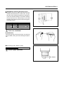
1
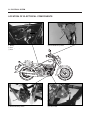
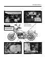
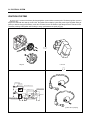
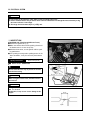
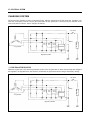
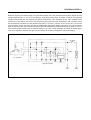
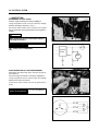
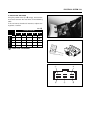
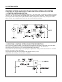
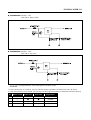
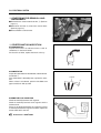
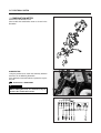
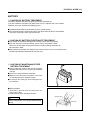
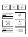
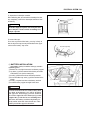
ELECTRICAL SYSTEM
CONTENTS
LOCATION OF ELECTRICAL COMPONENTS
5- 1
IGNITION SYSTEM
5- 3
CHARGING SYSTEM
5- 7
STARTER SYSTEM AND SIDE STAND
IGNITION INTERLOCK SYSTEM
5- 11
SWITCHES
5- 15
LAMP
5- 16
BATTERY
5- 18
FUEL SYSTEM
5- 21
5
5-1 ELECTRICAL SYSTEM
LOCATION OF ELECTRICAL COMPONENTS
①
③
④
②
① Battery
② Turn signal relay
③ Fuse
④ Front brake lamp switch
⑥
⑤
⑤ Rear brake lamp switch
⑥ Starter motor
ELECTRICAL SYSTEM 5-2
⑦
⑪
⑩
⑧
⑨
⑦ Ignition coil (NO.1 & NO.2)
⑧ C.D.I Unit
⑨ Regulator / Rectifier
⑩ Battery plus terminal
⑪ Battery minus terminal
CAUTION
Be sure not to misassemble the position of battery
plus & minus terminal.
⑫
⑬
⑫ Magneto
⑬ Gear position switch
5-3 ELECTRICAL SYSTEM
IGNITION SYSTEM
is started as the battery discharged ignition system without a contact point. The battery ignition system is
composed a rotor with five rotor tip, the D.C CDI, the ignition coil and battery. Ignite after permit signal at ignition timing of
pick-up as electric energy of this battery, occur the 1st electric current. Therefore a high voltage current is induced in the
secondary winding of the ignition coil resulting in strong spark between the spark plug gap.
�
C.D.I Unit
Magneto
�
SPARK PLUG
PLUG CAP
FRONT IGNITION COIL
IGNITION SWITCH
MAGNETO ASS’Y
REG
REC
CDI
Unit
BATTERY
REAR IGNITION COIL
SIDE STAND SWITHC
NEUTRAL SWITCH
Ignition coil & Spark plug
ELECTRICAL SYSTEM 5-4
◉ INSPECTION
� MAGNETO
Using the pocket tester, measure the resistance
between the lead wires in the following table.
Pick-up coil
G - L Approx 90�110 Ϊ
Charging coil
Y - Y Approx 0.6�0.9 Ϊ
Pocket Tester : 09900-25002
CAUTION
When mounting the stator on the magneto cover,
apply a small quantily of THREAD LOCK“1324
to the threaded parts of screws.
THREAD LOCK“1324”
WIRE COLOR
L
: Blue
G
: Green
Br
: Brown
B / Y : Black with Yellow tracer
O / B : Orange with Black tracer
G / W : Green with White tracer
B / W : Black with White tracer
W / L : White with Blue tracer
� CDI UNIT
Using the pocket (R × 1㏀ range), measure the resistance between the lead wires in the following table.
Unit : ㏀
� Probe of tester
� Probe of tester
1
2
3
1
─
∞
2
5 ~ 100
─
∞ 30 ~ 200 30 ~ 200 30 ~ 200 30 ~ 200 10 ~ 100
∞ 5 ~ 50 2 ~ 50 5 ~ 50 5 ~ 50 1 ~ 20
3
∞
∞ ∞
30 ~ 150 ∞
10 ~ 100 ∞
∞ ∞
10 ~ 50 ∞
4
5
6
7
8
10 ~ 100
─
4
5
6
7
8
5 ~ 50 2 ~ 50 5 ~ 50 5 ~ 50 1 ~ 20
∞ ─
∞ 30 ~150
∞ 10 ~ 100
∞ ∞
∞ 5 ~30
∞
─
∞
∞
⑤
⑧
④
①
∞
1 ~ 30 30 ~ 150 5 ~ 50
5 ~ 50
─
∞
∞
10 ~ 100 2 ~ 20
─
2 ~30 2 ~50 2 ~50
Pocket Tester : 09900-25002
⑦
⑥
∞
─
③
②
5-5 ELECTRICAL SYSTEM
CAUTION
� Pay caution as the numerical value differs a little according to the tester.
� Please remind that there may be defect which can not be identified even though the measurement by using
the tester indicates a low voltage.
� The range of measurement adjust a [ X 1㏀ ] unit.
◉ INSPECTION
� IGNITION COIL (Checking with Electro Tester)
● Remove the ignition coil ①, ②.
● Make sure that the three-needle sparking distance of
the electro tester is set at 8 mm (0.3 in).
● With the electro tester, test the ignition coil for sparking performance.
● If no sparking or orange color sparking occures in the
above conditions, it may be caused by the defective
coil.
Spark performance
②
①
Over 8 mm (0.3 in)
Electro tester : 09900-28107
① Front cylinder ignition coil
Cord
WARNING
Cord
Do not touch the wire clips to prevent an electric
shock when testing.
Cord
Cord
CAUTION
When using the electro tester, follow the instruction manual.
CAUTION
The ignition coil is marked the F for front, and
the R for rear.
If otherwise, it may occure severe damage to the
engine.
Spark
② Rear cylinder ignition coil
ELECTRICAL SYSTEM 5-6
� IGNITION COIL (Checking with Pocket Tester)
● A pocket tester or an ohm meter may be used,
instead of the electro tester. In either case, the ignition coil is to be checked for continuity in both primary and are secondary windings. Exact ohmic readings
are not necessary, but, if the windings are in sound
condition, their continuity will be noted with approximate ohmic values.
Ignition coil resistance
Primary
0.19�0.24Ϊ Tester knob indication × 1Ϊrange
Secondary
5.4�6.6 ㏀ Tester knob indication × 1㏀range
Check to attached plug cap
Pocket tester : 09900-25002
� SPARK PLUG
Clean the plug with a wire brush and pin. Use the pin to
remove carbon, taking care not to damage the porcelain.
● Check the gap with a thickness gauge.
Spark plug gap
0.7 � 0.8 mm
Thickness gauge : 09900-20806
0.7~0.8mm
5-7 ELECTRICAL SYSTEM
CHARGING SYSTEM
The circuit of the charging system is indicated in figure, which is composed of the AC generator, regulator / rectifier unit and battery. The AC current generated from the AC generator is converted by the rectifier and is
turned into the DC current, then it charges the battery.
IG. switch
Battery
Controlunit
A. C generator
L
O
A
D
Regulator / Rectifier
◉ FUNCTION OF REGULATOR
While the engine rpm is low and the generated current of the AC generator is lower than the adjusted voltage of
the regulator, the regulator does not function, incidentally the generated current charges the battery directly.
IG. switch
Battery
Controlunit
A. C generator
Regulator / Rectifier
L
O
A
D
ELECTRICAL SYSTEM 5-8
When the engine rpm become higher, the generated voltage of the AC generator also becomes higher and the
voltage between points � and � of the regulator according becomes high, and when it reaches the adjusted
voltage of the control unit, consequently the control unit becomes“ON”condition. On the“ON”condition of the
control unit, signal will be sent to the SCR (Thyristor) gate probe and SCR will become“ON”condition. Then
the SCR becomes conductive to the direction from point � to point �. Namely at the state of this, the current
generated from the AC generator gets through SCR without charging the battery and returns to the AC generator
again. At the end of this state, since the AC current generated from the AC generator flows into the point �, reverse
current tends to flow to SCR, then the circuit of SCR turns to“OFF”mode and begins to charge the battery again.
Thus these repetitions maintain charging constant voltage to the battry and protect it from overcharging.
IG. switch
Battery
Controlunit
A. C generator
Regulator / Rectifier
L
O
A
D
5-9 ELECTRICAL SYSTEM
◉ INSPECTION
� CHARGING OUTPUT CHECK
Start the engine and keep it running at 5,000 rpm.
Using the pocket tester, measure the DC voltage
between the battery terminal � and �.
If the tester reads under 13.5 V or over 16.0 V, check
the AC generator no-load performance and regulator /
rectifier.
CAUTION
When making this test, be sure that the battery is
full-charged condition.
Standard charge
IG. switch
13.5�16.0 V at 5,000 rpm
Pocket tester : 09900-25002
Regulator
Rectifier
Battery
� AC GENERATOR NO-LOAD PERFORMANCE
Disconnect the three lead wires from the AC generator terminal.
Start the engine and keep it running at 5,000 rpm.
Using the pocket tester, measure the AC voltage
between the three lead wires.
If the tester reads under 72V the AC generator is
faulty.
Standard NO-load performance of AC generator
72�99 V at 5,000 rpm
DCV
ELECTRICAL SYSTEM 5-10
★ REGULATOR / RECTIFIER
Using the pocket tester (X 1 Ϊ range), measure the
resistance between the lead wires in the following
table.
If the resistance checked is incorrect, replace the
regulator / rectifier.
Unit : ㏀
� Probe of tester
� Probe of tester
1
1
─1
2
OFF
3
4
5
2 OFF
3
OFF
OFF4
2
7~8
─
OFF
OFF
OFF
3
7~8
OFF
─
OFF
OFF
4
7~8
OFF
OFF
─
OFF
5
35 ~ 55
7~8
7~8
7~8
─
Pocket tester : 09900-25002
①
②
⑤
③
④
5-11 ELECTRICAL SYSTEM
STARTER SYSTEM AND SIDE STAND IGNITION INTERLOCK SYSTEM
◉ STARTER SYSTEM DESCRIPTION
The starter system consists of the following components : the starter motor, starter relay, clutch lever position
swith, C.D.I unit, side stand switch, gear position switch, starter switch, engine stop switch, ignition switch and battery.
Pressing the starter switch (on the right handlebar switch) energizes the starter relay, causing the contact
points to close, thus completing the circuit from the starter motor to the battery.
◉ SIDE STAND / IGNITION INTERLOCK SYSTEM DESCRIPTION
This side stand / ignition interlock system prevents the motorcycle from being started with side stand down.
The system is operated by an electric circuit provided between the battery and ignition coil.
The circuit consists of the C.D.I unit, neutral indicator light and switches.
The ignition coils will send voltage to the spark plugs dependant on what gear the transmission is in and whether the side stand is either up or down.
The gear positoin and side stand switches work together in this system.
The ignition coil work only in two situations as follows.
ELECTRICAL SYSTEM 5-12
� TRANSMISSION : Neutral - ON
Side stand - Down ( OFF )
� TRANSMISSION : Neutral - OFF
Side stand - Up ( ON )
is equipped with the side stand ignition interlock system.
1. If the transmission is in neutral, you can start the engine regardless of clutch lever and side stand.
2. If the transmission is not in neutral, you can only start the engine with pulling in clutch lever and side stand up.
No
Neutral switch
Clutch lever
Side stand
Engine Start
1
●
△
△
Possible
2
△
●
●
Possible
3
△
●
△
Impossible
4
△
△
●
Impossible
NOTE : ● - On or Up.
△ - Off or Down
5-13 ELECTRICAL SYSTEM
◉ STARTER MOTOR REMOVAL AND
DISASSEMBLY
● Disconnect the starter motor lead wire ①. (Refer to
page 3-3)
● With loosen the bolt ②, remove the starter motor.
(Refer to page 3-8)
● Disassemble the starter motor.
①
②
◉ STARTER MOTOR INSPECTION
� CARBON BRUSH
Inspect the brushes for abnormal wear, crack or
smoothness in the brush holder.
If the brush has failed, replace the brush sub assy.
� COMMUTATOR
Inspect the commutator for discoloration, abnormal wear
or undercut �.
If the commutator is abnomally worn, replace the armature.
When surface is discolored, polish it with #400 sand
paper and clean it with dry cloth.
� ARMATURE COIL INSPECTION
Check for continuity between each segment.
Check for continuity between each segment and the
armature shaft.
If there is no continuity between the segments or there
is continuity between the segment and shaft, replace the
starter motor with a new one.
Pocket tester : 09900-25002
Segment
�
ELECTRICAL SYSTEM 5-14
� STARTER MOTOR REASSEMBLY
Reassembly the starter motor. Pay attention to the following points :
● Reassembly the starter motor as shown in the illustration.
● Align the mark ① on the housing with the line ② on
the housing end.
②
①
5-15 ELECTRICAL SYSTEM
● Apply SUPER GREASE“A”to the O-ring ① and
remount the starter motor.
①
SUPER GREASE“A”
SWITCHES
Measure each switch for continuity using a tester. If any abnormality is found, replace the respectiveswitch assemblies
with new ones.
Pocket tester : 09900-25002
IGNITION SWITCH
ON
R
O
○
○
ENGINE STOP SWITCH
BW
BR
OFF
○
○
LOCK
○
○
HEADLAMP SWITCH
YW
Gr
○
○
○
ON
○
OFF
Y
HI
○
○
LO
○
○
○
OB
YG
○
○
HORN SWITCH
DIMMER SWITCH
YW
OB
STARTER SWITCH
O
○
O
W
ON
○
G
BW
○
○
OFF
TURN SIGNAL SWITCH
Lg
L
Sb
B
FRONT/REAR BRAKE LAMP SWITCH
○
○
O
WB
○
○
ON
PUSH
R
○
○
OFF
ELECTRICAL SYSTEM 5-16
LAMP
◉ HEADLAMP
◉ TURN SIGNAL LAMP
◉ TAIL / BRAKE LAMP
5-17 ELECTRICAL SYSTEM
◉ COMBINATION METER
Remove the combination meter.
Disassemble the combination meter as shown in the
illustration.
9
� INSPECTION
Using the pocket tester, check the continuity between
lead wires in the following illustration.
If the continuity measured incorrect, replace the respective part.
Pocket tester : 09900-25002
CAUTION
When making this test, it is not necessary to
remove the combination meter.
ELECTRICAL SYSTEM 5-18
BATTERY
◉ CAUTION OF BATTERY TREATMENT
The battery should be well taken care of because it emits flammable gas.
If you don’t follow the instruction in the below, there may be a explosion and severe accident.
Therefore, please pay attention to the following points.
● Prohibit positively battery from contacting to short, spark or firearms.
● The recharge of battery should be done in the wide place where the wind is well ventilated.
Please don’t recharge it at the sight of wind-proof.
◉ CAUTION OF BATTERY ELECTROLYTE TREATMENT
● Pay attention for the battery electrolyte not to stain the chasis or the humanbody.
● If be stain the chassis or the humanbody, at once wash a vast quantity of water.
When it be stained, clothes should come into being a hole or painting should take off.
Be cured from a doctor.
● When the battery electrolyte was dropped to the surface of land, wash a vast quantity of water.
Neutralize by hudroxide, bicarbonate of soda and so on.
◉ CAUTION OF MAINTENANCE FREE
BATTERY TREATMENT
● Do not remove the aluminum tape to seal the battery
electrolyte filler hole untill use as battery of completely
seal type.
● Do not use it except the battery electrolyte.
● When pour into the battery electrolyte, necessarily
use the electrolyte of the specified capacity.
● Do not open the sealing cap after recharge the battery eletrolyte.
● Filling electrolyte.
① The battery is puted on even land, remove the aluminum tape sealing.
② Remove the cap at the electrolyte container.
CAUTION
Do not remove the seal, not prick with sharp
thing.
Aluminum tape
Filler holes
5-19 ELECTRICAL SYSTEM
Cap
③ Pouring of battery electrolyte
When insert the nozzles of the electrolyte container into
the battery’s electrolyte filler holes, holding the container
firmly so that it cloes not fall.
Take precaution not to allow any of the fluid to spill.
CAUTION
There may be a case which can t pour the electrolyte if you put it into electrolyte container
slopely.
④ Confirmation of pour
Make sure that air bubbles are coming up each electrolyte container, and keep this position for about more
than 20 minutes.
CAUTION
If no air bubbles are coming up from a filler
port, tap the button of the two or three times.
Air bubble
Seal
ELECTRICAL SYSTEM 5-20
⑤ Separation of electrolyte container
After confirming that you entered the electrolyte into battery completely, remove the electrolyte containers from
the battery.
CAUTION
Draw the empty receptacle out slowly because
there may be a chance which remaining electrolyte vaporize.
⑥ Insert of the caps
Insert the cap into the filler holes, pressing it firmly so
that the top of the caps do not protrude above the up per
surface of the battery’stop cover.
Insert the caps firmly
◉ BATTERY INSTALLATION
s battery installation order pay attention
to following points :
① Romove the seat, right frame cover and battery support.
② Lay down (+) positive terminal of the battery at leftside
of the battery case (on the motorcycle).
③ Install (+) positive lead wire at the battery terminal.
④ Put on the rubber cap at the (+) positive terminal of the
battery.
⑤ Install (-) negative lead wire at the battery terminal.
⑥ Install the battery support and right frame cover.
CAUTION
If install first the lead wire at the battery then
lay down at the battery case, will be installed
the opposite direction[(+) positive terminal
face on the rightside of the motorcycle] as that
length of the (+) lead wire has no something extra.
This time, the battery could not lay down perfectly and to occur the short circuit etc. if the
battery install the opposite direction.
(-) Lead wire
⇒ Front side
5-21 ELECTRICAL SYSTEM
◉ ASSISTANCE RECHARGING
Use the battery that is maded after 2 years as the maintenance free battery.
Use the battery at condition of the high temperature.
Assistance recharging to the following points.
● The main principle of assistance recharging.
Assistence recharging from rule of electric current or
voltage, when the battery discharged.
● Do not assistance recharge except the right side
table.
● In times of recharging the battery, please do it at the
condition of removal of the lead wire.
Assistance Recharging
Standard
0.7 A ×5~10 hours
Fast
3A × 30 minutes.
WARNING
The firearm is strictly prohibited.
FUEL SYSTEM
◉ FUEL PUMP
● Remove the left frame cover. (Refer to page 6-3)
● Remove the fuel pump lead wire coupler �.
(Refer to page 4-2)
Using the pocket tester (X 1 Ϊ range), measure the
resistance between the lead wires in the following
table.
If the resistance checked is incorrect, replace the
fuel pump.
�
�
1.0�10.0 Ϊ (BW-BG)
Fuel pump resistance
Pocket tester : 09900-25002
◉ FUEL PUMP RELAY
● Remove the fuel pump relay coupler �.
(Refer to page 4-2)
Using the pocket tester (X 1 Ϊ range), measure the
resistance between the lead wires in the following
table.
If the resistance checked is incorrect, replace the
fuel pump relay.
Unit : Ϊ
� Probe of tester
� Probe of tester
1
2
3
4
1
─
∞
∞
2
∞
∞
∞
─
65 ~ 85
65 ~ 85
─
∞
∞
∞
∞
∞
─
3
4
Pocket tester : 09900-25002
①
②
N
④
O
COIL
COM
COIL
③