1
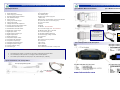
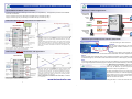
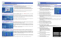
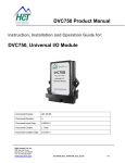
Electronic Solutions for Mobile, Industrial & Marine Applications High Country Tek, Inc. Electronic Pump Controller: epc-2 Mining & Exploration Open Loop control of single or dual coil valves, pumps & other equipment Agriculture Cranes & lifts Electronic Control Solutions for the Global Fluid Power Industry Refuse & Recycling Construction High Country Tek, Inc. ( HCT ) Off-Road vehicles Introduces the epc-2, our latest cost effective and simple answer to your dual channel driver needs. Forestry, Wood & Pulp Individual control of two (2) across center, open loop piston pumps or directional proportional valves from one robust unit. Reclamation & Salvage Oil Field & Sands Use our Free PC user set-up software for quick, easy and accurate configuration of each channels settings for any OEM electro-hydraulic products. Demolition Equipment Cooling Solutions Military Apparatus HCT Product Sales and Support: Specialty Use Remote Control Power Generation Designed for use in extreme environments, fully sealed and complete with CE compliance makes this an attractive universal solution that can be easily used in mobile or industrial global applications. For a full list of authorized distributors worldwide, please visit: www.hctcontrols.com/distributors/index.htm Emission Controls epc-2 Product Features: Integrated Drivers Valve & Pump Controls To discuss anything in this brochure, order product, get price and delivery or book a training course, please contact our customer service department through E-mail at: [email protected] High Country Tek, Inc. www.hctcontrols.com 021-00222, Rev A (epc-2-June-A10.pub/GG/2011) 208 Gold Flat Court Nevada City, CA, 95959 Tel: (1) 530 265 3236 Fax:(1) 530 265 3275 Copyright © High Country Tek, Inc. - 2011 8 Operates with all major OEM electro-hydraulic valve and pump equipment Dual channel open loop controller ready for voltage or mA analog command signals Sealed & protected to >IP68 ( NEMA 6P ) Environmentally hardened by ’Solid’ potting with flame retardant materials SAE-J1939 & HCT-CAN communication protocols Full CE compliance for confident global application on all mobile equipment Patented Intella™ system configuration software for fast implementation** Industry standard Cinch, Metripack Series 150 - 30 way connectors used Comprehensive on-line literature, manuals, user guides and application information www.hctcontrols.com ** - Expert mode access Copyright © High Country Tek, Inc. - 2011 Electronic Controller Solutions for the Global Fluid Power Industry epc-2 Specification: Electronic Controller Solutions for the Global Fluid Power Industry epc-2 Module Mechanical Details: 1. Module size/format: High Country Tek Inc. proprietary format 2. Design Standards: Full CE classification 3. Power Supply type and range: 10 to 32VDC (max) 4. Recommended module protection: 5A AGC fuse in power supply line 5. User stabilized voltage: + 5VDC ±10% epc-2 Module Connection Details: epc‐2 Connector Designation Tables 30 Pin Metri‐Pak Connector ( Male, Plug ) PIN L1 L2 L3 Name TXD RXD RTS M2 M3 PWR COM RS232 GND/0V PWR COM Channel #2 Command GND/0V 6. Output current: 500mA (max) - Current limited, short circuit protected 7. Analog Input number & type: 2x Inputs / DC Volts or Current loop (mA) 8. Analog input values: 0 to +5v or 0 to 20mA 9. Voltage Command I/P Impedance: 10 KOhm 10. Current command shunt resistor value: 100 Ohms 11. Global Enable / Dis-able input: 1x ON/OFF - see note below 12. Global Enable / Dis-able values: 0V to +V Power supply max - see note below 13. Digital input number & type: 2x ON/OFF inputs / DCV - level shift 14. Digital input values: 0V to +V Power supply max 15. Digital output number & type: 2x High Side / ON/OFF level shift 16. Digital output values: 0 to module supply voltage -0.5VDC For a 1/4-20 bolt, SAE Grade 5 17. Digital output range: 0 to 3 amp max 18. Proportional Output number: 2x PWM DRY Torque: 8 Ft-Lbs Lubricated Torque: 6.3 Ft-Lbs 19. Proportional O/P Protection: Open and short circuit protection 20. Proportional output range: 0 to 3 amp max N2 N3 P1 Function Transmit RS232 Data ‐ Pin 'C' Receive RS232 Data ‐ Pin 'A' Request To Send ‐ RS232 Pin 'D' PWR COM Ground / 0V / Signal Common PWR COM Ground / 0V / Signal Common UNI‐1 Channel #1 Command I/P PIN Name P3 R1 PWR COM Channel #1 Command GND/0V UNI‐2 Channel #2 Command I/P Function R3 +5V USER +5V regulated user output S2 S3 T1 T2 DIG‐1 DIG‐2 HS‐1 HS‐3 Global Enable I/P Digital I/P #2 ( Turns ON W3 ) Channel #1 Coil A Channel #2 Coil A L M N P R 21. Operating Temperature range: -40C to +85C 22. Storage temperature range: -40C to +100C 23. Ingress protection rating: IP 69 / NEMA 6P 24. Connector type: Cinch. Metri-Pack 150 series - 30 way male IMPORTANT NOTE: Function Digital I/P #3 ( Turns ON X3 ) Chanel #1 PWM O/P Chanel #2 PWM O/P Digital O/P ( from Digi 2 I/P ) Channel #1 Coil B Channel #2 Coil B Digital O/P ( from Digi 3 I/P ) +V Supply Power Input +V Supply Power Input S T W X Y View looking at module male 30 way connector Recommended tightening torques for the securing bolts are as follows: 999‐10076 Connector Details RS232 (PC) to epc‐2 Communication Cable evc‐2 PIN L1 L2 L3 M2 REMOTE ENABLE Important Note: The Enable input is DIGI 1 ( connector pin S2 ) and is configured to be active HIGH The user MUST pull the input ‘S2’ to +V supply to allow normal operation. The enable input is failsafe, with the input pin ‘S2’ pulled LOW ( 0V ) internally. epc-2 accessories - PC set-up cables: PC to epc-2programming Cable: HCT Part Number: 2 Name DIG‐3 PWM‐1 PWM‐2 HS‐5 HS‐2 HS‐4 HS‐6 +PWR IN‐1 +PWR IN‐2 1 2 3 epc-2 LED operation and description: 999-10075 PIN T3 W1 W2 W3 X1 X2 X3 Y1 Y2 www.hctcontrols.com 7 Name TXD RXD RTS PWR COM Function 999‐10076 Transmit RS232 Data ‐ Pin 'C' C Receive RS232 Data ‐ Pin 'A' A Request To Send ‐ RS232 Pin 'D' D RS232 GND (0V) B Electronic Controller Solutions for the Global Fluid Power Industry Electronic Controller Solutions for the Global Fluid Power Industry epc-2 additional ON/OFF control features: Dual Path / Channel applications: To allow low level signals to drive high current loads ( i.e. lamps/alarms ) , the application provides 2 extra ON/OFF drives for convenience: Digi 2 ( Connector pin S3 ) is internally connected to HS 5 ( Connector pin W3 ) Digi 3 ( Connector pin T3 ) is internally connected to HS 6 ( Connector pin X3 ) Command I/P Channel # 1 Channel # 1 Single or bi-directional output Voltage or Current Dual Path with Single coil connections and applications: Digital I/P #1 2x Single Coil configuration Common Enable/Disable High Current O/P # 1 REMOTE ENABLE : See note on page 3 of this manual Digital I/P #2 High Current O/P # 2 epc-2 Command I/P Channel # 2 Channel # 2 Single or bi-directional output Voltage or Current This option allows each input to control one output channel and take full advantage of the 10 bit (1024 steps) resolution offered by the epc-2 controller. The dead band is internally set to approx. ±5% of the chosen command, shown here at 250mV for a 5V input and is to allow for any mechanical wear, tolerance or movement in the command potentiometer or joystick. When using 4 to 20mA, the deadband is still ±5% which equates to approx 0.8mA Configuration shown using 1x potentiometer or joystick with internal regulated +5V and 1x externally provided 4-20mA command input to control 1x valve coil per channel. Dual Path with Dual coil connections and applications: 2x Dual Coil configuration Dual Path epc-2 Graphical User Interface (GUI) Guide: Click the following for these functions: Technical: This will open a PDF version of this manual that is installed with the Graphical User Interface software so it is available as a reference at all times. Contact: This opens the users E-mail program and enters the HCT address and subject ready for the user to communicate and send whatever information required to HCT. About: Opens the GUI page displayed below, giving important information on the module and versions of software that may be needed during any conversations or E-mail with HCT technical or field support personnel. REMOTE ENABLE : See note on page 3 of this manual Help: This opens a PDF document on the epc-2 going into more details on the programming that the user can utilize to modify this original application software program if required ( GUI will NOT reflect any user changes made ) epc-2 Configuration shown using 1x potentiometers or joysticks with internal regulated +5V and 1x externally provided 4-20mA command input to control 2x valve coil per channel. 6 This option allows each input to control one output channel but two valve coils. The input command signal is configured such that at ~mid-value, both coils are OFF. The command dead-band is internally set to ±5% as before and as soon as this level is seen, the output immediately jumps to the relative Imin setting and smoothly proceeds from there to Imax for max command. Coil A command is from ~mid value to +max value ( i.e. 2.5V to +5VDC ) while Coil B command is from ~mid value to +0 value ( i.e. 2.5V to 0V ). www.hctcontrols.com The ‘Miscellaneous Information’ page shows the module serial number as well as all versions of the software and GUI being used. This information may be asked for by HCT support personnel during any contact you require for help and guidance e.t.c. The other information shown on this page is the HCT mailing address and also the direct E-mail to our customer support group. There is also a live link ( if PC is connected to the Internet ) to the HCT website where extra information as well as the latest literature and product details can be found as required. Clicking the ‘Back >>‘ button will take the user to the previous screen. 3 Electronic Controller Solutions for the Global Fluid Power Industry epc-2 Graphical User Interface (GUI) Guide: 1. 2. 3. 4. 5. Electronic Controller Solutions for the Global Fluid Power Industry epc-2 Graphical User Interface ‘Fine Settings Page’ Guide: Install the epc-2 Graphical User interface program onto Windows O/S PC or laptop or TekBook by following on-screen instructions. Connect epc-2 controller to suitable power supply. Connect RS232 communications cable to epc-2 and Windows PC noted in 1. Locate the program in the ‘START’ menu and click to open the program. Once communication has been established, the program will open with the screen shown to the left and attempt to make communications with the epc-2 module. NOTE: As required, messages will be displayed to alert the user to issues or items that need attention. Typically GREEN message backgrounds are good while bright RED should be taken as a warning or notice of a setting or state that could need attention. 1. Channel X coil 1A Imin Out Current ( mA ): This is the minimum current value that that will be sent to valve coil 1A when the command signal is approximately ± 5% of 2.5V (~125mV) 2. Channel X coil 1A Imax Out Current (mA): This is the maximum current value that that will be sent to valve coil 1A when the command signal is at approximately ±100% i.e. 0% command = Coil B at 100%, 50% command - Both coils OFF, 100% command = Coil A at 100%. 3. Channel X coil 1B Imin Out Current (mA): Same function and action as noted in item 1. above This screen is intended to give the user a ’Dashboard’ overview of the controller settings in one easy to read screen. The ‘command input’ and ‘output current’ for each channel can be seen while also observing the status of the RS232 communications between the PC and the module. Top right of the screen is also a display box for the module supply voltage and actual internal temperature reading displayed in real time. 4. Channel X coil 1B Imax Out Current (mA): Same function and action as noted in item 2. above ‘Fine Tune’ page in PC user interface program 5. Channel X coil 1A Ramp UP time ( Seconds ): This is the total time taken for the relative output current to go between the Imin and Imax settings for a 0% to 100% command input. The time is scaled for 0 to 100% command meaning that if the command goes from 50% to 100% the time taken will be 50% of the seconds set. 6. Channel X coil 1A Ramp DOWN time ( Seconds ): Clicking the ‘Next >>‘ button will move the user to the next screen or clicking ‘Exit’ will close the interface and return the user to Windows desktop. The ‘Configuration Page’ shown here, allows the user to set the basic input command type to either DC Voltage ( 0 to +5VDC ) or to Current ( 4 to 20mA ) and how many coils will be connected to each output. This process is important as selecting the single coil output type will scale the 0 to 100% command input across only one output while selecting a dual coil output type will split the command across coil A and Coil B, effectively halving the command resolution. Clicking the ‘Next >>‘ button will move the user to the next screen or clicking ‘<< Back’ will take the user to the previous screen. This is the total time taken for the relative output current to go between the Imax and Imin settings for a 100% to 0% command input. The time is scaled for 0 to 100% command meaning that if the command goes from 100% to 50% the time taken will be 50% of the seconds set. 7. Channel X coil 1B Ramp UP time ( Seconds ): Same function and action as noted in item 5. above 8. Channel X coil 1B Ramp DOWN time ( Seconds ): Same function and action as noted in item 6. above 9. Channel X Dither Amplitude ( 0-100%): This is the level of ‘Dither’ signal applied to the output current as a fixed percentage - i.e. if you set 50% here, the amplitude will be ratiometric over the entire PWM output range of 5 to 95 PWM. Valve OEM’s usually recommend a % level here If no information is available, set to 30% for initial trials and optimize at later stage if needed. Parameter 10. Channel X Dither Frequency ( Hz ): The ‘Fine Tune Page’ offers the user options to customize each channel and to ensure that the valve or pump being controlled, acts as desired and is optimized. As long as the user is connected to a epc-2 module, any changes made here are transmitted immediately to the module and will change the characteristic in the non-volatile memory updating the settings and making them the new levels even after power ON/OFF, so care should be taken to make small changes while also making sure that the correct parameter is being altered. User editable value box’s have a blue background with yellow text. Each window has ‘min’ and ‘max’ limits pre-set so prevent the user from entering a value that may cause issues. Clicking the ‘Dashboard‘ button will move the user back to the observation screen or clicking ‘<< Back’ will take the user to the previous screen. 4 This is the ‘Dither’ frequency that will be on the PWM output. Again, Valve OEM’s usually recommend frequency here, if no information is available, initially set 150Hz for cartridge and smaller valves and 100Hz for larger industrial valves. 11. Channel X Command Min: Value sets the Max command input allowed 12. Channel X Command Mid: Value sets the Mid command for changeover in dual coil mode, ignored for single coil mode 13. Channel X Command Max: Channel 1 coil 1A Imin out current Channel 1 coil 1A Imax out current Channel 1 coil 1B Imin out current Channel 1 coil 1B Imax out current Channel 1 coil 1A Ramp up Channel 1 coil 1A Ramp down Channel 1 coil 1B Ramp up Channel 1 coil 1B Ramp down Max Value Min Value 3000mA 3000mA 3000mA 3000mA 65 sec 65 sec 65 sec 65 sec 10% ‐100% in 10% increments 33,45,50,55,76,10 0,125,142,200, 250, 333 & 500 Hz 0mA 0mA 0mA 0mA 0sec 0sec 0sec 0sec Channel 1 Command Min 5.0V 0V Channel 1 Command Mid 5.0V 0V Channel 1 Command Max 5.0V 0V Channel 1 coil 1A Dither Amp Channel 1 coil 1A Dither Freq Value sets the Mid command allowable Action Text Limits Input to 5v RED Warning out of range box RED Warning out of range box Table guide showing user interface alarm annunciations and Max values or increments for various set-up parameters 5