1
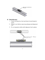
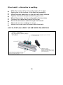
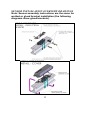
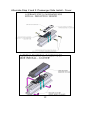
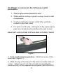
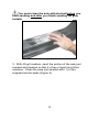
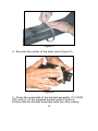
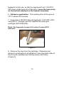
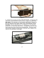
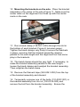
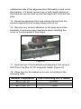
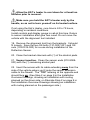
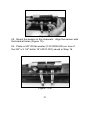
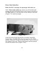
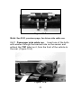
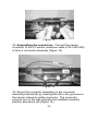
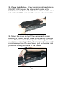
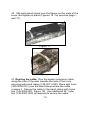
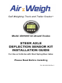
Self-Weighing Truck and Trailer Scales™ Model AW5800 On-Board Scales STEER AXLE DEFLECTION SENSOR KIT INSTALLATION GUIDE For Use on Vehicles with Steel Spring Steer Axles Please Read Before Installing PN: 901-0059-000 Rev 6 Limited Warranty For product failures due to material or manufacturing defects, Air-Weigh will replace or repair all air suspension components for up to 3 years from shipment date to the end-user Air-Weigh customer. These three-year components include: Displays, ComLinks, Air Sensors, Power Cables, Air Sensor Assemblies, Air Sensor Harnesses, and all other associated external components. Deflection Sensors have a 2-year warranty. Air-Weigh assumes no responsibility for administering warranty claims directly with any third party end users. The responsibility of Air-Weigh under this warranty is limited to the repair, replacement, or credit of the defective part or assembly. This warranty does not cover incidental or consequential damage to persons or property caused by use, abuse, misuse, or failure to comply with installation or operating instructions. This limited warranty does not apply to any product that has failed due to accident, abuse, alteration, installation not consistent with printed installation instructions, improper maintenance, improper operation, or as a result of system integration or installation not explicitly approved in writing by Air-Weigh. Air-Weigh and its resellers shall have no responsibility or liability for damages if the purchaser or any other person alters the vehicle incorporating Air-Weigh products. This limited warranty shall not apply to any product that has been repaired or altered by anyone not employed by Air-Weigh or not operated in accordance with the manufacturer’s printed material delivered with this product. Air-Weigh hereby expressly disclaims any and all implied warranties of any type, kind of nature whatsoever, particularly any implied warranty of merchantability or fitness for a particular purpose not expressly stated by Air-Weigh in its printed material delivered with its products. Some states do not allow the exclusion or limitation of incidental or consequential damages. If such laws apply, the limitations or exclusions contained in the terms and conditions of this Warranty may not apply. This warranty gives you specific legal rights and you may also have other rights, which vary state to state. May be covered by U.S. Patent Nos. 4832141, 5478974, 5780782, Foreign Patent Nos. 623635, 1305191, 260494, 677998, 2122766, 625697 Copyright © 2004, 2006, 2007 by Hi-Tech Transport Electronics, Incorporated. All rights reserved. Air-Weigh®, ComLink™, WireLink™, Weight Gauge™, and Hi-Tech Transport Electronics are registered trademarks of HiTech Transport Electronics, Incorporated. Other brand, product, or service names listed in this document are the trademarks or registered trademarks of their respective holders. Information contained in this literature was accurate at time of publication. Product changes may have been made after copyright date that are not reflected. 2 Procedure for Warranty Claims 1. In the event Air-Weigh requests to examine product prior to disposition, OR for repairs or replacements, Air-Weigh requires a Return Material Authorization (RMA) number to be issued before the item is returned. Contact Customer Support Department at (888) 459-3247 for an RMA number. Please reference this RMA number in all correspondence. 2. Claimed items shall be shipped freight pre-paid to: Air-Weigh, Customer Support Department, 1730 Willow Creek Circle, Eugene, Oregon 97402, USA. The Air-Weigh RMA number shall appear on the outside of the return packaging. 3. Air-Weigh shall examine returned material within 30 days after receipt, or sooner if mutually agreed upon. If Air-Weigh determines that the part or assembly was defective in material or workmanship and within the warranty period, Air-Weigh will repair or replace the part or assembly and return freight pre-paid. In the event Air-Weigh determines that the part or assembly cannot be repaired or replaced and is within the warranty period, a credit not to exceed the purchase price will be issued to the AirWeigh customer. 4. Air-Weigh Accounting will process a credit memo and notify the AirWeigh customer by email or fax. The Air-Weigh customer will process a corresponding debit memo and notify Air-Weigh Accounting. 5. If the part or assembly received by Air-Weigh does not meet the requirements of the warranty program set forth above, at the Air-Weigh customer’s request the part or assembly will either be discarded, returned freight collect, or repaired or replaced at the Air-Weigh customer’s expense and returned freight collect. 1730 Willow Creek Circle • Eugene, Oregon 97402-9152 USA P.O. Box 24308 • Eugene, Oregon 97402-0437 USA Telephone (541) 343-7884 • Order Desk (888) 459-3444 Customer Support (888) 459-3247 • FAX (541) 431-3121 Hours of Operation: Mon-Fri, 8am – 5pm, Pacific Time www.Air-Weigh.com 3 Table of Contents INTRODUCTION .........................................................5 Parts & Bill of Materials Referenced In This Guide.6 TOOLS REQUIRED ....................................................7 SENSOR INSTALLATION OVERVIEW ......................8 SENSOR INSTALLATION OVERVIEW DRAWINGS11 BRACKET AND SENSOR INSTALLATION INSTRUCTIONS ........................................................ 13 Deflection Sensor Specifications ........................... 32 APPENDIX A: ........................................................... 33 4 INTRODUCTION The Air-Weigh Steer Axle Deflection Sensor is a major component of several Air-Weigh Tractor/Truck Scale kits. Properly installed, it allows the user to determine the weight on a spring-ride steer axle. For the most accurate weighing, follow the installation procedures in this guide exactly. See the user manual included with your kit for complete scale installation, calibration and operation. You must have the ComLink and display installed and powered to be able to check A/D readings using the DIAGNOSTICS menu in the display. Alternately, you can also use the optional Deflection Sensor Test Tool to get measurements directly at the sensor. Do not move the vehicle until after alignment tool removal, Step #19. Do not calibrate for weighing operations until after the vehicle has been in normal operation for a minimum of one week following sensor installation, to allow the sensor to seat. The heavy calibration must be done using a maximum vehicle load. During calibration, the steer axle weight at a heavy load must exceed the steer axle weigh an empty load. 5 Parts & Bill of Materials Referenced In This Guide Part Number 010-0069-000 010-9093-002 Description SENSOR INSTALLATION KIT DEFLECTION SENSOR, INTERNAL AMPLIFIER, METRIPACK 150, FEMALE, 12" Qty 1 1 Bill of Materials for Sensor Installation Kit 010-0069-000 Part Number 110-0080-000 111-0001-000 120-0066-000 133-0009-000 139-0011-000 145-0007-000 145-4552-001 350-0035-000 350-0038-000 350-0039-000 380-0004-001 901-0059-000 Description Qty TAB, SS, CONN MOUNT, DFL SNSR 1 BRKT ASSY,DEFL SENSOR, BONDED (see below) 1 COVER ASSY, DEFL SNSR W/ “CAUTION" DECAL 1 WASHER-FLT, .375 ID, PFC 9, THK, USS, STL, Y ZN PL 4 CLAMP,BAND,4.5-6.5IN DIA,21IN LONG 5 CABLE TIE, .30"X24", NYLON, BLKUV 6 NYLON TIE, 7", T-50, NYLON, BLK 2 IPA, PREP PADS 6 EPOXY, 3M, DP-420, 37 ML 1 STATIC MIXER NOZZLE, 6" 1 SPLIT LOOM,0.50, FT .09 INSTLL MANL, DEFL SNSR, STR AXLE 1 Note: Teromix-6700 may be used as an alternative to the 3M epoxy PN 350-0038-000, see Appendix A for details. Bill Of Materials for Bracket Assembly 111-0001-000 Part Number 110-0073-001 110-0079-000 131-0037-001 132-0014-000 350-0040-000 350-0041-000 Description Qty ALIGNMT TOOL,DEFL SNSR 1 MTG BRKT,DT,GLUED,7 DEG,2"W 2 SCR-MACH,.375-24X2.25 HEX HD, STL, GR 8, Y ZN PL 2 NUT-HEX, .375-24, GRD 8, Y ZN PL 2 TAPE, VINYL, FOAM, 1/4", CLOSED CELL, FT .22 TAPE, FILAMENT, 2.36” – 3” WIDE, FT .22 Optional items: Part Number 010-0071-000 395-0043-000 Description INSTALLATION KIT, DEFLECTION SENSOR, BONDED MOUNT TOOL, TESTER, DEFLECTION SENSOR Includes Application Note 901-0083-000 for test fixture operation. 6 TOOLS REQUIRED Sander with 40-grit medium Chalk or permanent marker Flat blade screwdriver 9/16” wrench Torque wrench, 20-80 ft-lb range 9/16” socket OPTIONAL 3M EPX Plus II Manual Applicator KAT’S by Five Star K1153 magnetic heater Deflection Sensor Install Test Fixture NOTE: The Deflection Sensor (DS) Installation Kit, Air-Weigh P/N 010-0071-000, which can be purchased separately, includes both the EPX Applicator P/N (010-0021-000) and the KAT’S heater P/N (010-0070-000). The Deflection Sensor Install Test Fixture, Air-Weigh P/N 395-0043-000, can be used to measure A/D readings of the deflection sensor without connection to the AW5801 Truck Scale Comlink. NOTE: A/D refers to the analog-to-digital conversion of the sensor reading. 7 SENSOR INSTALLATION OVERVIEW Welded Install Note: Welding is the preferred method of installing the deflection sensor brackets. The following instructions are applicable to all steer deflection sensor installs where the sensor brackets will be welded to the steer axle. The balance of the install should be completed per user’s manual included with your kit. Material Needed Alcohol or degreaser Small grinder or sand paper C-clamp ARC or wire welder A. Prepare Axle for welding and bracket placement 1. Clean center of axle in preparation for sensor bracket placement. a) Measure and mark center of axle. b) Clean axle on both sides of the center mark in an area wide enough to encompass brackets. 1) Use alcohol or degreaser to remove grease. 2) Sand off any paint in the area. 2. If not already assembled, attach alignment tool to the two brackets 3. Remove foam strip from the bottom of bracket. 4. Center bracket on axle 5. Use C-clamps to hold bracket in place. 6. Weld bracket (see Step B). Allow to cool before removing clamps and alignment tool. 8 B. Weld Bracket 1. Weld a full bead on front and back of each bracket piece. 2. Allow to cool before removing clamps and alignment tool. 3. Do not operate vehicle with alignment tool in place. 9 Glue Install – alternative to welding Mark the center of the axle and prepare it for glue. Apply glue to the bottom of the bracket assembly. Mount bracket assembly on the axle with band clamps. Tighten the band clamps and let the glue cure. Mount the sensor and mounting tab to the brackets. Connect the cables and mount to the tab. Route the extension cable through the firewall. Check for sensor readings in range. Mount the cover over the sensor and brackets. GLUE INSTALLATION OVERVIEW DRAWINGS 10 SENSOR INSTALLATION OVERVIEW DRAWINGS Note: Sensor assembly instructions are the same for welded or glued bracket installation (the following diagrams show glued brackets). 11 Alternate Step 2 and 3: Passenger Side Install - Cover. 12 Air-Weigh recommends the following install procedure: 1. Weld or glue sensor bracket to axle. 2. While weld is cooling or glue is curing, mount in-cab components. 3. Continue deflection sensor install after weld has cooled or glue has cured. 4. For glue mounts only - when glue is dry, spray epoxy paint over brackets where adhered to axle to seal. BRACKET AND SENSOR INSTALLATION INSTRUCTIONS Figure 1 1. Axle and bracket preparation. Mark the center of the steer axle (Figure 1). 2. Mark the top of the axle at 2 3/8 inches on either side of center. Clean the entire 4 3/4 inch wide area inside the marks with (2) of the supplied alcohol pads (350-0035-000). 13 You must clean the axle with alcohol before you start sanding and after you finish sanding for glue installs. Figure 2 3. With 40-grit medium, sand the portion of the axle just marked and cleaned so that it is free of paint and other residues. Clean the area just sanded with (1) of the supplied alcohol pads (Figure 2). 14 Figure 3 4. Re-mark the center of the steer axle (Figure 3). Figure 4 5. Clean the underside of the bracket assembly (111-0001000) with (1) of the supplied alcohol pads (Figure 4). Ensure that the bracket assembly bolts are only loosely 15 fastened to the nuts, so that the alignment tool (110-0073000) has a slight amount of free play. Leave the foam strip on the bottom attached to the bracket assembly. 6. Adhesive application. The working time of the glue at 73°F is about 20 minutes. 7. Assemble a 3M EPX Manual Applicator (010-0021-000) using the 2:1 plunger and the supplied duo-pak glue cartridge (350-0038-000). Note: See Appendix A page 30 if using Teromix-6700 adhesive. Figure 5 8. Remove the cap from the cartridge. Dispense and discard a small amount of adhesive to be sure both sides of the duo-pak cartridge are flowing evenly and freely. (Figure 5) 16 Figure 6 9. Attach the mixing nozzle (350-0039-000). Following the adhesive manufacturer’s instructions, apply the adhesive liberally to the bottom of the bracket assembly (Figure 6). Do not remove the foam strip from the bottom of the bracket. Ensure that there is no adhesive in the bracket channels or mounting bolt holes. Completely remove any that may have been put there accidentally. Remove and discard the mixing nozzle when finished, and replace the cap on the adhesive cartridge. Figure 7 17 10. Mounting the brackets on the axle. Place the bracket assembly in the center of the axle (Figure 7). Make sure the center mark on the alignment tool lines up with the center mark on the axle. Figure 8 11. Run a band clamp (139-0011-000) through the slot in the bottom of each bracket (Figure 8, previous page). Tighten the band clamps very firmly to secure the brackets in place, ensuring that the bracket assembly remains parallel to the axle length and the alignment tool has some play in the brackets. 12. The band clamps should be very tight. If necessary, to make the bracket assembly parallel to the axle length, loosen the band clamps and readjust the bracket assembly. Then retighten the band clamp. 13. Remove the filament tape (350-0041-000) from the top of the bracket assembly and discard. 14. Temporarily unscrew one of the bolts (131-0037-001) in the bracket assembly from its nut (132-0014-000) and remove the bolt from the bracket assembly. Ensure the 18 unfastened side of the alignment tool lifts easily in and out of the bracket. If it binds, loosen one or both band clamps so the brackets can be lined up and the alignment tool has free play. 15. Reset the alignment tool and restore the bolt into the bracket assembly and loosely fasten with its nut. 16. Remove any excess adhesive in the area around the brackets, to ensure proper clearance when installing the cover in the procedure’s final steps. Figure 9 17. Heat the top of the brackets and alignment tool using a KAT’S by Five Star K1153 magnetic heater (Figure 9). 18. Allow time for the adhesive to cure, according to the following table: Ambient Temperature 50° F (10° C) 68° F (20° C) 86° F (30° C) Cure Time using KAT’S Heater 6 Hours 3 Hours 1 Hour 19 Allow the KAT’s heater to cool down for at least ten minutes prior to removal. Make sure you hold the KAT’s heater only by the handle, so as not to burn yourself on its heated surface. If not using the Kat’s Heater, cure time is 24 to 72 hours, depending on ambient conditions. Install comlink and display gauge in cab at this time. Return to sensor installation after glue has cured. Do not move the vehicle with the alignment tool installed. 19. Remove the alignment tool from the brackets. It should fit loosely. Save the two 3/8 bolts (131-0037-001) and 3/8 nuts (132-0014-000) for re-use during installation of the Deflection Sensor. 20. Clean the bracket channels with (1) of the alcohol pads. 21. Sensor insertion. Clean the sensor ends (010-9089000) with the (1) remaining alcohol pad. 22. Insert the sensor with its cable extending away from the side of the vehicle where you’ll route the sensor extension cable to the firewall. The “TOP” lettering at the opposite end should face up. (See Step 2 on page 8 in the Installation Overview Drawings, showing an installation with routing planned on the driver side; or Alternate Step 2 on page 9 in the Installation Overview Drawings showing an installation with routing planned on the passenger side.) 20 Figure 10 23. Mount the sensor in the channels. Align the sensor with the bracket holes (Figure 10). 24. Place a 3/8" ID flat washer (133-0009-000) on one of the 3/8" x 2 1/4" bolts (131-0037-001) saved in Step 16. Figure 11-A 21 Driver Side Cable Run Note: See 26-P, next page, for passenger side cable run. 25-D. Driver side cable run. Insert one of the bolts with washer through the bracket hole on the sensor end without the TOP label on it, from the front of the vehicle to the rear. (Figure 11-A, previous page) Figure 11-B Insert the second bolt through the connector assembly bracket tab (110-0080-000), then through the 3/8” ID flat washer. Slide bolt through the bracket hole, from the front of the vehicle to the rear. Ensure the tongue and tab extend around the sensor end. (Figure 11-B) 22 Figure 12-A Note: See 25-D, previous page, for driver side cable run. 26-P. Passenger side cable run. Insert one of the bolts with washer through the bracket hole on the sensor end without the TOP label on it, from the front of the vehicle to the rear. (Figure 12-A) Figure 12-B 23 Place a 3/8” ID flat washer on the second bolt. Slide the second bolt through the bracket holes from the front of the vehicle to the rear. Place a washer, then connector assembly bracket tab (110-0080-000), on bolt. Ensure the tongue and tab extend around the sensor end. (Figure 12-B, previous page) 27. Place a hex nut on each bolt and hand-tighten. When tightening the sensor mounting bolts, you must torque the nut, not the bolt head. 28. Tighten the nut on the cable end of the sensor to 25 ftlbs of torque. Use torque wrench on the nut, not on the bolt head. Torque will be increased in Step 30. 29. Tighten the nut on the non-cable end of the sensor to 25 ft-lbs of torque. Use torque wrench on the nut, not on the bolt head. Torque will be increased in Step 31. 30. Tighten the nut on the cable end of the sensor to 50 ftlbs of torque. Use torque wrench on the nut, not on the bolt head. 31. Tighten the nut on the non-cable end of the sensor to 50 ft-lbs of torque. Use torque wrench on the nut, not on the bolt head. Check A/D readings at this time using the display in the cab (comlink and sensor must be connected to display and powered up) or deflection sensor install test tool per Step 37. NOTE: A/D refers to the analog-to-digital conversion of the sensor reading. 24 If the reading is below 500, or there is no reading at all follow these steps to exert a pre-load on the sensor: a. Loosen the nut on the non-cable end of the sensor. b. Insert a wedge (i.e. a flat-blade screwdriver) under the non-cable end of the sensor until an appropriate A/D reading is reached, for example: Steer – 500 - 1185 c. Tighten nut on non-cable end of sensor to 25 ft-lbs. If A/D readings are still within range, remove wedge and check A/D readings. Proceed with Step 30. If the reading is above 1185: d. Loosen the nut on the non-cable end of the sensor. e. DO NOT WEDGE the sensor. f. Tighten nut on non-cable end of sensor to 25 ft-lbs. Check A/D readings; if they are below 500 repeat Steps 31 a - c. If they are above 1185, repeat Steps 31 d - f. If within range proceed with Step 32. If using the Deflection Sensor Install Test Fixture: Before connecting the sensor to the sensor extension cable, check A/D readings and adjust if necessary at this time according to Application Note 901-0083-000 (included in tester kit) and Step 37 (see page 25). Otherwise, proceed with next step of installation. 25 Figure 13 32. Assembling the connectors. Connect the sensor connector to the 15' sensor extension cable (014-1500-028) to form a connector assembly (Figure 13). Figure 14 33. Mount the connector assembly on the connector assembly bracket tab by inserting the tab in the grooves on the sensor extension cable connector. The connector grooves are on the side opposite the installed connector position assurance tab (Figure 14). 26 34. Route the sensor extension cable across the axle, along the frame, and through the cab firewall. NOTE: Be sure to leave enough slack in the cable between the axle and frame to allow for axle movement. 35. When the AW5801 Truck Scale ComLink is mounted, connect the sensor extension cable to the appropriate AW5801 port as follows: For a single Drive Axle sensor, connect Steer Axle sensor to AW5801 Port B; For dual Drive Axle sensors, connect Steer Axle sensor to AW5801 Port C. For more information about sensor port connections, see Important Installation Instructions: Installing Sensor(s) for This Kit (901-0039-000) included in the Truck Scale kit documents package. 36. Refer to the Air-Weigh manual for the AW5800 Truck Scale included in your kit. On your AW5800 Weight Gauge Display, find the A/D reading for the Steer Axle. Check that the A/D reading for the Steer Axle is in the range 500 to 1185. Skip Step 37. 37. If using the Deflection Sensor Install Test Fixture, A/D readings will be shown on a series of LEDs. If the sensor output is too low, the LOW LED will light up. If the sensor output is too low, but near the correct value, both the LOW and MIDDLE LEDs will light up. 27 If the sensor output is appropriate, only the MIDDLE LED will light up. If the sensor output is too high, but near the correct value, both the HIGH and MIDDLE LEDs will light up. If the sensor output is too high, the HIGH LED will light up. When readings are in the acceptable range, disconnect the test fixture and connect deflection sensor cable to sensor extension cable. As in Step 34, route the sensor extension cable across the axle, along the frame, and through the cab firewall to the mounted AW5801 Truck Scale Comlink. Connect the sensor connector to the 15' sensor extension cable (014-1500-028) to form a connector assembly. NOTE: Check A/D readings, if they are below 500 repeat Steps 31 a - c. If they are above 1185, repeat Steps 31 d - f. If the previous adjustments do not bring the A/D readings into acceptable range then both nuts must be loosened and the process repeated from Step 28. The sensor cable may also need to be disconnected if using the Deflection Sensor Install Test Fixture. Do not calibrate for weighing operations until after the vehicle has been operated for a week following sensor installation, to allow the sensor to seat. Do not operate the vehicle with the alignment tool in place. For calibration, refer to the Air-Weigh manual for the AW5800 Truck Scale included in your kit. The heavy calibration must be done with a maximum load on the steer axle. 28 38. Cover installation. Very loosely install band clamps (139-0011-000) around the axle on both sides of the installed sensor. Ensure that the band clamp on the driver side circles both the axle and the sensor extension cable. Figure 15 39. Mount the cover on top of the sensor and sensor brackets so that the sensor cable is completely under the cover. The bracket band clamps should emerge from the cover’s side ports (Figure 15). The sensor extension cable should emerge from the cover’s end port on the side that you will be routing the cable to the firewall. Figure 16 29 40. Slip each band clamp over the flange on the ends of the cover and tighten in place (Figures 16 - on previous page – and 17). Figure 17 Figure 18 41. Routing the cable. Run the sensor extension cable along the rear of the axle towards the side of the truck, securing with band clamp (139-0011-000). Place split loom (380-0004-001) over the band clamp where the cable crosses it. Secure the cable to the band clamp with nylon ties (145-4552-001; Figure 18). Use additional 24” nylon ties (145-0007-000) as required to secure the cable. 30 Refer to the Air-Weigh manual for the AW5800 Truck Scale for complete Installation, Calibration and Operation of your Air-Weigh On-board scale. Do not calibrate for weighing operations until after the vehicle has been operated for a week following sensor installation, to allow the sensor to seat. Do not operate the vehicle with the alignment tool in place. The heavy calibration must be done using a maximum vehicle load. 31 Deflection Sensor Specifications Operating Temperature Range: -40 to 85 Degrees C Compensated Operating Temperature Range: -10 to 40 Degrees C Storage Temperature Range: -40 to 85 Degrees C Rated capacity: *40,000 lbs Full Scale Input: 5 VDC +/- 10% Output: 4.5 VDC +/- 5 % @ Rated Capacity Output range: ** 1.0 to 4.5 VDC +/- 5% Environmental: Nickel Plated Steel / IP rating = 65 * Depends on application; maximum deflection is 0.150 inches at rated capacity. ** No load = 1.0 VDC +/- 10% out. Full / maximum load = 4.5 VDC +/- 10% out. 32 APPENDIX A: Teromix-6700 Product Description Teromix-6700 is a polyurethane-based two-component adhesive which cures at room temperature. Curing can be accelerated by increasing the temperature (e.g. IR radiator). The product is supplied in a convenient twin cartridge and is rapid-curing. Teromix-6700 can be painted with normal commercial car paints. Application Areas Teromix-6700 is used in motor vehicle body repair shops for bonding customizing and body parts. Examples of possible applications include: – antiflutter/stiffening (motor hood with strut, roof skin and framing), wing and wheel housing – bonding of plastic components such as glass fibre reinforced duromers (SMC, BMC/ZMC) to each other and to metals – corrosion protection on hem flange joints. Technical Data Component A, Component B Color: beige, black Density: approx. 1.4 g/cm3 approx. 1.7 g/cm3 Solids (3 h at 100C): > 98 % > 98 % Mixing ratio by volume: 100 : 100 Mixture (components A + B) Color: dark grey Pot life (100 g, 23C): approx. 10 mins Tack-free time: approx. 30 mins Solid to hand pressure: at 23C approx. 2 hrs at 80C approx. 10 mins Curing time at 23C: approx. 6 hours (85 % of final strength) Shore A hardness: approx. 90 33 Shear Strength: approx. 23 MPa on (measured after 2 d at 23C): approx.13 MPa Cross head speed: 100 mm/minute Paintability: good In service temperature range: -40C to 80C Short exposure (up to1 hour): 140C Pretreatment of the adhesion surfaces The parts to be joined must be free from oil, grease, moisture, dirt and release agents. One proven method of preparing the bonding faces of plastics is mechanical roughening of the surface (brushing, abrasive rubbing, sandblasting). Such mechanical treatment removes adhesioninhibiting surface layers (e.g. release agents). Metals may either be primed (e.g. cathodic EC, 2-component epoxy resin primer) or they should be grinded. The Teromix system The Teromix system consists of the Teromix hand gun, the efficient Teromix-6700 double cartridge and a mixer nozzle (static mixer). Precise instructions are included with every pack. Inserting the cartridge Push the lock on the Teromix hand gun upwards and draw the piston bar back as far as the stop. Place the Teromix cartridge in the cartridge guide, unscrew the cap from the cartridge and screw on the mixer nozzle. Cut the end of the mixer nozzle to produce the desired size of bead. Applying Teromix-6700 When the gun lever is operated, the material is forced through the mixer nozzle and the two components are automatically mixed. (Do not use the first 2 cm of extruded adhesive bead, for these might not be perfectly mixed.) Teromix-6700 is applied directly onto the substrate without the need for any chemical primer. Any excess material should be removed immediately after application. The cured adhesive within the mixer will seal the cartridge. A new mixer nozzle will have to be used if the cartridge is re-used. 34 Curing The bonded joint can be worked mechanically after 2 hours at room temperature; a waiting period of 15 minutes is sufficient if an infra-red radiator is used with a temperature of 60C. The infrared radiator should be placed at a distance of ca. 30 cm from the bond. Object temperature 60C. Cleaning Fresh, non-cured material (e. g. for cleaning tools, cleaning contaminations on the substrates etc.) may first be removed dry and then cleaned off with a suitable solvent (e.g. acetone, ethyl acetate, Cleaner-A, Cleaner-D). Cured adhesive can only be removed mechanically. 35 1730 Willow Creek Circle • Eugene, Oregon 97402-9152 USA P.O.Box 24308 • Eugene, Oregon 97402-0437 USA Telephone (541) 343-7884 • Order Desk (888) 459-3444 Customer Support (888) 459-3247 • FAX (541) 431-3121 Hours of Operation: Mon-Fri, 8am – 5pm, Pacific Time www.Air-Weigh.com 36