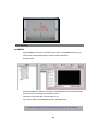
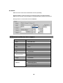
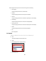
1
IDTECK 5F, Ace Techno Tower B/D 684-1 Deungchon-Dong Gang-Gu Seoul, Korea Phone : 82 2 2659 0055 Fax : 82 2 2659 0086 Web : www.idteck.com STARWATCH VIEW PRO SOFTWARE USER MANUAL STARWATCH VIEW PRO User Manual STARWATCH VIEW PRO MAIN FUNCTIONS ..................................................................................................................................... 1 STARWATCH VIEW PRO PROGRAM SETUP REQUIREMENTS .................................................................................................. 4 OPERATING SYSTEM .....................................................................................................................................................................4 USING HYPER-THREADING TECHNOLOGY PROBLEM.....................................................................................................................4 MINIMUM SERVER SPECIFICATION .................................................................................................................................................4 RECOMMENDED SERVER SPECIFICATION ......................................................................................................................................4 OPTIMAL SERVER SPECIFICATION .................................................................................................................................................5 STARWATCH VIEW PRO PROGRAM SETUP...................................................................................................................................... 6 OPERATING SYSTEM)....................................................................................................................................................................6 MICROSOFT OFFICE 2000 PROGRAM ............................................................................................................................................6 INSTALLATION ...............................................................................................................................................................................7 INSTALLING WEBEYE 2.0 PROGRAM ( FOR WEBGATE WEBEYE SERIES)...................................................................................9 QUICK INITIALIZE .........................................................................................................................................................................11 MAIN WINDOW............................................................................................................................................................................................ 14 FUNCTION LIST ........................................................................................................................................................................................... 15 TOOLBAR ....................................................................................................................................................................................15 PROGRAM FOLDER ................................................................................................................................................................................... 16 DATABASE STRUCTURE .......................................................................................................................................................................... 16 RUN ................................................................................................................................................................................................................... 17 PROGRAM CONFIGURATION ................................................................................................................................................................ 17 CONFIGURATION .........................................................................................................................................................................17 UDP SEVER BROADCAST ...........................................................................................................................................................17 IP CHANGE ( FOR WEBGATE VIDEO SERVERS).........................................................................................................................18 CHANGING IP ADDRESS BY WEBEYE2.0 CONFIGSTATION (FOR WEBGATE VIDEO SERVERS) ................................................19 IP ADDRESS CHANGE (FOR FLEXWATCH VIDEO SERVERS) ......................................................................................................20 CAMERA DEFINITION ...................................................................................................................................................................24 DUAL MONITOR USE ...................................................................................................................................................................33 CAMERA CHANNEL LOCATION .....................................................................................................................................................34 MOVING CHANNEL TO THE OTHER MONITOR.................................................................................................................................35 AUTOMATIC DELETE ...................................................................................................................................................................36 MAIN SCREEN FUNCTION EXPLANATION....................................................................................................................................... 38 PARTITION SCREEN MODE DEFINITION ........................................................................................................................................38 CONTINUOUS WATCH MODE .......................................................................................................................................................39 NEXT VIEW ..................................................................................................................................................................................40 REFRESH ....................................................................................................................................................................................41 LANGUAGE..................................................................................................................................................................................41 EVENT LOG .................................................................................................................................................................................41 RECORDED SCREEN PLAYER FUNCTION DEFINITION.............................................................................................................. 45 PLAY BUTTON .............................................................................................................................................................................45 PLAY SPEED ADJUSTMENT .........................................................................................................................................................46 2 CONTINUOUS PLAY .....................................................................................................................................................................46 PLAY LIST SELECT ......................................................................................................................................................................46 IMAGE EXPORT ...........................................................................................................................................................................47 MOTION PICTURE EXPORT ..........................................................................................................................................................47 CONNECTING & SETTING SERIAL PORT.......................................................................................................................................... 49 B106 CONNECTING.....................................................................................................................................................................49 B101 CONNECTING.....................................................................................................................................................................50 SETTING SERIAL PORT ............................................................................................................................................................................ 51 WEBEYE2.0 CONFIGSTATION LOGIN...........................................................................................................................................51 SETTING DEVICE .........................................................................................................................................................................51 PTZ DEVICE SETTING............................................................................................................................................................................... 53 SET PTZ PORT(FOR WEBGATE WEBEYE SERIES) ..................................................................................................................53 SET PTZ CHANNEL .....................................................................................................................................................................54 PTZ OPERATION......................................................................................................................................................................................... 54 PTZ OPERATION .........................................................................................................................................................................54 PTZ SETTING ............................................................................................................................................................................................... 55 SET PRESET.............................................................................................................................................................................55 SET GROUP ..............................................................................................................................................................................56 PTZ PROTOCOL AND DEVICE LIST TO SUPPORT ......................................................................................................................... 56 USING MULTI LANGUAGE SETUP PROGRAM ................................................................................................................................ 57 SCREEN LAYOUT .........................................................................................................................................................................57 SET LANGUAGE ...........................................................................................................................................................................58 SET MENU...................................................................................................................................................................................59 SET FORM ...................................................................................................................................................................................61 SET MESSAGE.............................................................................................................................................................................62 SET DROP DOWN LIST ................................................................................................................................................................63 SET ETC......................................................................................................................................................................................64 DEVICE SPECIFICATION.......................................................................................................................................................................... 65 NETWORK VIDEO SERVER(WP101 / WP106).............................................................................................................................65 NETWORK VIDEO SERVER(FLEXWATCH 3440) .........................................................................................................................67 DVR(WEBGATE) ........................................................................................................................................................................68 DVR(WIN4NET) ........................................................................................................................................................................70 COMPARISON TABLE (VIEW PRO WITH EACH DEVICE) .................................................................................................................71 3 Chapter Installation Environment 1 STARWATCH VIEW PRO Introduction This chapter explains STARWATCH VIEW PRO’s main functions and installation environment.. STARWATCH VIEW PRO MAIN FUNCTIONS STARWATCH VIEW PRO Program could be linked to our existing access control programs, STARWATCH ITDC PRO/STARWATCH DUAL PRO, and provide visual power of Digital watching and recording. STARWATCH VIEW PRO is perfectly compatible with our Access Control System software and can control various digital surveillance support and additional function which will increase your ability to secure the willing perimeter. • Recommended Device Adoption STARWATCH VIEW PRO supports integrating various image observational device. Provider Type Model Network Video Server WebEye B101(1CH), WebEye B106(6CH) eDVR DS1600 Series(16CH), WebGate www.wegbateinc.com DVR eDVR DS800(8CH), eDVR DS412(4CH+IPCam 12CH), i-Rec B104(4CH) Seyeon Tech www.flexwatch.com Network Video Server FW-3440(4CH), FW-3110(1CH) Netsafe-DVR 1000Series Win4NET www.Win4NET.com DVR Netsafe-DVR 2000Series Netsafe-DVR 3000Series Netsafe-DVR 7000Series * Please refer to each device manufacture website according to detail device specification. STARWATCH VIEW PRO is continuously going to support various kinds of DVR. • Dual Monitor Support One monitor can display 16 channels at a time and 32 channels can be sensed at a time when using dual monitor-support VGA card. • Multi Screen Support The software supports multi screen function (1, 4, 10, 13, 16) which user can choose the number of screens to display according to his/her convenience after considering the number of cameras and importance of the viewing sites. We recommend the user to put important viewing site at the convenient location among the partitions. • Continuous surveillance option It supports continuous surveillance on (1, 4, 10, 13, 16) channels. Use this option on your own convenience. • PreAlarm function STARWATCH VIEW PRO the recording function for passed view in buffer from minimum 5Sec to maximum 30Sec. When card event alarm or something unusual occurs, recording or viewing initiates according to the time schedule user arranged previously.. • Event log and Map Function Support When an event alarm occurs, according to preset configuration, designated recording and viewing function will initiate and show the surveillance site together with the location of the camera on the perimeter’s blue print. Recorded viewing will be marked on the event log and it can be play-back or connected to the map(blue print) to see the event-occurred-location • Various Record play-back function Continuous play-back, forward and reward play, various replay-speed-set function. • Exporting Image and avi file function Recorded screen can export through BMP and AVI files. Created file through export can be played through image viewer or avi player. • Camera device Search function It supports to search camera device which is connected through local network. Administrator doesn’t have to remember which camera is connected to which IP. This function can save your time. 2 • Multi Language Support Multi Language support basically two languages (Korean, English). Additional 5 languages can be supported through inputting language-data by user. Unified user interface User interface of View Pro is unified with iTDC Pro, and Dual Pro (icon images). If you are familiar with our access control software already, it would be very easy to familiarize. 3 STARWATCH VIEW PRO Program Setup Requirements Operating System STARWATCH VIEW PRO is 32-bit Windows compatible program. This program can be operated in Windows 2000 Professional, Server Edition and upgrade version, Windows XP Home and Professional Edition. STARWATCH VIEW PRO Program doesn’t support Windows 98, ME, NT 4.0. STARWATCH VIEW PRO Program is recommended to install in Windows 2000 Professional or Windows XP Professional. This OS is powerful and stabilized. It will enable STARWATCH VIEW PRO work steady, and safely. Using Hyper-Threading Technology Problem Windows2000 operating system does not support Hyper-Threading Technology (HTT). If you want to use HTT, Confirm OS support HTT. Minimum Server Specification Minimum configuration is suitable to the less than 6channel system. Enlargement of memory can improve system function. Sufficient space of HDD makes it possible to record longer time. 9 CPU : Pentium III-700 or higher 9 MEMORY : 256 megabyte or higher 9 HDD : 2G or higher(More than 20G to record screen) 9 NETWORK : 1 Ethernet Card 9 OS : Windows 2000 Professional or Windows XP Home Recommended Server Specification Recommend Configuration is suitable to 6~16 channels system. We recommend PC with f below mentioned specifications. Enlargement of Memory and enough space of HDD recommended. 9 CPU : Pentium 4 1.5G or higher 9 MEMORY : 256 megabyte or higher 9 HDD : 4G or higher(more than 40G to record screen) 9 NETWORK : 1 Ethernet Card 4 9 OS : Microsoft Windows 2000 Professional or Microsoft Windows XP Professional Optimal Server Specification Performance Configuration is suitable to 16~32 channels middle to large sized system. We recommend to use Sever Computer with below mentioned specifications. Enlargement of Memory and enough space of HDD recommended. 9 CPU : Pentium 4 -2G or more / recommend dual CPU 9 MEMORY : 512 megabyte or more 9 HDD : 8G or more( more than 80G to record screen) 9 NETWORK : 1 Ethernet Card 9 OS : Microsoft Windows 2000 Server or Microsoft Windows XP Professional 5 Chapter 2 Installation STARWATCH VIEW PRO Program Installation This chapter leads you to install STARWATCH VIEW PRO Program. STARWATCH VIEW PRO Program Setup Operating System) The following is the STARWATCH VIEW PRO installation OS. Microsoft Windows 2000 Professional Edition (SP4 or more) Microsoft Windows 2000 Server Edition (SP4 or more) Microsoft Windows XP Home Edition (SP1 or more) Microsoft Windows XP Professional Edition (SP1 or more) Also, it is not mandatory, but we recommend installing Internet Explorer 6. If you do not have this browser, you can download at Microsoft Web Site. http://www.microsoft.com/downloads/search.aspx?displaylang=en Microsoft Office 2000 Program STARWATCH VIEW PRO uses the Microsoft Access 2000 database within the Microsoft Office 2000 application. Microsoft Office 2000 program is not mandatory, but it’s convenient for database and user operation (Installing Microsoft Office XP works the same). We strongly advise to install it if you already have the program. 6 Installation Find the setup file in ‘/install files’ folder in the software CD and double click it to initialize its installation. 1) As the following window shows on the screen, click “Next” in order to star the installation process 2) Click “Next” to install it in the default directory. In order to change its install directory, click” Browse” and choose a folder to install the STARWATCH VIEW PRO software . 7 3) Click “Install” to start its process. 4) During the process, you will see the installing status. Please wait. 5) If completed, it shows as below. Click “Finish” to finish it. 8 Installing WebEye 2.0 Program ( For WEBGATE WebEye Series) 1) Execute WebEye 2.x.x.x Installer.exe in \Utility\WEBGATE folder in Setup CD. 2) Press the “I Agree” button. 3) Select a file to install, and press the “Next” button. 9 4) Select a folder to install and press the “Install” button. 5) Complete to install with pressing the “Close” button. 10 Quick Initialize This context leads you to start STARWATCH VIEW PRO Quick Initialize. This is useful when executing minimal function of software before reading the manual. If you want specific manual, read Program Environmental Setup 1) Click [View] -> View Surveillance menu in Access Control Program. 2) Click Environmental Setup button. 3) Select Monitor-1 in the tree view menu on the left side. 4) Click the check box of “Use Monitor” and select the video device type that is connected to the system. 11 5) If the device is DVR, have to enter IP address, Port No, Login ID and Password in each fields. 6) Click UDP-Search button. 6) Select one of the searched lists and click Apply button. 7) Insert code and name. Code and name can be inserted as user’s will and code is consisted of English and number 8) Insert IP Address. If UDP search is used, choose selected IP Address and click Apply button to insert IP Address and port automatically. 9) Insert Login ID and Password (WEBGATE initial value: admin, FlexWATCH initial value : root, Win4Net DVR : not use) 10) Click save button and after that click close button to close setup. 11) You can verify screen played in main screen. . 12 Quick Initialize is not a desirable setup to run software. To use it right, we recommend you to read the manual thoroughly. 13 Chapter 3 Program Structure STARWATCH VIEW PRO Program Structure This chapter explains the structure of STARWATCH VIEW PRO. It explains Main screen structure, Toolbar, Directory and Database file. Main Window STARWATCH VIEW PRO Main Window consists of 3 parts Top section consists of menu of tool bar. The middle part shows screen display. Bottom section shows status. User can initiate function quickly and efficiently by using the main screen. 2. Main View It provides real time video images of cameras connected to the system 1. Toolbar It provides various options of video display and short cuts of basic menu. 5. Map Display I t shows the location of current event with a map set by user for each camera 6.Event Log Map It shows the location of log event with a map chosen in the event log display 3. Event Log display / PTZ control It displays access / alarm events with video image or PTZ control tool 4. Caption setting It provides various options of caption display on the video screen 14 7. Sequential View It displays video image of camera channels in turns, which does not show in main view window Function List Toolbar Icons in Toolbar are most frequently used program functions. The functions for each Icons are as listed below. Toolbar Icons Viewing 1 Partition Watching 1 channel with high-resolution. Viewing 4 Partition Watching 4 channels with mid-resolution. Viewing 10 Partition Watching 2 channels with mid-resolution and 8 channel with low resolution. Viewing 13 Partition Watching 1 channel with mid-resolution and 12 channels with low resolution. Viewing 16 Partition Watching 16 channels with low resolution. Continuous Watching Mode Start continuous watching mode or Exit. 1Partition Continuous Watching Setup continuous watching mode in 1 Partition screen. 4Partition Continuous Watching Setup continuous watching mode in 4 Partition screen. Next Partition Continuous Watching Next Continuous Watching Screen Setup Convert partition screen to next channel. Convert continuous watching screen to next channel. Setup camera device information. Reconnect Try to reconnect setup-channel. Language Language Setup Exit Exit Program 15 Program Folder This explains folder which STARWATCH VIEW PRO is installed. STARWATCH VIEW PRO Program is installed in C:\Program Files\STARWATCH\STARWATCH VIEW PRO folder The folder which is installed program can be changed by user. Database Structure STARWATCH VIEW PRO Program consists of 2 database file. All database files are created as Microsoft Access 97 files. But to read or modify data it can be opened in Access 2000. Do not convert the file to other database version (Access 2000, Access XP) Database files consist as below. ViewPro.mdb Main database file of STARWATCH VIEW PRO program which preserves device information, event setup information and event log. STAR-LANGUAGE.mdb Multi language database file in STARWATCH VIEW PRO which preserves all the literal information placed on the screen. 16 Chapter Initial Setup 4 STARWATCH VIEW PRO Initial Setup This chapter explains installation items setup, after installing STARWATCH VIEW PRO. Run To execute program click View Camera menu in STARWATCH ITDC PRO or DUAL PRO’s [View]-[Video Surveillance] menu. Program Configuration Configuration To setup configuration click toolbar or setting button after STARWATCH VIEW PRO main screen displayed. UDP Sever Broadcast Camera device (camera server, DVR) which is connected to local network can be searched automatically by this function. This makes it easier to verify device information, change of IP Address and setup camera setting. UDP Server Broadcast 1) Select video device type to search it in the network. 17 2) Click UDP Search button. Searching Result 1) The result of UDP Broadcast is as below. 2) When clicking searched device in list you can see detail information of device. [Reference]UDP Broadcast is broadcasting local network. When device is connected in remote area broadcasting doesn’t work. IP Change ( For WEBGATE video servers) When device is connected for the first time, to use device you should setup IP Address. IP Change 1) Search device using UDP Broadcast. 2) Click device which you want to set IP Address in selected device. 3) Click IP Change button. 18 Input Changed Information. 1) Insert IP Address you want to set. If you don’t know the address, contact administrator. 2) Insert administrator password. “ADMIN” is default value. 3) Click Save Button. 3) After verifying Completed message, click Close button. Changing IP Address by WebEye2.0 ConfigStation (For WEBGATE video servers) After connecting WebEye to Network, its IP address should be changed according to each Network environment to access WebEye normally. 1) Run WebEye II ConfigStation in PC. 2) All WebEyes, which are connected to local Network, are displayed in “Local Area Servers” 3) Select WebEye. 4) Change its IP address suitably. 5) Enter password. 6) Press the “Change IP” button. 19 If IP address is changed, WebEye shows new IP address in “Local Area Servers”. IP Address Change (For FlexWATCH video servers) When device is connected for the first time, to use device you should setup IP Address. IP Change 1) Install Utility\FlexWATCH\FlexWATCH Explorer_1.xx_xxx.exe on CD. 2) Run FlexWATCH Explorer on show desktop. 3) Running window is as shown below. Menu Description 20 A. Search Show models searching FlexWATCH which is installed on same network band. B. Clear Delete all list which have been searched. C. IP Setup Set up network information. D. Recommend IP Setup FlexWATCH sets up network information automatically. * If no use devices have temporarily, duplicate IP may occur. / * If no use devices have temporarily, IP may collide. E. Connect Link homepage of corresponding device. * PC band should be same with FlexWATCH IP band. F. Search List Show searched list. G. Total Show total devices which are searched. H. Found Show total devices which are searched normally. * After searching, total devices which are searched normally when researching. I. Timeout Show total devices which don’t respond on stop. * After searching, total devices which aren’t searched normally when researching. 1) Click “Search” icon. 21 2) Click right button of mouse for IP Setup among list which have been searched. Menu Description A. Connect FlexWATCH Link homepage of corresponding device. B. IP Setup Set up network of corresponding device. 3) Click IP Setup. 4) Enter settings for network setup. 22 Menu Description A. IP Type Select “Static”. B. Server Name Set up “Server Name” that “FlexWATCH”. C. Network Network Settings Information (Contact network manager and then set up it.) IP Address Enter “IP Address”. NetMask Divide IP band. Default Gateway Enter “Default Gateway”. DNS1, DNS2 Enter address of “Domain Name Server”. D. HTTP Port Use default 80 (FlexWATCH) of HTTP Port. E. Authentication Key As Root password, default value is “Root”. F. Save Configuration Option Save network settings. Save Configuration Save on the flash memory about all settings. Not Saving Don’t save all settings. * In case of not a saving, if device is off or reboot, current settings may disappear. 5) After finishing network setup, click “Set” icon. 6) If changed IP researches rebooting a device, network setup will be completed. 23 Camera Definition Setup screen is to be shown as below Shortcut key Shortcut key which is used in setup screen is as below. Function Shortcut key Add CTRL + A Modify CTRL + M Delete CTRL + D Save CTRL + S Close CTRL + X, Alt+ F4 Treeview CTRL + T Monitor Select Select Monitor which camera will be added. Only one monitor is shown when loading program first. After clicking monitor click Add button. 24 Basic Info 1) Click Basic Info tab. 2) Insert basic info of camera device orderly. 3) IP Address can be registered by using broadcasting UDP function. 1. Click device which you want to setup in selected list. 2. Click Apply button. 3. In the IP address field it shows the IP selected in UDP search. 25 Basic Information List Code This is a unique code for each channel. You can define by Inserting English alphabet or 4-digit number briefly. The codes should not overlap between each other. Name This is a brief name which explains channel for your convenience. IP Address Port Number Login ID Password This is IP number of camera device. If you don’t know IP number of connected device, use UDP Broadcasting. This is connected Port number of camera device. Default number is 80. Login ID’s default value is ‘admin’. Login Password. Channel Number Choose the channel number you wish to surveil. Number of channels can be vary due to the connected device. Refer to H/W manual to check supported channel number. Activate Decide whether to use a channel or not. If you want to use the channel check, and if you don’t, just leave setting value and don’t check. Motion Detect Rec. Voice Port Video Mode Use Motion detect recording [FlexWatch Only]This is connected Port number of Voice device. Default number is 32001 Choose your preference of screen mode. Selectable between DirectX and The basic graphic. [Reference 1] PTZ Board ID [FlexWatch Only]This is connected Bard ID of PTZ Device. Not use : blank, Use : 0 ~ 255 Alarm Duration Choose how long the alarm will beep when an alarming situation occurs. Alarm Sustain Time is the time of screen recording. Pre-Recording Time(Sec) Define the time to start recording screen – how many seconds before alarm event occur. [Reference 3] (Frame / Sec) Frame per Second in normal status. [Reference 2] Alarm Frame Rate FPS during sustainable Alarm time. Frame Rate Record-Path The Path screen file will be saved. [Reference 4] [Reference 1]Screen Mode - If using DirectX, VGA can card handle screen process so CPU can work easily. But if VGA doesn’t support DirectX or DirectX version is low, the screen couldn’t be displayed. In this case, install latest DirectX version or use default graphic. 26 [Reference2]FPS –The higher Fps the softer screen image shows. But if FPS gets higher, CPU usage statistics climbs which is not recommendable. [Reference3]Pre-Recording works using PreAlarm which is saved in device buffer. Buffer memory in device contain minimum 5~30 Sec PreAlarm. And if alarm occurs, watching and recording starts using screen data saved in buffer. The screen data transmitted will display fast movement until the present time. [Reference4] Record Path – Recorded screen is saved as re3 file type in HDD. Enough space of HDD is required. If physically divided HDD is, this could upgrade program function. Map Info 1) Click ‘Open’ button. 2) If Open window screen shows, choose map image file of chosen channel and click Open button. 27 4) When the Map image is displayed Drag&Drop camera where it’s actually installed. Reader Event Info 1) Click Reader Event Info tab. 28 2) Double-click Reader from left List. 3) 2Choose Event Type. 4) Choose Event Action. There are 5 situation configurations. 0 Ignorance: Ignores event. 1 Watch: Show passed screen to watch event situation. 2 Record : Record Event 3 Capture Image 5) Continue 2) and 4) and register all the card event setup which you want to handle. Card Event Items Port Number The Port number is to communicate with ACS device which is connected to camera. Board Number Board Number of ACS device which is connected to camera. Reader Number Reader Number which is related to camera.. ValidID InValidID Granted card event occurs. Disapproval card event occurs. InValidTimeSchedule Disapproval card event occurs during disapproval time. AntiPassbackInErr Occurs when someone try to violate AntiPassBack(IN) AntipassbackOutErr PasswordErr AccessDoorErr Occurs when someone try to violate AntiPassBack(OUT) False Password. False ID. FingerErr Undefined Fingerprint. DuressErr Someone’s trying to force a personnel to let him in. Forced Door Open Door Opened Arm When someone try to open the door without authorization. When someone try to open the door beyond the setting time.. When alarm is set.. 29 Disarm Handicap When alarm is released.. On Handicap Person Mode 2Men Guard When 2Men Administrator ID is authenticated.. 2Men Visitor When 2Men Visitor ID is authenticated.. 2Men TimeOut Excessive 2Men Authentication Time [Reference 1]Screen Mode - If using DirectX, VGA can card handle screen process so CPU can work easily. But if VGA doesn’t support DirectX or DirectX version is low, the screen couldn’t be displayed. In this case install latest DirectX version or use default graphic 30 Apply Default Reader Select a reader for each camera in relation of video recording/monitoring of the reader site. The inter-connection among readers and cameras is to be applied for video pupup display and recording in the main software of access control. 1) Select one of the readers on the left list and click on “Apply Default Reader” . Input Event Info 1) Double-click Event from left list. 2) Input contents. You can input name which is compatible with input event. Ex) Fire Alarm, Exit button. 3) Choose a way to react when each input event occurs. You have 3 choices as below. 0 none: Ignore occurred event. 31 1 Monitor: Display passed screen to watch event occurred. 2 Rec: Record event occurred situation. 3 Capture Image: Capture BMP image. 4) Continue 1) and 3) and register all the input event setup which you want to handle. [Reference] Camera Device can be used as combination of a reader or a controller. So use the Card event setup or the input event setup properly according to the installed reader location, each sensor or button locations, and the camera locations. 32 Save, Modify, Delete of registered information 1) When configuring the camera devise is done, click save button. 2) If you want to modify camera information, click the camera which you want to modify in tree view and modify. After modifying is completed click save button. 3) If you want to delete camera information, click the camera which you want to delete in tree view and click delete button. Dual Monitor Use When your VGA card supports dual monitor mode, each one of your monitor can support 16 channels(maximum 32 channels) to display. Multi-Monitor Setup 1) In order to use dual monitor, click on the check box of “Use Monitor” on each monitor (Monitor-1, Monitor-2). 33 Multi-Monitor Use Screen. 1) When using Dual Monitor View Pro, 2 main windows appear. 2) You can simply locate the VIEW PRO window at the convenient place as you wish. 3) When exiting the program, each window locations, partition screen option, and the continuous watch option are saved automatically. 4) When you restart the program, the display will be as saved from your latest exit. Camera channel location User can move the location of the camera channel as preferred. Moving channel up and down. 1) Enlarge tree view by clicking monitor image. 2) Click channel which you want to move. 3) Move to the place you want by using up and down button on the right. 34 Location of channels is as same as location of VIEW PRO Main screen displays. You can move channels to the place as you prefer. Moving channel to the other monitor. You can move setup channel to the other monitor by dragging and dropping of mouse. Moving channel to the other monitor 1) Enlarge tree view by clicking monitor which has channel you want to move. 2) Click camera you want to move by using the right button of the mouse. 3) Move the mouse to the place where you want to put the camera by clicking. 35 4) Release your mouse button.. Automatic Delete Automatic Delete supports to delete expired event log and video recording file automatically. Automatic Delete Use 1) Click [Tools] -> Automatic Delete menu in Definition Camera Program. 2) If you want to use automatic delete Check Log delete than is old more than next. 36 3) Select a period 4) Click save button and after that click close button to close setup. 37 5 Chapter Main Screen Function This chapter explains the STARWATCH VIEW PRO Main Screen Function in detail. Main Screen Function Explanation STARWATCH VIEW PRO supports various functions to control ACS effectively. Partition Screen Mode Definition Partition Screen Mode Definition consists of 1 partition, 4 partitions, 10 partitions, 13 partitions and 16 partitions. According to the count of channels to watch and importance of location, you can select appropriate partition modes. Partition Mode Kinds Language 1 Partition 4 Partitions 10 Partitions 38 13 Partitions 16 Partitions Partition Mode Select You can select Partition Mode using Toolbar. Continuous Watch Mode Continuous Watch Mode is the function to show not displayed channel every set-time . Location of Continuous Watch Mode function button Continuous Watch Mode can be set by using toolbar’s function button or right-bottom side function. 39 Continuous Watch Mode Set Continuous Watch Mode can be set or set off by clicking Toolbar button or clicking continuous watch use check button. When Continuous Watch Mode is set, basically it works in Sequence View Area. Continuous Watch Mode Set in Main View Area. 1) As full view mode to change screen every set time, you can set continuous watch mode. Full view continuous watch mode works only when screen is 1 or 4 partition mode. Set Sequence Monitor Converting period in Sequence Mode. Unit is milliseconds and can be set from 1000ms ~ 6000ms. Next View Show Current partition mode or sequence monitor next view. Next View (Main View Area) : Show next view of partition Viewing Area. For example, Every time clicking next view (Main View Area) in 4 screen partition is show as 1~4 Monitor -> 5~8 Monitor -> 9~12 Monitor -> 13~16 Monitor -> 1~4 Monitor In 10 Monitor Partition every time clicking button shown as 1~10 Monitor -> 11~16 Monitor -> 1~10 Monitor Next View (Sequence View Area) : Show next monitor in Sequence View Area. Every time clicking next view monitor changes to next view. 40 Continuous Watch function or Next View function doesn’t work when all the channels are shown current monitor partition. Refresh Because of temporary network problem or device problem camera connection failed then click ‘Refresh’ to reconnect all the set channels. Language Supporting of multi-language make it possible change basic language used in program. Event Log When event occurred according to setup record starts. The recorded event is written in event log, makes it easier to search and play recorded screens. Event Log Event log shows information like below. Event Log Items Channel Time Show channel code which event recorded. This is user inserted value in camera registration setup. This is the time event has occurred. 41 Name Show channel name. This is user inserted value in camera registration setup. Event Event type. Definition Record File Path Definition of Event. Card Event shows number, input event shows explanation. Shows whether recorded or not. The path file is recorded. Event Log Delete After verifying recorded screen if there is no problem, delete useless event logs. This will make your HDD space more available. 1) Delete 1 line Click the line you want to delete and click the delete button. 2) Delete multiples lines Drag lines you want to delete and click delete button. 42 Recorded Screen Play Choose event log and click play button then player load and record. 1) Play 1 line Click the line you want to play and click delete button. 2) Play multiple lines Drag lines you want to play and click play button. Map View When event occurred or clicked event log then shows map of event-occurred location. Map shows location of installed camera. 43 1) Event Map Event Map is shown when event occurred right away. 2) Event Log Map Event Log Map shows the location of event-occurred location when clicking event log. 44 Recorded Screen Play Function Chapter 6 This chapter explains the STARWATCH VIEW PRO recorded Screen Play Function. Recorded Screen Player Function Definition Our player supports various functions to make it easier to play recorded screens comfortably. Play Button For easy and comfortable use, player provide icon button which is related to play. Icons related to Play First Move playing file to the start location. Back Move playing file to the backward location. Backward Play Plays backward. 45 Pause Play Forward Stop playing for a moment. Playing forward. Move to the forward of playing file. Last Move playing file to the last location. Open Open playing file. File Open window loads. Play Speed Adjustment Play speed can be adjusted. 단계 Slow(0.5x) Normal(1x) Fast(1.5x) Faster(2x) Continuous Play When playing various recorded screens, player supports continuous play function. If you don’t want to use Continuous Play uncheck Serial View. Play List Select In couple of play items in list click the screen you want to play. The player plays the selected screen. 46 Image Export Player supports exporting image by BMP file type when file is playing. 1) Input image save path and file name. Basic setup is same path and same file name with recorded file. Extension is saved to BMP automatically. 2) Click image save button to the location you want to send image. It is possible to pause play to export an accurate image. Motion Picture Export It is possible to export playing screens as AVI file type. 1) Input AVI save path and file name. Basic setup is same path and same file name with recorded file. Extension is saved BMP automatically 2) Input fps. Default value is 30 fps. If Fps is low, screen interference is shown but file size is small and if high, screen interference is not shown but file size get larger. 3) Click Export button. 4) If Video Compression window loads, select a Compressor. 47 5) According to Compression type there can be additional input items. Input values according to type. 6) After all setup has been completed, click export start. Video Compression type can be different according to codec which user has installed. When error occurs during exporting is because of this. In this case use another codec. The problem because of codec is not in our technical support area. 48 7 Chapter Setting Serial Port This chapter explains the WebEye Serial Communication Setting.( For WEBGATE WebEye Series) Connecting & Setting Serial Port B106 Connecting Connection RS232 When connecting to GND, RX, TX, insert cables to 2~4pins followings. Connecting RS422 When connecting to insert 6~9pins(R+,R-,T+,T-) Connecting RS485 When connecting to insert 6~7pins(R+,R-) 49 B101 Connecting Connecting RS232 When connecting to GND, RX, TX, insert cables to followings. RS422Connection When connecting to insert R+,R-,T+,TRS485 Connection When connecting to insert R+,R- 50 Setting Serial Port WebEye2.0 ConfigStation Login 7) Run WebEye II ConfigStation in PC. 8) All WebEye devices which are connected to local Network, are displayed in “Local Area Servers” 9) Select WebEye to access. 10) Enter password. Press the “Login” Button. Setting Device After connecting device to serial port, set a value according to device. 51 1) Log in WebEye and click the “Device” tab. 2) Reference a next table and select port matched with device. RS-232 RS-422 B101 COM1 COM2 B106 COM1 COM3 3) Set the related serial port to “[SERIAL_TP]”. 52 8 Chapter PTZ Function This chapter explains the PTZ function ( For WEBGATE WebEye Series) PTZ Device Setting Set PTZ Port(for WEBGATE WebEye Series) To operate PTZ correctly, set a protocol suitable for PTZ device, controlled port by each channel, and PTZ device address. Select Device tab. See figure below. To set the PTZ protocol, select a protocol of PTZ Device. Input Interface, Parity, Stop, Data and Baud rate correctly. 53 Set PTZ Channel Input PTZ Port and Device Address in Channel tab. PTZ Operation PTZ Operation Click right button of mouse at ViewPro Monitoring screen and select PTZ. See figure below. If PTZ of Popup window is checked, shows a cross dotted line which is the center coordinates. And then, you can control PTZ. If PTZ isn’t operated although show a cross dotted line, it means PTZ setting is not correct. Occurs PAN/TILT operation during clicking left button of mouse Up and down, right and left from the center of a cross dotted line like fig below. If the position of mouse becomes more distant, PAN/TITLT moves rapidly from the origin. You can Control FOCUS, Zoom operation to locate mouse pointer on both edge sides of a screen. To move the saved home position in PTZ device, click the center of a cross dotted line. It depends on what the device support or not. 54 PTZ Setting Set PRESET Support PRESET function by some kinds of PTZ device. Using PRESET functions, you can return the saved position again as save the position information. See figure below. Check the PRESET to register in Check List on the left side and then fit Camera direction, Zoom and Focus to set using PTZ Operation function. Input Name in the Name field. Click Set button to set. If you want to delete a saved PRESET position, click Clear button. The count of PRESET to save can be different by device and used protocol. 55 Set GROUP GROUP function is that rotate saved PRESET screens periodically. Register PRESET to rotate to Seq list by turns like figure below. And select applicable GROUP on the left side. Then the position is moved periodically by saved turns in Seq List. Moving Period is a movement time interval of RRESET. PTZ Protocol and Device List to support Provider Protocol or Model Pelco Pelco D(M) / P(M) Philips Philips(M) Sensormatic Open P(M) Sony EVI-D VT VPT-4x(M) Canon VC-C4 Lilin Past Dome(M) SPD2500 Samsung(Techwin) SRX-100B Support DRX-500(->SRX-100B) Sungjin SJ-100 Series Honeywell ScanDome2 Patch LPT-A100L(LG) PTZ List Newborn(M)(Japan) CIT7300(MITSUBISHI) PTC200C(ELMO) 56 9 Chapter Multi Language Setup VIEW PRO Program Multi Language Setup This chapter explains VIEW PRO Program Multi Language Setup instruction. Using Multi Language Setup Program The VIEW PRO Multi Language Setup Program is used to configure VIEW PRO Program multi language support. It is for the user to configure the language preference, form, menu, drop down list, and message functions to input and modify data. Screen Layout Initiating the VIEW PRO Multi Language Setup Program will display the following screen. Main window consist of left hand side menu and right hand side function types. Menu Function setting menu of multilingual setting program of DUAL PRO™ Program Area The screen of function selected in menu is shown in program practice area. The functions users want is executed through this area. Menu Layout 57 Multi Language Setup Program menu and its function types are the following. 9 Set Language Configure language preference by character style. 9 Set Menu Configure language preference for the top part menu display. 9 Set Form Configure language preference for characters in input/output on screen display. 9 Set Message Configure language preference for characters in message display. 9 Set Drop Down List Configure language preference for characters in all Drop Down Combo display. 9 Set Etc Configure language preference for the remaining categories. 9 Exit Save configuration. Set Language Language configuration is the setup of fonts for each language type. Start Select Set Language from left hand side menu. Setup 1) Select language used in language category. 2) Select Screen Font 58 3) Select Save button to save data. Set Menu Setup language preference for top part of menu. Start Select Set Menu from left hand side menu. Setup Multi Language input screen display the following, and the Korean and English languages are shown. Input the user’s language with English as the standard base. For example, if using User Define 1 language, input the language preference by looking at the English Row. Input the user’s language with English as the standard base. The above input will display the following screen. If all inputs are completed, select 59 Close button to finish. Inputs are saved automatically without a separate save function. All user needs to do is input data. As shown above, input the menu caption then select User Language 1 in VIEW PRO program, and it will display the following screen below. 60 Set Form Setup of characters displayed in all input/output screen display. Start Select Set Form from left hand side menu. Setup Multi Language input screen display the following, and the Korean and English language can be seen. Input the user’s language with English as the standard base. For example, if using User Define 1 language, input the language preference by looking at the English Row. Input the user’s language with English as the standard base. As shown above, input the form caption then select User Language 1 in VIEW PRO program and it will display the following screen below. 61 Set Message Setup of language message display in VIEW PRO program. Start Select Set Message from left hand side menu. Setup Multi Language input screen display the following, and the Korean and English language can be seen. Input the user’s language with English as the standard base. For example, if using User Define 1 language, input the language preference by looking at the English Row. Input the user’s language with English as the standard base. Message box display of Language: 1.Korean setup. Message box display of Language: User Language1 setup. 62 Set Drop Down List Configure language preference for input/output in all Drop Down Combo display. Start Select Set Drop Down List from left hand side menu. Setup Multi Language input screen display the following, and the Korean and English language can be seen. Input the user’s language with English as the standard base. For example, if using User Define 1 language, input the language preference by looking at the English Row. Input the user’s language with English as the standard base. DropDownList display of Language: 1.Korean setup. DropDownList display of Language: User Language1 setup. 63 Set Etc Setup of language for default value input items. Start Select Set Etc from left hand side menu. Setup Initiating the Multi Language input screen will display the following. Input language preference in CAPTION column using REF CAPTION as base. A separate column for Etc is not available. These values cannot be setup due to fixed value setup in database. However, using REF CAPTION as base to modify the CAPTION column value, the fixed value of data language can be modified. REF CAPTION cannot be modified. This value is for reference to language modification. The actual character displayed in program is the CAPTION column value. Input the user’s language with REF CAPTION as the standard base. The modified details in VIEW PRO Multi Language Setup Program are applied immediately without rebooting the VIEW PRO program. However, the current running screen needs to be closed and reopened to display the modified language. 64 10 Chapter Device Specification Device Specification Network Video Server(WP101 / WP106) WP101 / WP106 Key Features -Monitoring through existing CCTV camera over Internet -4.5 MB Flash Memory for Homepage Customization -Max. 100 Simultaneous Users Support -Max. 64 Points Preset Control (Group and Swing Mode Support) -WP101 only -RS232 and RS485/RS422 Port Support for PTG Control -Audio Support (Audio Support Kit is Optional) -Embedded Linux OS for Excellent Stability and Less Downtime -Wavelet Compression (30-300% greater efficiency than JPEG) for Higher Refresh Rate and Crisper Images -WP106 : 6 Channel Support / 6 External Sensors Support WP101 : 1 Channel Support / 4 External Sensors Support -S/W Motion Detection (each channel) -Encryption Capability for Added Security -E-Mail & FTP Function to Send Images when Sensors Triggered -Dynamic IP (DHCP, Floating IP) Support (when you use xDSL, Cable Modem, and PSTN) -Easy Setting -WP101 only -Accessible through Windows, Mac, Linux, and Unix 65 Specifications Model Hardware WP101 32bit RISC Embedded Processor Flash Memory : 4.5 MB / RAM : 16MB / OS : Embedded Linux WP106 Flash Memory : 8MB /RAM : 16MB SDRAM / ROM : 64KB / OS : Embedded Linux 40mm x 220mm x 240mm / 1.25kg Dimension(W x H x T) / Wight Image Resolution Control 35mm x 120mm x 120mm / 350g Image Compression Compression Algorithm : Wavelet Compression Rate : 10:1~200:1 Compression Rate : 20:1~300:1 Compression Speed : Max up to Compression Speed : Max up to 30fps / 1 30fps (NTSC) / 25fps(PAL) channel, 6fps / 6channel Transfer Rate : Max up to 30fps (NTSC ) / (on 360x243)25fps(PAL) NTSC or PAL Video Format NTSC or PAL Video Format Supported / Supported / 1Ch. External Video 6Ch. External Video Input (BNC Input (BNC Connector) / 1Ch. Connector) / No Internal Video External Video Loop Through (BNC Connector) Remote System Configuration via Network Software Upgrades via setup program and ARP command Password (Based User or Administration Authentication) / IP-filtering (Secure Mode) / Image Encryption RS232, RS485/RS422 Automatic E-mail / Automatic E-mail / Automatic sending of Images Automatic sending of Images through FTP through FTP 4 alarms input 6 alarms input , 6 Digital Input(Coupler) / 6 Digital Output (Relay) High Quality Image Area Setting / High Quality Image Area Setting / Image Image Quality Control (10 Levels) / Quality Control (10 Levels) / Periodic Periodic Sending of Images through Sending of Images through E-Mail and FTP E-Mail and FTP 4.5MB Flash 4.5MB Flash Memory for Homepage Memory for Homepage Customization / Audio Support via RS232 Customization / 64 Points Preset (5 Port Groups and 1 Swing Mode Support) Audio Support via RS232 Port Input : AC 100~240V, 50~60 Hz, 0.3A / Output : DC 12V, 1.0A MS Internet Explorer Ver 5.0 or Later / Netscape Ver 4.7 or Later / JAVA Applet for non PC User (MAC or Unix) Processor : Pentium II 266 and above (Pentium II 500 recommended) Ram : 64 MB and above OS : Windows 98/ME/2000/NT Protocol : TCP/IP, ARP, RARP, ICMP, DHCP, FTP, SMTP, PPP, and PPPoE Line : 10-Base T Ethernet(RJ-45) Line : Two 10-Base T Ethernet(Network, Loop: Stackable up to 3 boxes only with 1 IP) Program that enables Various Applications Performance (on 360X243) Video Channel Management and Software Upgrade Security PTZ control Alarms and I/O MISC. Function Power Supply Browser System Requirements Network SDK Support (not for individual use) 720x486, 720x243, 360x243, 180x121, 90x60 66 Network Video Server(FlexWATCH 3440) FlexWATCH 3440 Key Features -32Bit CPU Embedded System -Stable stand alone system -4Input Video and 4 loopthrough Video out -Performance : Maxumum 120 frames/sec -Cost Effective and Easy 4CH Network DVR solution -Remote System management -RS232 and RS485/RS422 Port Support for PTG Control -Audio Support (full duplex Audio Support Kit is Optional) Specifications Model Flexwatch-3440 System CPU 32bit Embedded Processor Flash 6M Byte SDRAM Video 64M Byte Input 4CH, 1.0Vp-p, [75ohm/Hi-Z]Composite BNC, Loop-Through Output 4CH, 1.0Vp-p, [75ohm/Hi-Z] Composite BNC, Loop-Through Compression Algorithm HARDWARE JPEG, M-JPEG Video Level 6 Level Video Resolution NTSC 704x480,704x240,352x240,176x112 PAL 704x576,704x288,352x288,176x144 HTTP, TCP/IP, ARP, TELNET, FTP, RARP, PPP, PAP, MLPPP, CHAP, SMTP, DHCP, JAVA, ETC Protocol Performance Letwork Max 60fps(NTSC), 50fps(PAL) LAN Input ALARM I/O Output Alarm Buffering RS-232/ RS-485/ RS-422 Web Browser Active-X Com Port Aux Port Support Viewer Security Supprot Etc Function E-mail Service Low Compression, Highest, High, Normal, Low, Lowest FTP Dynamic IP Power Supply Wight Dimension(W x H x T) Ethernet 10/100-Base-T [RJ-45] 4ch(NC/NO selectable Input) 4ch(NO Relay Output) MAX 2400 FRAMES PRE/POST BUFFERING SELECTABLE CONNECTION Console/Modem/Serial Device Pan/Tilt/Zoom Device IE 4.0 or Netscape 4.0 Higher Windows, Unix, Linux, Mac, OS/2 RECORDING / PLAY S/W Admin/ User Level Password Protection(up to 100user) IP Filtering(IP restriction) Image Encryption No Video Detection, Hardware Motion Detection E-mail service triggered by event condition sets FTP SERVICE TRIGGERED BY EVENT OR SCHEDULE CONDITION SETS xDSL/Cable dynamic IP support DC 12V/1.5A [SMPS] 1 Kg 200X231X44mm 67 DVR(WebGate) DS412 / 800 / 1600S / 1600D / 1600Q Key Features - Differential Wavelet compression algorithm(WISE technology) - Intelligent file system for managing event triggered source and instant power failure - 1 channel audio recording & playback - Possible to run system integration with using same protocol of WebEye/i-Rec series - Maximum 4TB storage capacity (IEEE 1394 for external HDD) - ATM/POS transaction information text recording and search with corresponding video - Built-in hardware motion detection with search function (64-division comparison) - Various efficient back-up methods (IEEE 1394(FiWi), Ethernet) - Easy running and controlling PTZ by Remote controller/ Keyboard - Dynamic IP (DHCP, Floating IP) support (when xDSL and Cable Modem are used) - Management Software over Network (eDVR Manager) - Network Time Protocol(NTP) support for time synchronization - Possible to support SDK for system integrator and project manager (including Mobile SDK) - Certification : UL, CE, LVD, FCC, CE, VCCI Specifications Model Analog ch IP ch Video Output Monitor (Mux) Video Compression Video Input Speed Display Recording Playback Analog ch IP ch Resolution Multi Screen Speed Resolution Internal External Speed(NTSC/PAL) Resolution Multi Screen Backup/Copy Text Data Recording Pre/ Post Alram PTZ Preset PTZ Protocol Serial Port External Interface Sensor In Alarm Relay Out Audio Input/Output Network IR Network Control Protocol Operation System Temperature Range DS412 4 BNC Connectors (NTSC/PAL) 12 IP Camera via Network 2 Composite WISE (Differential wavelet) DS800 8 BNC Connectors (NTSC/PAL) N/A 240/200ips (NTSC/PAL 8 channel full motion display) N/A 60/50ips(NTSC/PAL) 60ips 720x486 (NTSC) / 720x576 (PAL) 1, 4, 9, 13, 16ch 1, 4.9ch 120 / 110ips (NTSC/PAL) 60/50ips(NTSC/PAL) 720x243 (NTSC) / 720x288 (PAL) 2E – IDE Drivers (3.5”) IEEE1394 connection Max. up to 4TB 120 / 110ips (NTSC/PAL) 60 / 50ips (NTSC/PAL) 720x243 (NTSC) 720x288 (PAL) 1,4ch IEEE1394 Storage: Backup, USB Fresh Memory Disk: Copy, IEEE1394 CD-R: Backup & Copy Access Control / POS / ATM 10sec / 60sec 8 Points per channel RS232 / 485 / 422 RS232 9 Pin D-Sub connector/ RS232 Terminal Block/ RS422 / 485 Terminal Block 2 IEEE 1394, 1 USB (v1.1) 4(DC 12V, 12mA) Dry Contact 4(DC 220, 100mA) 1 line-in(1Vpp) / Microphone(S/W selection) /1 line-out(1Vpp) 10/100 Ethernet (RJ-45) Remote Controller Software application : eDVR Manager TCP/IP, ARP, ICMP, DHCP, PPPoE, NTP Embedded Linux Operation: 5 ~ 45 ℃ / Storage: -10 ~ 45℃ 68 Relative Humidity Dimensions (W x D x H) Weight(Kg) Power Consumption Power Supply Model Video Input Analog ch Video Output Monitor (Mux) Video Compression Speed Analog ch Operation: 30~80% RH Below / Storage: 93% 306mm x 280mm x 67mm 3.5 kg(with one 80GB HDD) 54W Max./ Typical 35W(DC12V) Input: AC90~240V, 50/60Hz / Output : DC12V, 5.0A DS1600S DS1600D 16 BNC Connectors (NTSC/PAL) 2 Composite WISE (Differential wavelet) DS1600Q 480/400ips (NTSC/PAL 16 channel full motion display) Display Recording Playback Resolution Multi Screen Speed Resolution Internal External Speed(NTSC/PAL) Resolution Multi Screen Backup/Copy Text Data Recording Pre/ Post Alram PTZ Preset PTZ Protocol Serial Port External Interface Sensor In Alarm Relay Out Audio Input/Output Network IR Network Control Protocol Operation System Temperature Range Relative Humidity Dimensions (W x D x H) Weight(Kg) Power Consumption Power Supply 720x486 (NTSC) / 720x576 (PAL) 1, 4, 9, 13, 16ch 60/50ips(NTSC/PAL) 120 / 110ips(NTSC/PAL) 240 / 200ips(NTSC/PAL) 720x243 (NTSC) / 720x288 (PAL) 2E – IDE Drivers (3.5”) IEEE1394 connection Max. up to 4TB 60 / 50ips (NTSC/PAL) 720x243 (NTSC) 720x288 (PAL) 1, 4, 9, 16ch IEEE1394 Storage: Backup, USB Fresh Memory Disk: Copy, IEEE1394 CD-R: Backup & Copy Access Control / POS / ATM 10sec / 60sec 16 Points per channel RS232 / 485 / 422 RS232 9 Pin D-Sub connector/ RS232 Terminal Block/ RS422 / 485 Terminal Block 2 IEEE1394, 1 USB (v1.1) 4(DC 12V, 12mA) Dry Contact 4(DC 220, 100mA) 1 line-in(1Vpp) / Microphone(S/W selection) /1 line-out(1Vpp) 10/100 Ethernet (RJ-45) Remote Controller Software application : eDVR Manager TCP/IP, ARP, ICMP, DHCP, PPPoE, NTP Embedded Linux Operation: 5 ~ 45 ℃ / Storage: -10 ~ 45℃ Operation: 30~80% RH Below / Storage: 93% 430mm x 370mm x 43mm 5.5 kg(with one 80GB HDD) 5.5 kg(with one 120GB HDD) 85W Max AC90~240V, 50/60Hz 69 DVR(Win4NET) KEY Features - DVR1016 : Suits with low-end market at Max.120fps recording speed. DVR2016 : Max.240/200(NTSC/PAL) recording speed for 32ch DVR7064 : Max.480/400(NTSC/PAL) recording speed for 64ch Supports all 64ch live monitoring and high resolution and recording speed - Powerful and flexible network functions provide convenient surveillance and expandable management. - Intelligent surveillance functions improve valuable asset protection - Various search features provides easy, fast and accurate data retrieve - Saves system resource with innovative high compression algorithm - Provides cost effective system management by controlling up to 100 DVRs simultaneously Specifications Model DVR1016 O.S DVR2016 DVR7064 MS Windows 2000/XP(ED) Video Input(BNC) 16 CH 32 CH Compression Type 'CUBIC' (M-JPEG based, 2~3KB/Frame) 64 CH Display Speed (NTSC/PAL) 120 FPS [480 FPS]x 2 / [400FPS] x2 [480 FPS]x 4 / [400FPS] x 4 Recording Speed (NTSC/PAL) 120 FPS 240 FPS / 200FPS 480 FPS/ 400 FPS 640 x 480,640 x 240,320 x 240/ 720 x 576, 720 x 288, 360 x 288 720 x 480, 720 x 240 , 360 x 240/ 720 x 576, 720 x 288, 360 x 288 720 x 480, 720 x 240 , 360 x 240/ 720 x 576, 720 x 288, 360 x 288 Default 2CH 4CH 4CH Option N /A 16CH 16CH VGA Out 1Port 1Port (AUTO Switching screen) 2Port [1ch ~16ch], [17ch ~ 32ch] 4Port [1ch~16ch], [17ch~32ch], [33ch~48ch],[49ch~64ch] [1, 4, 9] [1, 4, 7, 9, 10, 13, 16]x 2 [1, 4, 7, 9, 10, 13, 16]x 4 Resolution (NTSC/PAL) Audio Input Video Out TV Out Split Mode Screen PAN TILT/ZOOM Control Storage (HDD) Network Sensor / Control Backup Dimension (W x D x H) Weight (Kg) RS485 / 422 80GB & Expandable up to 8HDD PSTN, ISDN, TCP/IP, ADSL, LAN Supports 8/4 16/16 16/16 CD-RW (DVD-RAM/RW),USB back up, Network Back up 440m x 480m x 177m 440m x 480m x 177m 440m x 540m x 221.4m 20 20 30 70 Comparison Table (View Pro with each device) *This table explains that what kinds of function are integrated with View Pro software. So it might be different each device’s functions. Function WebGATE FlexWATCH Win4Net Division View ○ ○ ○ Sequential View ○ ○ ○ Event Recording ○ ○ ○ Event Capture Image ○ ○ Pre Alarm Recording ○ △ (Device Setting) Motion Detection ○ Event Map ○ ○ PTZ Control ○ ○ [Monitoring] Full duplex Audio Communication ○ ○ [Reocrd Player] Play ○ ○ ○ Reverse Play ○ ○ Speed control ○ ○ AVI Export ○ ○ Image Export ○ ○ Camera Icon ○ ○ ○ Real time Monitoring ○ ○ ○ Recorded Video File Play ○ ○ ○ [Integrated Monitoring] 71