1
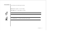
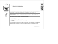
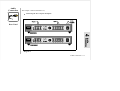
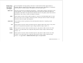
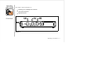
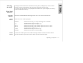
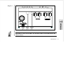
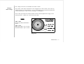
THE SEER
PREAMPLIFIER
BY TUBE TECHNOLOGY
~ USER'S MANUAL ~
Applicable to
PHONO & LINE MODEL
TT PART No. SeM-02
Printed in England
1st Edition - May 1994
i
Introduction
Thank you for selecting the Tube Technology Seer Preamplifier.
Please read through this manual so you will know how to operate your Seer Preamplifier
properly. After you have finished reading this manual, please put it away in a safe place for
future reference.
We have done our utmost in the design and build of the Seer to ensure you a low
maintenance, trouble free preamplifier that will bring you many years of pleasure as an important
part of your hi-fi system.
Please do not forget to complete and return the enclosed registration card.
We wish you many hours of musical enjoyment !
ii
Contents
1.
2.
3.
4.
5.
6.
7.
8.
9.
10.
Getting Started
Unpacking your Seer Pre-Amplifier
Mains Connection
Connecting The Seer to the household mains supply
Wiring a Mains Plug - UK
Earthing Arrangements
Installation
Installing & ventilation of your preamplifier
Audio Connection - Rear Panel
Connecting the Seer's Inputs & Outputs.
Operating your System - Front Panel
Switching your Seer On & Off
Front Panel Functions
Operational Notes
Running-In
Burning in your Preamplifier
Tube Information
Maintenance
Care and Cleaning of your preamplifier
Troubleshooting
Changing Mains Voltage
Specifications
Guarantee
Claims under the Guarantee
Tube Renaissance
1-1
2-1
2-1
2-2
3445555-
1
1
2
1
2
2
3
6-1
6-1
7-1
7-3
7-5
8-1
9-1
9-2
10- 1
Contents - 1
Conventions
This manual uses the following conventions;
Bold indicates emphasis or a minor heading.
Italic Bold refers to a sub heading of a chapter.
This symbol refers to Notes containing important information set off from the text.
THIS SYMBOL REFERS TO CAUTION MESSAGES AND PROCEDURES WHICH IF
NOT OBSERVED CAN LEAD TO DAMAGE OR INJURY
Contents - 2
Getting
Started
This chapter contains information on;
Unpacking your Seer Preamplifier
Unpacking
Your preamplifier is packed in "jiffy-cell" support foam. Grip the top of this foam and simply pull it
out of the box. The Seer is then left sitting on its middle support and can be lifted out.,
All packing should be retained. Amplifiers returned under guarantee are only accepted in their
original packaging.
The following items are included in the packaging of the Seer;
1x
1x
1x
1x
Seer Preamplifier
Reference Manual & Registration Card
IEC Mains Leads (only on serial nos. 6022 and up)
Allen Key
Your pre-amplifier is supplied with the tubes already in place. Check through the mesh windows on
the top lid making sure that the (2 x LINE) (4 x PHONO) tubes have not worked free in transit.
Getting Started 1-1
Mains
Connection
This chapter contains information on;
Connecting the Seer to the household mains supply.
Wiring a mains plug (UK)
Earthing arrangements
Mains
Connection
Earthing
Arrangements
Your Seer plugs into the mains supply via the IEC socket located on the back panel (Only on
Models Serial No. 6022 & onwards, models preceeding this have a flying mains lead
See diagram 1). The Seer has been factory set to the correct mains voltage for your country.
The voltage setting is marked on the serial badge, located on the rear panel of the unit. (See
diagram 1). Check that this voltage complies with your local supply.
When using a pre-power combination it is essential to ensure that no "earth loops" occur, this is
when too many earths are connected to the mains earth, resulting in a feint low frequecy hum
through the system. If neccessary you may not need to earth the preamplifier to the mains earth,
consult the handbook for your power amplifier if you are unsure. .
DO NOT CONNECT/SWITCH-ON THE MAINS SUPPLY TO THE AMPLIFIER BEFORE
COMPLETING ALL OTHER CONNECTIONS. IF YOU ARE IN ANY DOUBT REGARDING MAINS CONNECTIONS PLEASE DO NOT PROCEED ANY FURTHER WITHOUT
CONSULTING YOUR DEALER.
Mains Connection 2 - 1
Wiring a
Mains Plug
Export units for certain markets have a moulded mains plug fitted to comply with local
standards. If your mains supply lead does not have a plug fitted, the coloured wires should be
connected to the appropriate plug terminals in accordance with the following code.
Wire Colour
Label on Plug
GREEN/YELLOW E or EARTH or
BLUE
N or NEUTRAL or BLACK
BROWN
L or LIVE or RED
If your mains plug has a fuse, please fit a fuse with 5A rating.
IF YOUR SEER IS NOT SET CORRECTLY FOR THE LOCAL SUPPLY OR IF YOU
INTEND TO MOVE THE AMPLIFIER TO A LOCATION WHERE THE SUPPLY IS AT A
DIFFERENT VOLTAGE, IT WILL BE NECESSARY TO CHANGE THE VOLTAGE
SWITCH ON THE SEER. IF THIS IS NECCESSARY PLEASE REFER TO Changing
Voltage IN THE MAINTENANCE CHAPTER.
DO NOT SWITCH ON THE AMPLIFIERS BEFORE COMPLETING THE AUDIO
CONNECTIONS.
Mains Connection 2 - 2
Installation
This chapter contains information on;
Installing and Ventilation of your Preamplifier
Ensure that the amplifier is placed in a stable location that is able to accept its weight the Seer
weighs approx. 6 kilograms.
Installing &
Ventilation
It is not recommended that preamplifier is installed in a cupboard or in any enclosed area if
there is not sufficient air space and ventilation to keep it cool. A minimum distance of four
inches above the preamplifier should be allowed as this is where most of the heat is generated.
Dedicated racks are available for housing your tube equipment, contact your dealer or Tube
Technology. Do not locate the preamplifier close to radiators or any other heat source, this
could increase the operating temperature. Do not directly block the ventillation grilles on the
top cover of the preamplifier.
Do not locate the preamplifier too close to a turntable, as the cartridge could pick up hum from
the power transformer.
DO NOT SIGHT THE PREAMPLIFIER OR POWER SUPPLY NEAR WATER OR HEAVY
MOISTURE, THE VENTILATION GRILLES ON THE TOP OF THE UNIT ARE AN EASY
ACCESS POINT FOR MOISTURE TO ENTER.
Installation 3 - 1
Audio
Connection
This chapter contains information on;
Connecting the Seer's Inputs & Outputs
Rear Panel
Diagram 1
Audio Connection 4 - 1
Connecting
the Inputs
& Outputs
PRE OUT
REC
GROUND
CD
Your Preamplifier uses high quality connectors to ensure that maximum signal transfer is
possible, therefore ensure that all cables used for connection to the preamplifier are terminated
with connectors of similar quality. See Diagram 1 for Rear Panel layout.
One pair of connectors are offered for the outputs.. Connect these outputs to the inputs of your
power amplifier. If you are using directional cables ensure the arrows point away from the
preamplifier. Red denotes the right channel and black the left. The quality of this interconnect is
important for sonic clarity, consult your dealer if in doubt.
These outputs provide an audio output suitable for connection to the RECORD input of a tape
deck. The source to be recorded is selected by means of the input selector switch on the right
hand side of the front panel. See Diagram 2.
This terminal is used to ground any inteconnecting leads which have a separate ground
connection.
These inputs are used to connect the audio output of a digital compact disc player or any other
audio hi-fi component that produces output voltage within the range 150mV-3 V.
AUX 1
TAPE
These inputs are used to connect the audio output of a tape deck or audio section of a video
recorder or any other audio hi-fi component that produces output voltage within the range
150mV - 1V.
AUX 2
These inputs are used to connect the audio output of a tape deck or audio section of a video
recorder or any other audio hi-fi component that produces output voltage within the range
150mV - 1V. If you have a PHONO SEER this input is not functional
Audio Connection 4 - 2
TUNER
These inputs are used to connect the audio output of a tuner or any other audio hi-fi component
that produces output voltage within the range 150mV-1 V.
PHONO
These inputs are suitable for both moving magnet and high output type moving coil cartridges,
with outputs in the order of plus 0.5millivolts. An external step-up device is required for use
with low output moving coil cartridges. If you have a Line Seer this input is absent.
IEC
INLET
Only on Models Serial No. 6022 and upwards.
The IEC connector on the rear panel, connects to the mains supply via the mains cable supplied.
DO NOT SWITCH-ON THE SYSTEM UNTIL YOU HAVE READ CHAPTER 5 Operating
Your System.
Audio Connection 4 - 3
Operating
your System
This chapter contains information on;
Switching your preamplifier ON and OFF.
Front Panel Functions
Operational Notes
Front Panel
Diagram 2
Operating your System 5 - 1
Switching
On & Off
Rotating the knob located on the left hand side of the panel (see Diagram 2) in the clockwise
direction switches the preamplifier ON and counter-clockwise switches it OFF.
It is always wise to switch on your preamplifier first and then the power amplifier, this always
ensures a trouble free warm up.
Front Panel
Functions
Operation
Indicator
Source
Selector
This LED is illuminated RED indicating that the unit is switched on and functional.
Selects the source of the input signal.
PHONO
CD
AUX 1
AUX 2
TAPE
TUNER
Volume
Control
- Selection for listening to a Vinyl Recording from a Turntable
Not functional in a Line Level Seer
- Selection for listening to a Compact Disc
- Selection for listening to an Auxiliary Input such as TV or Video
- Selection for listening to an Auxiliary Input such as TV or Video
Not functional in a Phono Seer
- Selection for listening to a cassette tape
- Selection for listening to a radio broadcast
Controls the sound output level for both left and right channels. Counter-clockwise rotation
provides minimum output and clockwise rotation provides maximum output.
Operating your System 5 - 2
Operational
Notes
Some users of tube amplifiers believe that because tube amplifiers take some time to warm up
that they should be left on all the time. The Seer preamplifier reaches peak performance levels
15-20 minutes after switch on. Unless absolutely necessary it is not recommended that you
leave your preamplifier permanently switched on, this only wastes electricity and tube life, but
if necessary the Seer premplifier is quite capable of being left switched on for very long periods
of time.
Operating your System 5 - 2
Running-In
This chapter contains information on;
Burning-In your Preamplifier
Tube Information
Burning-In
Amplifiers
"Burning-In" is a generic term given to the basic 'running-in' of the amplifier. You may notice a
slight 'electronic-smell' from your preamplifier during the first few days of operation. This smell
is usually caused by various prints and dyes used on the components which takes some time to
evaporate This is quite normal and there is no need for concern as your preamplifier has been
extensively soak tested before leaving the factory. This burning-in process continues with your
use of the preamplifier.
This process simply allows for new components like tubes, capacitors and resistors to settle and
'sweeten' enhancing the amplifiers sonic performance. An estimated 40 hours of operation
allows your Seer this running-in period.
Tube
Information
As with all tubes, their qualities degrade with age due to cathode emission (a natural process
common to all tubes) A typical life span of a twin triode signal tube as used in the Seer would
be approx. 6000 hours, after which time they should be replaced, thus keeping your
preamplifier at it's maximum sonic performance; Refer to the Maintenance chapter.
Running-In 6 - 1
Maintenance
This chapter contains information on;
Care and Cleaning of your Preamplifier
Troubleshooting
Changing Mains Voltage
Care &
Cleaning
All polished metal parts on your amplifier are unlacquered. These metal parts will in time
lack lustre due to oxidisation. They can easily be restored to original condition by using a
mild metal polish (such as duraglit) and a soft polishing cloth. Do not clean the polished parts
with water as this smears the surface and can leave water marks.
Anodised parts such as the front panel and top covers of the Seer & painted parts such as the
bottom cover are best cleaned with a damp cloth then buffed with a dry cloth. DO NOT apply
any kind of polish. For very stubborn marks a mild solvent such as methylated spirits can be
applied.
ENSURE THAT THE UNITS HAVE BEEN DISCONNECTED FROM THE MAINS
BEFORE COMMENCING ANY CLEANING OPERATIONS.
Maintenance 7 - 1
Diagram 3
WARNING ELECTRIC SHOCK HAZARD - HIGH VOLTAGES EXIST WITHIN THE
EQUIPMENT EVEN AFTER THE UNIT HAS BEEN DISCONNECTED FROM THE
MAINS SUPPLY.
Maintenance 7 - 2
Troubleshooting
SYMPTOM
REMEDY
Preamplifier switches on but there is no
sound from the system.
1. Look in the top window of the preamp to see if
the tubes are glowing, this is an indicaton that the
power supply is operating the preamp.
2. Ensure you have connected the outputs of the
preamp to the inputs of your amplifier.
Preamplifier does not switch on
1. Ensure IEC plug on the mains lead is a snug fit
into the IEC connector on the rear panel.
2. Check the mains fuse located inside the fuse
holder next to the switch . Disconnect mains
connector before changing fuse. see diagram 3.
With volume at zero hum is present
1. Check that the the earthing arrangements are
correct - see chapter 2. Only one amplifier
component should go to the mains earth.
When looking in the top window of the
preamp, a tube seems to have gone milky
white, it does not light up when the unit is
switched on
1. The vacuum of this tube has escaped through a
small crack in the glass. When inserting tubes into
their sockets, place a finger behind the socket
ensuring the pcb does not flex and the tube fits into
the socket with little stress. Stress at the base of the
tube around the pins can cause tiny fractures in the
glass which develop in time.
Maintenance 7 - 3
Troubleshooting
SYMPTOM
REMEDY
After replacing a tube, with the volume
mid-way, I can hear my hand touching the
preamplifier through the loudspeakers, like
an echo.
1. The tube you have replaced is ' microphonic '.
This is particularly noticeable if the tube has been
fitted in the phono stage.
2. Change the tube for another.
After de-selecting an input I can still hear
it in the background.
1. This is caused by breakthrough on the selector
switch, it cannot be avoided, unless complicated
sound degrading circuitry is employed. The best
advice is to switch of the offending signal, this is
particularly true for tuners which are often left on.
UNDER NO CIRCUMSTANCES SHOULD AN UNQUALIFIED PERSON REMOVE THE
COVERS OF AN AMPLIFIER. IF IN DOUBT PLEASE CONSULT YOUR DEALER OR
TUBE TECHNOLOGY.
Maintenance 7 - 4
The voltage on the Seer is switchable from 120V to 240V.
Changing
Mains Voltage
The primary of the mains transformer can be changed from 120V to 240V, this is done by
changing the taps on the transformer. It is recommend that only an experienced technician
carries out this task, or refer to Tube Technology. See diagram 4.
This is done by turning the switch located at the base of the Prophet Power supply to the
desired position. A large coin is best used for this task.
Settings
240V / 220V
Red & Org LINK, Blk & Blu to
switch
120V / 110V
Blk & Org LINK - pair to switch
Red & Blu LINK - pair to switch
Diagram 4
Maintenance 7 - 5
Specifications
Figures given below are for a typical Seer Pre Amplifier
Vacuum Tubes
ECC83/12AX7WB x 2 (LINE), x 4 (PHONO)
Output Voltage
5V max @ 300mV in
Frequency Response
LINE5Hz - 120 KHz @ 1W +/- 0.001dB
PHONO - 30 Hz - 30KHz +/- 3dB
Input Sensitivity
LINE - 300 mV (output 1V)
PHONO- 0.50mV, 150pF (output 1V)
Input Impedance
LINE - 200 Ohms
PHONO - 47 KOhms
Power Consumption
Quiescent = 28 watts
Voltage
110V, 120V, 220V, 230V, 240VAC
Dimensions
350 (W) x 250 (D) x 65 (H) mm
Weight
5.5 Kg,
Specifications 8 - 1
Guarantee
This chapter contains information on;
The Guarantee of your Seer Preamplifier
Tube Guarantee
Registration
Claims under this Guarantee
Guarantee
This equipment has been fully tested and a full record of these tests made before despatch
from the factory. Both the workmanship and the performance of this equipment are (*except
as set out below) guaranteed against defects for a period of TEN YEARS from the date of
purchase, provided that it was originally purchased from an authorised dealer under a
consumer sale agreement, at or near the recommended retail price. (The words "consumer
sale" shall be construed in accordance with section 15 of the Supply of Goods (Implied Terms)
act 1973).
This guarantee covers both labour and parts and is transferable to subsequent purchasers but
the liability of the manufacturers is limited to the cost of repair or replacement (at the
discretion of the manufacturers) of the defective parts and under no circumstances extends to
consequential loss, damage or shipping charges.
* These amplifiers only carry a ten year guarantee if used in conjunction with a Tube
Technology power-amplifier, otherwise a TWO YEAR guarantee applies.
Guarantee 9 - 1
The manufacturers can accept no responsibility for defects arising from accident, misuse, wear and
tear, neglect or through unauthorised adjustments and or repair, neither can they accept responsibility for damage or loss occurring during transit to or from the person claiming under this guarantee.
Tube
Guarantee
This equipment has a SIX MONTH guarantee on the tubes allowing for any manufacturing defects
to arise. If a tube is found to be defective it should be returned to the dealer or failing this, directly
to Tube Technology packed in its original packaging.
Registration
Please complete the registration card and return it to Tube Technology. Your guarantee is invalid
without registration. To transfer this guarantee to subsequent purchasers, the new owner must
notify Tube Technology of their name, address and serial numbers of the equipment.
Claims under this
Guarantee
This equipment should be packaged in the original packaging and returned to the dealer from whom
it was purchased or, failing this, any other authorised Tube Technology dealer. If it is not possible
to return the equipment by hand then it should be sent carriage prepaid by a reputable carrier.
Should the original packaging not be available replacement packaging can be purchased from the
manufacturers. The equipment should not be sent by post.
DO NOT CONSIGN THE EQUIPMENT TO TUBE TECHNOLOGY UNLESS YOU
HAVE FIRST BEEN SPECIFICALLY REQUESTED TO DO SO BY THE
MANUFACTURERS TECHNICAL SERVICE DEPARTMENT. DO NOT UNDER
ANY CIRCUMSTANCES ATTEMPT TO DISASSEMBLE THE EQUIPMENT
BEFORE DESPATCH.
Guarantee 9 - 2
If you have any difficulty complying with these requirements, please contact the manufacturers at
the following address:
TUBE TECHNOLOGY
COMPTON HOUSE
DREFACH
CARMARTHENSHIRE
SA14 7BA
UK
Tel: +44 (0) 1269 844771
Fax: +44 (0) 1269 833538
In either case you should state clearly your name and address, the date and place of purchase
together with a brief description of the fault experienced. In the event of equipment being returned
which on test is found to comply with the published specifications the manufacturers reserve the
right to charge a reasonable fee for testing the equipment and for return carriage.
The manufacturers are happy to answer any queries you may have regarding the use of this
equipment on the condition that this enquiry is by letter. You should state clearly the serial number
of the unit, the dealer from whom it was purchased and the date of purchase.
THIS GUARANTEE IN NO WAY VARIES OR REMOVES A PURCHASERS
STATUTORY RIGHTS.
Guarantee 9 - 3
Tube
Renaissance
Tube Renaissance
A possible expalnation of why tubes may sound
better than transistors.
From the late 1960’s, tubes were largely,
though not entirely, superceded by semiconductors in audio frequency amplifier designs. This
was an inevitable consequence of a continuing
quest for new techniques. Semiconductors
(Transistors and Integrated Circuits) have certain and obvious advantages: their small size,
absence of heaters, low voltage operation and
consequent opportunity to dispense with output
transformers may appear to make tubes obsolete. However, from about 1975 onward, there
has been a resurgence of interest in tubes; and it
seems worthwhile to consider why.
It is said by ‘hi-fi’ enthusiasts that tube
amplifiers sound better, that their distortion is
either lower or less noticable. Carefully conducted listening tests seem to bear this out,
although their results are difficult to interpret. If
there really are subjective differences to a
listener between tubes and semiconductor amplifiers, can they be explained technically?
One thing should be clearly understood: it is
possible to design either a tube or a semiconductor amplifier so that over a certain range
of output power its distortion will be so small
as to be imperceptable to the ear. Therefore,
if two similarly rated well-designed high
fidelity amplifiers, one using tubes and the
other using semiconductors, are compared in
the same listening conditions, correctly operated, their performance should be indistinguishable - and subjectively perfect.
Now, on the basis of measured performance,
many modern high fidelity semiconductor
amplifiers are actually superior to the older
tube amplifiers, which were already good
enough for their distortion tobe imperceptable; so how can here be subjective differences? It seems that there cannot be any,
while the amplifiers are correctly operated:
and this may be the key to the mystery, for
there are two major problems: one is that it is
extremely difficult to avoid occasional over
driving of an amplifer, because of the very
Tube Renaissance 10 - 1
large dynamic range of the audio signal; and
the other is that the loading is not always
resistive. It is under these (usually unintentional) wrong conditions that differences may
show up.
sound level. One has no way in advance of
knowing in advance whether there is an
exceptionally loud passage coming that will
over drive the amplifier. Bursts in excess of
30dB above the average are quite rare.
Let us consider the over driving first. Owing
to continual improvements in recording and
playback technique, the possible dynamic
range of music signals- from either disc or
tape - is greater now than it used to be. As a
tentative estimate, it appears that the loadest
passage of a modern disc recording maybe
40dB above the average sound level. Now it
may be said that amplifiers in a high fidelity
system ought theoretically to be able to
reproduce the loudest of loud bursts without
distortion. However, to allow for 40dB above
50mW - not a very high listening level - a
power capability of 500W would be required;
and further developments may make the
figure even greater. One seems to hear a cry
of “where is it all going to end?” Anyway,
when setting up an amplifier system one
adjusts the gain to give the prefered average
If we accept, then, that occasional over
driving is virtually inevitable, how will the
amplifier behave? We now come to the first
possible reasons why tubes and semiconductors may “sound different”.
Presented with an over large signal, tubes
merely clip the peaks, delivering a flat-topped
waveform while the over driving is taking
place. The limiting may occur at the grid as
the circuit resistances are commonly such as
to prevent it from being driven more than
slightly positive, or it may be the results of
coalescence of characteristic curves at lower
voltages. The ear is surprisingly tolerant of
such clipping when it occurs only on these
occasional load bursts.
The semiconductors used in audio amplifiers
are virtually always bipolar transistors, either
discrete or integrated. They require base
Tube Renaissance 10 - 2
current to be applied in order to make
collector current flow. Now transistor
amplifiers normally incorporate a large
amount of negative feedback, and, when such
an amplifier limits, some of its stages are
driven very hard, so that extra large base
currents are drawn. If any capacitors are
affected by such current pulses, the result may
well be that a brief over driving is followed
by a comparatively long recovery signal,
which would be much more noticeable than
mere clipping of peaks. Even with dc
coupling, there may still be capacitors that can
cause such extra signals.
There is a further effect that takes place in the
transistor itself, because of the phenomenon of
charge storage. A transistor that has been
conducting does not switch off immediately
when the forward base bias is removed, but
continues to take collector current until all the
relevant charge carriers that are in transit have
been swept out. The effect is most pronounced
in a transistor that has been turned on hard: in
fact the larger the base current the longer will
be the turn-off time. In audio transistors that
have been over driven this time may be of the
order of hundreds of microseconds, so this
effect can also give rise to spurious signals.
When it is realised that even the most critical
listener cannot detect peak clipping of
occasional short loud bursts by as much as
6dB, we can understand why it is sometimes
said that a 50W tube amplifier can sound
equal to some 200W transistor amplifiers. A
tube amplifier can be quite grossly over
driven with little or no subjective effect on
sound quality, whereas most transistor
amplifiers probably cannot.
The other kind of unintentional wrong
operation we have to consider is incorrect
oading. The impedance of a loudspeaker
system is by no means constant: a so-called 8
ohm system may well present anything from 4
to 16 ohms over the audio frequency range,
and be highly reactive at some frequencies. It
is under reactive load conditions with large
signals that another major difference appears
between tubes and transistors. The combina-
Tube Renaissance 10 - 3
tion of simultaneous high voltage drop and
high current occurring for brief periods at
certain parts of the elliptical load line does not
normally affect tubes, may cause a
catastrophic second breakdown effect, in
which a permanent short circuit develops - not
to be confused with ordinary avalanche break
down, which is a reversible phenomenon.
The risk of second break down may be
avoided by using transistors with sufficiently
high ratings to be well clear of the effect, if
available; but the alternative commonly
employed is to incorporate protective circuitry
that cuts the signal whenever the output
transistors are subject to a dangerous
combination of voltage and current, and this
obviously has a very unpleasant effect on the
sound. The purpose of these remarks is not to
denigrate transistor amplifiers, but to present a
case for tubes, and to show that there may be
technical reasons for the supposedly
subjective effects that have been attributed to
transistors. Ways may be found of eliminating
or obviating these effects in a transistor
amplifier design; but there is a simplicity
about tube circuitry which may appeal to
many audio engineers, both professional and
amateur.
A further point can be made in favour of
tubes, concerning cooling. Output transistors
have to be conduction cooled, preferably by
some method that does not heat up other
semiconductors in the circuit. This requires
some rather bulky metalwork thermally
isolated from the rest of the chassis. Glass
envelope tubes, on the other hand, looses most
of their heat by a mixture of convection and
radiation.
A brief reference may be in order here about
what is usually considered to be main
disadvantage of a tube amplifier, the output
transformer. It is indeed a heavy and costly
item, to be set against the relative simplicity
of circuit and various other advantages that
have here been attributed to the tube
equipment. However it can enable the
amplifier to work into more than one load
impedance, whilst a transformerless
Tube Renaissance 10 - 4
semiconductor amplifier designed to drive an
8 ohm load would usually deliver only half its
normal power into a 16 ohms, and might be
damaged if operated with 4 ohms. Also, with
an output transformer provided that it is
correctly loaded, the amplifier input sensitivity
without feedback is the same whatever the
value of load impedance; and by taking the
negative feedback connection from a fixed
point on the secondary winding the sensitivity
with feedback can be made similarly
independent of load impedance: in other
words, the number of decibels of feedback
and therefore the reduction of distortion,
damping factor and so on, are the same
whatever the load. So there is something to be
said for having an output transformer.
practise; and not only the output stage, but
also low level stages are involved in these.
Tubes have a distict advantage in operation
with reactive loads, and are easier to cool.
Even the need for an output transformer is not
quite such an unmitigated drawback as it may
sometimes seem.
These may be some of the reasons why a
substantial part of the audio amplifier market
has stayed with tubes during the “transistor
era”, and why there has recently been such a
remarkable “Tube Renaissance”.
Perhaps enough has been said to suggest at
least that the advantages are not entirely on
the side of semiconductors, and that points
can be made in favour of tubes, concerning
both performance and convenience in use.
Semiconductors may produce un-welcome
effects on over driving, so difficult to avoid in
Tube Renaissance 10 - 5


![View User`s Manual [US] - Acoustic Amplification](http://vs1.manualzilla.com/store/data/005834670_1-839e21e8bc31a6b298042e7e04804c8b-150x150.png)