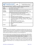
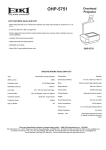
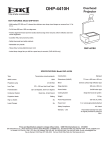
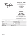
1
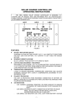
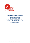
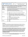
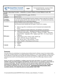
SYNERGY DMA
DUAL MONO
POWER AMPLIFIER
BY TUBE TECHNOLOGY
~ USER'S MANUAL ~
TT PART No. Sy2M-01
Printed in England
1st Edition - September
1995
i
The Synergy
Synergy -(defn); Simultaneous action of separate instances
which, together have a greater total effect then the sum of
their individual accomplishments.
ii
Introduction
Thank you for selecting the Synergy Amplifier from Tube Technology.
We hope The Synergy will bring you many years of pleasure as an important part of your hi-fi
system.
Please read through this manual so you will know how to operate your Synergy amplifier
properly. After you have finished reading this manual, please put it away in a safe place for
future reference.
Please do not forget to complete and return the enclosed registration card.
We wish you many hours of musical enjoyment !
iii
Contents
1.
2.
3.
4.
5.
6.
7.
8.
9.
10.
Getting Started
Unpacking your Synergy Amplifier
Checking and Installing the tubes
Mains Connection
Connecting the Synergy to the household mains supply
Wiring a Mains Plug - UK
Installation
Installing & ventilation of your amplifier
Audio Connection - Rear Panel
Connecting the Synergy's Inputs
Connecting your Synergy to the loudspeakers
Operating your System - Front Panel
Switching your amplifier On & Off
Control & Front Panel Functions
Operational Notes
Running-In
Burning in your Amplifier
Tube Information
Maintenance
Care and Cleaning of your amplifier
Adjusting Bias using the OBBC system
Troubleshooting
Specifications
Guarantee
Claims under the Guarantee
Tube Renaissance
1
2-4
5
6
7
8
9-10
11
12-13
14
15
15
16
16-17
18
19
20-21
21-22
23-27
Contents - 1
Conventions
This manual uses the following conventions;
Bold indicates emphasis or a minor heading.
Italic Bold refers to a sub heading of a chapter.
This symbol refers to Notes containing important information set off from the text.
THIS SYMBOL REFERS TO CAUTION MESSAGES AND PROCEDURES WHICH IF
NOT OBSERVED CAN LEAD TO DAMAGE OR INJURY
Contents - 2
Getting
Started
This chapter contains information on;
Unpacking your Synergy Amplifier
Checking & Installing the Vacuum Tubes
Unpacking
Your amplifier is packed in "jiffy-cell" support foam. Grip the top of this foam and simply pull it
out of the box. The Synergy is then left sitting on its bottom support. Lift out carefully,
remembering that the centre of gravity is biased towards the rear of the unit due to the heavy
transformers.(It may be neccessary for another person to help manouvre the unit as it is very heavy)
All packing should be retained. Amplifiers returned under guarantee are only accepted in their
original packaging.
The following items are included in the packaging of a Synergy No.1;
1
12
1
1
1
1
x
x
x
x
x
x
Synergy DMA Amplifier
EL34 Output Vacuum Tubes
Bias Adjust trimmer
Reference Manual & Registration Card
IEC Mains Lead
Spare mains fuse (6.3A T) (8.0A T 100V/120V)
Getting Started 1
Installing
the Tubes
The Synergy is usually shipped with its output tubes packed separately, this helps protect them
during transit.
If you have ordered a protection grille with your amplifier the output tubes have already been
installed and there is no need to read this section.
The input and driver tubes are already in place inside the amplifier, please do not remove these,
as they have been calibrated.
The vacant tube sockets on the amplifier are numbered 1 to 6, for the left hand channel of the
amplifier and 7 to 12 for the right hand side.
(See diagram 1)
The output tubes which are packed separately locate in these sockets. The relevant tube number
is printed on the inside flap of each box, or if you have a Gold Aero model, on the tube caps .
Remove the tube carefully from its packing and install it in its matching socket, as labeled in
Diagram 1.
Ensure that the keyway on the base of the tube lines up with the keyway on the tube socket.
Each tube must be inserted carefully. Align the tube pins in the centre of the receptacles on the
tube base, then apply gentle downwards pressure, firmly pushing the tube home into its base.
Do not rock the tube from side to side as the keyway on the tube base will fracture.
Getting Started 2
Diagram 1
Master Bias
Adjustment
(Left Channel)
Getting Started 3
Diagram 2 shows the arrow
pointing to the positions of
the keyways on the EL34
and the keyways on the
amplifiers tube sockets.
Tube Base
Tube Socket
Diagram 2
If the glass on any of the tubes is cracked or broken do not use, consult your dealer for a
replacement and refer to the Maintenance chapter for instructions on how to replace a faulty
tube.
Remove the tubes from their cartons and fit - one at a time. This will ensure that each tube is
in its correct socket as calibrated when leaving the factory. If you should mix up the order
refer to replacing a tube in the maintenance chapter.
Getting Started 4
Mains
Connection
This chapter contains information on;
Connecting the Synergy to the household mains supply.
Wiring a mains plug (UK)
Mains
Connection
Your Synergy amplifier plugs into the mains supply via the IEC socket located on the back
panel (see diagram 3). The amplifier has been factory set to the correct mains voltage for your
country. The voltage setting is marked on the serial badge, located on the rear panel. (See
diagram 3). Check that this voltage complies with your local supply. Also make sure that your
mains outlet is able to deliver the required current for the equipment plugged into it. The
wattage rating is also marked on the serial badge.
DO NOT CONNECT/SWITCH-ON THE MAINS SUPPLY TO THE AMPLIFIER BEFORE
COMPLETING ALL OTHER CONNECTIONS. IF YOU ARE IN ANY DOUBT REGARDING MAINS CONNECTIONS PLEASE DO NOT PROCEED ANY FURTHER WITHOUT
CONSULTING YOUR DEALER.
Mains Connection 5
Wiring a
Mains Plug
Export units for certain markets have a moulded mains plug fitted to comply with local
standards. If your mains supply lead does not have a plug fitted, the coloured wires should be
connected to the appropriate plug terminals in accordance with the following code.
Wire Colour
Label on Plug
GREEN/YELLOW E or EARTH or
BLUE
N or NEUTRAL or BLACK
BROWN
L or LIVE or RED
If your mains plug has a fuse, please fit a fuse with 13A rating.
If your amplifier is not set correctly for the local supply or if you intend to move the amplifier
to a location where the supply is at a different voltage, it will be necessary to change the voltage
taps on the mains transformer. We recommend that this is done by an experienced technician.
Refer to changing voltage in the maintenance chapter.
DO NOT SWITCH ON THE AMPLIFIERS BEFORE COMPLETING THE
AUDIO CONNECTIONS.
Mains Connection 6
Installation
This chapter contains information on;
Installing and Ventilating your amplifiers
Installing &
Vetilation
Ensure that the amplifier is placed in a stable location that is able to accept its weight each unit
weighs 46 kilograms.
It is not recommended that amplifiers are installed in cupboards or in any enclosed area if there
is not sufficient air space and ventilation to keep them cool. A minimum distance of six inches
above the amplifier should be allowed as this is where most of the heat is generated.
Dedicated racks are available for housing your tube equipment, contact your dealer or Tube
Technology. Do not locate the amplifier close to radiators or any other heat source, this could
increase the operating temperature.
Do not locate the amplifier too close to a turntable, as the cartridge could pick up hum from the
power transformers.
THE OUTPUT TUBES REACH VERY HIGH TEMPRATURES!! DO NOT TOUCH UNDER
ANY CIRCUMSTANCES. FOR EXTRA PRECAUTIONS A TUBE PROTECTION GRILLE
IS AVAILABLE.
Installation 7
Audio
Connection
This chapter contains information on;
Connecting the Synergy's Inputs & Output
Connecting your Synergy to the loudspeakers.
Rear Panel Information
Connecting
the Inputs
& Output
AUDIO
INPUTS
Your amplifier uses high quality connectors to ensure that maximum signal transfer is possible,
therefore ensure that all cables used for connection to the amplifier are terminated with
connectors of similar quality.
These connectors for both left and right channels, connect to your preamplifier.
These connectors are safety RCA jacks, which have a negative retractible spring, for the short
circuit protection of any RCA plug. This allows you to plug and unplug your inter-connects
without having to switch off the amplifier.
Audio Connection 8
TUBE
PROTECTION
IEC
INLET
MAINS FUSE
MAINS
SWITCH
Connection to
Loudspeakers
The Synergy incorporates a special resettable fuse for each of the twelve output tubes. This
protects the amplifier from the potential damage that may be caused to the amplifier
electronics if an output tube should go faulty. When activated the fuse stops the tube from
drawing current, the bias meter will display -1. Please note the filament will still be glowing.
The IEC connector on the rear panel, connects to the mains supply via the mains cable
supplied.
This fuse is rated at 6.3 A, and protects both the large dome shaped transformers.
This switches the amplifier On & Off, it has a red indicator when in the On position.
The loudspeaker outputs are suitable for driving loudspeakers with
impedances in the range of 6-8 ohms. The output terminals are 4mm
terminal posts and each will except two 4mm (banana) plugs or bare wire.
For bi-wiring use the side entry holes together with the front entry holes.
Connect the positive or (+) of the speaker cable to the red terminal on the
amplifier, and the negative or (-) to the black terminal on the amplifier.
DO NOT SWITCH-ON THE SYSTEM UNTIL YOU HAVE READ CHAPTER 5 Operating
Your System.
Audio Connection 9
Rear Panel
Diagram 3
Audio Connection 10
Operating
your System
This chapter contains information on;
Switching your amplifier ON and OFF.
Control & Front Panel Functions
Operational Notes
Switching
On & Off
The main switch for switching the Synergy On & Off is located on the rear panel,
(See diagram 3) it has a red indicator strip to indicate the On position. With this switch in The
ON position, the unit can now be operated from the switch in the centre of the control panel.
OPERATE indicates operation of the unit and STANDBY switches the amplifier Off.
Front Panel
Diagram 4
Operating your System 11
After switch on there is a delay of approx. 15 seconds before the main HT is switched, each
channel is switched On separately, an audible thump is heard from the mains transformer on
each channel as they power up, this is due to pole reversal which is quite normal for large power
transformers. The indicators on the front panel change from Amber to Green as each channel is
powered up.
Front Panel
Functions
Left & Right
Status Indicators
These LED's are bi-colour and are illuminated in either two colours. GREEN indicates that the
unit is switched on and functional, AMBER indicates that the unit is in Standby.
Operating your System 12
Diagram 5
Control Panel
Operating your System 13
Operational
Notes
Some users of tube amplifiers believe that because tube amplifiers take some time to warm up
that they should be left on all the time. The Synergy amplifier reaches peak performance levels
15-20 minutes after switch on. Unless absolutely necessary it is not recommended that you
leave your amplifier permanently switched on, this only wastes electricity and tube life, but if
necessary the Synergy is quite capable of being left switched on for very long periods of time.
THE OUTPUT TUBES REACH VERY HIGH TEMPERATURES!! DO NOT TOUCH
UNDER ANY CIRCUMSTANCES. FOR EXTRA PRECAUTIONS A TUBE PROTECTION
GRILLE IS AVAILABLE.
The glass envelope surrounding the tube can reach temperatures of up to 300 degrees
centigrade. A tube is a perfectly safe device if not touched when it is operating, rather like a
hot light bulb. For owners of pets and young children we recommend a Tube Technology tube
protection grille.
It is quite normal for the amplifiers to produce a very small amount of mechanical hum when
they are in operation.. This is due to the large power transformers.
DO NOT REPEATEDLY SWITCH THE AMPLIFIER ON AND OFF. ONCE YOU HAVE
SWITCHED THE AMPLIFIER OFF, WAIT APPROX. 15 SECONDS BEFORE SWITCHING
IT ON AGAIN.
Operating your System 14
Running-In
This chapter contains information on;
Burning-In your Amplifier
Tube Information
Burning-In
Amplifiers
"Burning-In" is a generic term given to the basic 'running-in' of the amplifier. You may notice a
slight 'electronic-smell' from your amplifier during the first few days of operation. This smell is
usually caused by various prints and dyes used on the components which takes some time to
evaporate This is quite normal and there is no need for concern as your amplifier has been
extensively soak tested before leaving the factory. This burning-in process continues with your
use of the amplifier.
This process simply allows for new components like tubes, capacitors and resistors to settle and
'sweeten' enhancing the amplifiers sonic performance. An estimated 80 hours of operation
allows your Synergy amplifier this running-in period.
Tube
Information
Unlike most other amplifiers, we run our tubes with very little standing current, this conservative use of the tube provides an extended reliable tube life. As with all tubes, their qualities
degrade with age due to cathode emission (a natural process common to all tubes) A typical life
span of an EL34 output tube in a Synergy would be approx. 4000 hours, after which time they
should be replaced, thus keeping your amplifier at it's maximum sonic performance; Refer to
the Maintenance chapter.
Running-In 15
Maintenance
This chapter contains information on;
Care and Cleaning of your amplifier
Bias Measurements of the Output Tubes
Troubleshooting
Changing Mains Voltage
Care &
Cleaning
OBBC Bias
Measurement
All polished metal parts on your amplifier are unlacquered. These metal parts will in time
lack lustre due to oxidisation. They can easily be restored to original condition by using a
mild metal polish (such as duraglit) and a soft polishing cloth. Do not clean the units with
water as this smears the surface and can leave water marks. When dusting the amplifiers be
sure not to catch the tubes as this may crack the glass. Alternatively you can remove the
tubes (remembering the order they were removed in) and clean the amplifier. Anodised parts
such as the front panel and control panel & painted parts such as the bottom cover are best
cleaned with a damp cloth then buffed with a dry cloth.
The Synergy amplifier uses a fixed bias system that requires very little attention. It is
necessary to re-adjust the bias if you fit a new tube to the amplifier, or if the order of the
tubes shipped with the amplifier has been mixed up. The Synergy uses an On Board Bias
Control (OBBC) to adjust the amount of bias on each tube. This metering system is located
behind the removable door in the middle of the control panel. On lifting this door the
amplifier automatically switches into mute, this is neccessary to adjust the bias. Follow the
procedure in table 1 to adjust the bias.
Maintenance 16
Step
Table 1
Action
Remark
1.
Remove the door in the centre of the
control panel, to reveal the meter.
Identify the 12 bias potentiometers,
located in the lower section of the
cutout. Gold screw heads are visible,
through round holes. 1-6 are for the
left hand channel and 7-12 for the
right hand channel.
2.
Rotate the black knob in the centre of the
meter to the relevant tube number. (see
diagram 1 for tube numbers)
The Liquid Crystal Display will now
give a reading of this particular tube.
3.
With the trimming tool provided adjust
the bias potentiometer gold screw head
until the meter gives a readout of 35.0.
This action should be carried out after
the amplifier has warmed up for at
least 5 minutes.
4.
If you are unable to bias a tube to 35 it is
possible to adjust the master bias for extra
voltage range. (see diagram 1)
This adjustment is very critical and only
needs a small turn for a large change in
reading.
UNDER NO CIRCUMSTANCES SHOULD AN UNQUALIFIED PERSON REMOVE THE
COVERS OF AN AMPLIFIER.
Maintenance 17
Troubleshooting
SYMPTOM
REMEDY
Amplifier switches on but there is no
sound from the system.
1. Check you have connected the source you are
trying to play ie. cd player to the relavant RCA
input connector on amplifier
2. Check that the loudspeaker connections have been
made.
3.Ensure the amplifier has its OBBC lid on, and it is
not in mute.
Amplifier does not switch on
1. Ensure IEC plug on mains lead is a snug fit.
2. Check the mains fuse located on the rear panel
see diagram 3.
Tubes Pulsate and glow blue
2. Ensure you have not switched the amplifier On &
Off without waiting at least 30 secs.
A tube or tubes glow very bright cherry
red, shortly after switch on.
(Do not confuse with normal filament
glow)
1. Turn amplifier off imediately.
2. Tube is faulty, check this tube with the OBBC
1. The tube you have replaced is ' microphonic '.
This is particularly noticeable if the tube has been 2.
Change the tube for another.
Maintenance 19
Specifications
Figures given below are for a typical Synergy Power Amplifier
Vacuum Tubes
EL34/6CA7 x 12
ECC81/12AT7 x 4 (Driver Stage)
Output Power
150 watts + 150 watts (8 ohms)
Frequency Response
LINE -
5Hz - 120 KHz @ 1W +/- 1dB
10Hz - 50KHz @ 150W +/- 1dB
Input Sensitivity
LINE -
775 mV (output 150W RMS )
Input Impedance
LINE -
130 KOhms
Output Load Impedance
6 - 8 Ohms (2 ohms switchable optional)
Power Consumption
Quiescent = 250W, Full power = 650W
Voltage
110V, 120V, 220V, 230V, 240VAC
Dimensions
470 (W) x 470 (D) x 150 (H) mm
Weight
45 Kilograms
Specifications 19
Guarantee
This chapter contains information on;
The Guarantee of your Synergy amplifier
Tube Guarantee
Registration
Claims under this Guarantee
Guarantee
This equipment has been fully tested and a full record of these tests made before despatch
from the factory. Both the workmanship and the performance of this equipment are
guaranteed against defects for a period of TEN YEARS from the date of purchase, provided
that it was originally purchased from an authorised dealer under a consumer sale agreement, at
or near the recommended retail price. (The words "consumer sale" shall be construed in
accordance with section 15 of the Supply of Goods (Implied Terms) act 1973).
This guarantee covers both labour and parts and is transferable to subsequent purchasers but
the liability of the manufacturers is limited to the cost of repair or replacement (at the
discretion of the manufacturers) of the defective parts and under no circumstances extends to
consequential loss, damage or shipping charges.
Guarantee 20
The manufacturers can accept no responsibility for defects arising from accident, misuse, wear and
tear, neglect or through unauthorised adjustments and or repair, neither can they accept responsibility for damage or loss occurring during transit to or from the person claiming under this guarantee.
Tube
Guarantee
This equipment has a SIX MONTH guarantee on the tubes allowing for any manufacturing defects
to arise. If a tube is found to be defective it should be returned to the dealer or failing this, directly
to Tube Technology packed in its original packaging.
Registration
Please complete the registration card and return it to Tube Technology. Your guarantee is invalid
without registration. To transfer this guarantee to subsequent purchasers, the new owner must
notify Tube Technology of their name, address and serial numbers of the equipment.
Claims under this
Guarantee
This equipment should be packaged in the original packaging and returned to the dealer from whom
it was purchased or, failing this, any other authorised Tube Technology dealer. If it is not possible
to return the equipment by hand then it should be sent carriage prepaid by a reputable carrier.
Should the original packaging not be available replacement packaging can be purchased from the
manufacturers. The equipment should not be sent by post.
DO NOT CONSIGN THE EQUIPMENT TO TUBE TECHNOLOGY UNLESS YOU
HAVE FIRST BEEN SPECIFICALLY REQUESTED TO DO SO BY THE MANUFACTURERS TECHNICAL SERVICE DEPARTMENT. DO NOT UNDER ANY
CIRCUMSTANCES ATTEMPT TO DISASSEMBLE THE EQUIPMENT BEFORE
DESPATCH.
Guarantee 21
If you have any difficulty complying with these requirements, please contact the manufacturers at
the following address:
TUBE TECHNOLOGY
TECHNOLOGY HOUSE
214 STATION ROAD
ADDLESTONE
SURREY KT15 2PH
ENGLAND
Tel: (44) 01932 821111
Fax: (44) 01932 821182
In either case you should state clearly your name and address, the date and place of purchase
together with a brief description of the fault experienced. In the event of equipment being returned
which on test is found to comply with the published specifications the manufacturers reserve the
right to charge a reasonable fee for testing the equipment and for return carriage.
The manufacturers are happy to answer any queries you may have regarding the use of this
equipment on the condition that this enquiry is by letter. You should state clearly the serial number
of the unit, the dealer from whom it was purchased and the date of purchase.
THIS GUARANTEE IN NO WAY VARIES OR REMOVES A PURCHASERS
STATUTORY RIGHTS.
Guarantee 22
Tube
Renaissance
Tube Renaissance
A possible expalnation of why tubes may sound
better than transistors.
From the late 1960’s, tubes were largely,
though not entirely, superceded by semiconductors in audio frequency amplifier designs. This
was an inevitable consequence of a continuing
quest for new techniques. Semiconductors
(Transistors and Integrated Circuits) have certain and obvious advantages: their small size,
absence of heaters, low voltage operation and
consequent opportunity to dispense with output
transformers may appear to make tubes obsolete. However, from about 1975 onward, there
has been a resurgence of interest in tubes; and it
seems worthwhile to consider why.
It is said by ‘hi-fi’ enthusiasts that tube
amplifiers sound better, that their distortion is
either lower or less noticable. Carefully conducted listening tests seem to bear this out,
although their results are difficult to interpret. If
there really are subjective differences to a
listener between tubes and semiconductor amplifiers, can they be explained technically?
One thing should be clearly understood: it is
possible to design either a tube or a semiconductor amplifier so that over a certain range
of output power its distortion will be so small
as to be imperceptable to the ear. Therefore,
if two similarly rated well-designed high
fidelity amplifiers, one using tubes and the
other using semiconductors, are compared in
the same listening conditions, correctly operated, their performance should be indistinguishable - and subjectively perfect.
Now, on the basis of measured performance,
many modern high fidelity semiconductor
amplifiers are actually superior to the older
tube amplifiers, which were already good
enough for their distortion tobe imperceptable; so how can here be subjective differences? It seems that there cannot be any,
while the amplifiers are correctly operated:
and this may be the key to the mystery, for
there are two major problems: one is that it is
extremely difficult to avoid occasional over
driving of an amplifer, because of the very
Tube Renaissance
23
large dynamic range of the audio signal; and
the other is that the loading is not always
resistive. It is under these (usually unintentional) wrong conditions that differences may
show up.
sound level. One has no way in advance of
knowing in advance whether there is an
exceptionally loud passage coming that will
over drive the amplifier. Bursts in excess of
30dB above the average are quite rare.
Let us consider the over driving first. Owing
to continual improvements in recording and
playback technique, the possible dynamic
range of music signals- from either disc or
tape - is greater now than it used to be. As a
tentative estimate, it appears that the loadest
passage of a modern disc recording maybe
40dB above the average sound level. Now it
may be said that amplifiers in a high fidelity
system ought theoretically to be able to
reproduce the loudest of loud bursts without
distortion. However, to allow for 40dB above
50mW - not a very high listening level - a
power capability of 500W would be required;
and further developments may make the
figure even greater. One seems to hear a cry
of “where is it all going to end?” Anyway,
when setting up an amplifier system one
adjusts the gain to give the prefered average
If we accept, then, that occasional over
driving is virtually inevitable, how will the
amplifier behave? We now come to the first
possible reasons why tubes and semiconductors may “sound different”.
Presented with an over large signal, tubes
merely clip the peaks, delivering a flat-topped
waveform while the over driving is taking
place. The limiting may occur at the grid as
the circuit resistances are commonly such as
to prevent it from being driven more than
slightly positive, or it may be the results of
coalescence of characteristic curves at lower
voltages. The ear is surprisingly tolerant of
such clipping when it occurs only on these
occasional load bursts.
The semiconductors used in audio amplifiers
are virtually always bipolar transistors, either
discrete or integrated. They require base
Tube Renaissance 24
current to be applied in order to make
collector current flow. Now transistor
amplifiers normally incorporate a large
amount of negative feedback, and, when such
an amplifier limits, some of its stages are
driven very hard, so that extra large base
currents are drawn. If any capacitors are
affected by such current pulses, the result may
well be that a brief over driving is followed
by a comparatively long recovery signal,
which would be much more noticeable than
mere clipping of peaks. Even with dc
coupling, there may still be capacitors that can
cause such extra signals.
There is a further effect that takes place in the
transistor itself, because of the phenomenon of
charge storage. A transistor that has been
conducting does not switch off immediately
when the forward base bias is removed, but
continues to take collector current until all the
relevant charge carriers that are in transit have
been swept out. The effect is most pronounced
in a transistor that has been turned on hard: in
fact the larger the base current the longer will
be the turn-off time. In audio transistors that
have been over driven this time may be of the
order of hundreds of microseconds, so this
effect can also give rise to spurious signals.
When it is realised that even the most critical
listener cannot detect peak clipping of
occasional short loud bursts by as much as
6dB, we can understand why it is sometimes
said that a 50W tube amplifier can sound
equal to some 200W transistor amplifiers. A
tube amplifier can be quite grossly over
driven with little or no subjective effect on
sound quality, whereas most transistor
amplifiers probably cannot.
The other kind of unintentional wrong
operation we have to consider is incorrect
oading. The impedance of a loudspeaker
system is by no means constant: a so-called 8
ohm system may well present anything from 4
to 16 ohms over the audio frequency range,
and be highly reactive at some frequencies. It
is under reactive load conditions with large
signals that another major difference appears
between tubes and transistors. The combina-
Tube Renaissance 25
tion of simultaneous high voltage drop and
high current occurring for brief periods at
certain parts of the elliptical load line does not
normally affect tubes, may cause a
catastrophic second breakdown effect, in
which a permanent short circuit develops - not
to be confused with ordinary avalanche break
down, which is a reversible phenomenon.
The risk of second break down may be
avoided by using transistors with sufficiently
high ratings to be well clear of the effect, if
available; but the alternative commonly
employed is to incorporate protective circuitry
that cuts the signal whenever the output
transistors are subject to a dangerous
combination of voltage and current, and this
obviously has a very unpleasant effect on the
sound. The purpose of these remarks is not to
denigrate transistor amplifiers, but to present a
case for tubes, and to show that there may be
technical reasons for the supposedly
subjective effects that have been attributed to
transistors. Ways may be found of eliminating
or obviating these effects in a transistor
amplifier design; but there is a simplicity
about tube circuitry which may appeal to
many audio engineers, both professional and
amateur.
A further point can be made in favour of
tubes, concerning cooling. Output transistors
have to be conduction cooled, preferably by
some method that does not heat up other
semiconductors in the circuit. This requires
some rather bulky metalwork thermally
isolated from the rest of the chassis. Glass
envelope tubes, on the other hand, looses most
of their heat by a mixture of convection and
radiation.
A brief reference may be in order here about
what is usually considered to be main
disadvantage of a tube amplifier, the output
transformer. It is indeed a heavy and costly
item, to be set against the relative simplicity
of circuit and various other advantages that
have here been attributed to the tube
equipment. However it can enable the
amplifier to work into more than one load
impedance, whilst a transformerless
Tube Renaissance 26
semiconductor amplifier designed to drive an
8 ohm load would usually deliver only half its
normal power into a 16 ohms, and might be
damaged if operated with 4 ohms. Also, with
an output transformer provided that it is
correctly loaded, the amplifier input sensitivity
without feedback is the same whatever the
value of load impedance; and by taking the
negative feedback connection from a fixed
point on the secondary winding the sensitivity
with feedback can be made similarly
independent of load impedance: in other
words, the number of decibels of feedback
and therefore the reduction of distortion,
damping factor and so on, are the same
whatever the load. So there is something to be
said for having an output transformer.
practise; and not only the output stage, but
also low level stages are involved in these.
Tubes have a distict advantage in operation
with reactive loads, and are easier to cool.
Even the need for an output transformer is not
quite such an unmitigated drawback as it may
sometimes seem.
These may be some of the reasons why a
substantial part of the audio amplifier market
has stayed with tubes during the “transistor
era”, and why there has recently been such a
remarkable “Tube Renaissance”.
Perhaps enough has been said to suggest at
least that the advantages are not entirely on
the side of semiconductors, and that points
can be made in favour of tubes, concerning
both performance and convenience in use.
Semiconductors may produce un-welcome
effects on over driving, so difficult to avoid in
Tube Renaissance 27