1
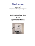
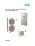
Phoenix
Ultrafiltration Units
User Manual
English
Phoenix Ultrafitration Units
For tips and tricks, support and sharing of your experiences visit
www.support.seccua.com
Page 2
Doc. Rev. 19042012 3.19r2 en
Phoenix Ultrafiltration Units
Table of contents
1. User Information................................................................................................................................................................................. 6
1.1 General........................................................................................................................................................................................ 6
1.2 Scope of services and accessories......................................................................................................................................... 6
1.3 Important information................................................................................................................................................................6
1.4 Contact for service and technical support..............................................................................................................................7
2. Important Safety Instructions........................................................................................................................................................... 8
3. Operating Conditions and System Layout....................................................................................................................................... 9
3.1 Operating data of the systems................................................................................................................................................. 9
3.2 System layout............................................................................................................................................................................. 9
1) General information about pressure shocks........................................................................................................................... 9
2) Filtration performance..............................................................................................................................................................9
3) Typical flux rate...................................................................................................................................................................... 10
4) Hydraulic and electrical connections.................................................................................................................................... 11
a) Connection of individual systems................................................................................................................................... 11
b) Hydraulic connections.................................................................................................................................................... 12
3.3 Electrical connection............................................................................................................................................................... 12
4. System Description.......................................................................................................................................................................... 13
4.1 Dimensions and weight........................................................................................................................................................... 13
1) Control & Filter unit................................................................................................................................................................ 13
2) Assembled units.................................................................................................................................................................... 13
3) Phoenix 4............................................................................................................................................................................... 14
4) Phoenix 7............................................................................................................................................................................... 14
5) Phoenix 10............................................................................................................................................................................. 15
6) Phoenix 20............................................................................................................................................................................. 15
4.2 Internal structure......................................................................................................................................................................15
1) Process and instrumentation diagram (P&ID)....................................................................................................................... 16
2) Denotation of sensors and actuators of the system............................................................................................................. 17
4.3 Electronics................................................................................................................................................................................ 17
1) General...................................................................................................................................................................................17
2) Power supply (single phase)..................................................................................................................................................17
3) Power supply ( 3 phase )....................................................................................................................................................... 17
4) Overview over the electrical connections..............................................................................................................................18
5) Map of connectors in the Connectivity Kit............................................................................................................................ 18
6) Tightness............................................................................................................................................................................... 19
5. Installation......................................................................................................................................................................................... 20
5.1 General instructions.................................................................................................................................................................20
5.2 Electrical checklist...................................................................................................................................................................20
5.3 Checklist casing....................................................................................................................................................................... 20
5.4 Required tools and material....................................................................................................................................................21
5.5 Water connections of the system...........................................................................................................................................21
1) Overview of the water connections....................................................................................................................................... 22
2) Feed line................................................................................................................................................................................ 22
3) Filtrate line..............................................................................................................................................................................23
4) Drain line................................................................................................................................................................................ 23
5) Backwash line........................................................................................................................................................................23
6) Backview of an assembled Phoenix 4...................................................................................................................................24
7) Assembling............................................................................................................................................................................ 24
a) Adjustment of control and filter units; fitting control unit ................................................................................................24
b) Filter unit(s)...................................................................................................................................................................... 25
c) Connect the units............................................................................................................................................................ 25
8) Mounting filter module(s)....................................................................................................................................................... 26
Doc. Rev. 19042012 3.19r2 en
Page 3
Phoenix Ultrafitration Units
5.6 Connecting pumps and cleaning equipment........................................................................................................................ 27
1) Connection of a switched feed pump................................................................................................................................... 27
2) Connection of a frequency controlled feed pump................................................................................................................ 27
3) Connection of dosing pump 2 for feed or chemical dosing during backwash (DO6) .......................................................... 27
4) Connection of the level signal of a feed buffer or filtrate tank.............................................................................................. 27
5) Output of the volumetric flow measured by the system....................................................................................................... 28
6) Read in of a turbidity meter................................................................................................................................................... 28
7) Read in of an alarm signal .................................................................................................................................................... 28
8) Output of an alarm signal ..................................................................................................................................................... 28
9) Output of an alarm signal by using a potential free contact................................................................................................. 28
10) Connection of a switched backwash pump........................................................................................................................29
11) Connection the dosing pump 1 for backwash.................................................................................................................... 29
5.7 Installation of a modem...........................................................................................................................................................29
5.8 Installation of replacement filter modules.............................................................................................................................30
5.9 Rinsing and commissioning....................................................................................................................................................30
1) General...................................................................................................................................................................................30
2) Rinsing of the system............................................................................................................................................................ 30
3) Disinfection of the ultrafiltration system................................................................................................................................ 31
4) Commissioning...................................................................................................................................................................... 31
6. Operation and Programming...........................................................................................................................................................32
6.1 Overview of the operation modes.......................................................................................................................................... 32
6.2 Filtration.................................................................................................................................................................................... 32
1) Filtration length depending on the quality of the raw water..................................................................................................32
2) Removal or reduction of DOC from the raw water................................................................................................................32
3) Sample filtration cycle........................................................................................................................................................... 33
6.3 Cleaning.................................................................................................................................................................................... 33
1) Standard settings of the system............................................................................................................................................33
2) Monitoring of the cleaning efficiency.................................................................................................................................... 33
3) Forward flush......................................................................................................................................................................... 33
4) Backwash (BW)......................................................................................................................................................................33
a) Backwash through downstream pump........................................................................................................................... 34
b) Chemically enhanced backwash (CEBW).......................................................................................................................34
5) Manual chemically enhanced Cleaning-in-Place (CIP)......................................................................................................... 35
a) Required tools and materials.......................................................................................................................................... 35
b) Procedure........................................................................................................................................................................ 36
6.4 Membrane test (Direct Integrity Test, DIT)............................................................................................................................ 41
1) General...................................................................................................................................................................................41
2) Resolution of the integrity test...............................................................................................................................................41
3) Removal values and test sensitivity...................................................................................................................................... 42
4) Test frequency........................................................................................................................................................................42
6.5 Stop mode.................................................................................................................................................................................42
6.6 Disinfection of the system (e.g. after standstill)................................................................................................................... 42
7. Control Panel on the Unit................................................................................................................................................................ 44
7.1 Control panel of the control unit............................................................................................................................................ 44
7.2 Menu structure of the control unit......................................................................................................................................... 45
7.3 Operation.................................................................................................................................................................................. 45
1) Stopping the system..............................................................................................................................................................45
2) Alarm display, error codes..................................................................................................................................................... 46
3) Manual starting of the cleaning............................................................................................................................................. 46
4) Manual starting of the membrane test.................................................................................................................................. 46
8. Programming and PC-Software......................................................................................................................................................47
8.1 Requirements........................................................................................................................................................................... 47
8.2 PC software.............................................................................................................................................................................. 47
1) Installation..............................................................................................................................................................................47
Page 4
Doc. Rev. 19042012 3.19r2 en
Phoenix Ultrafiltration Units
2) Setting up the connection to the control unit........................................................................................................................48
a) Selection of the connection type.................................................................................................................................... 48
b) Troubleshooting connection errors................................................................................................................................. 50
8.3 Operating status display of the software.............................................................................................................................. 51
1) Display................................................................................................................................................................................... 51
2) Sensors displayed:................................................................................................................................................................ 52
3) Actuators displayed:.............................................................................................................................................................. 52
8.4 Setting the parameters in the software................................................................................................................................. 52
1) Programming levels............................................................................................................................................................... 52
2) Saving the settings in the control unit................................................................................................................................... 52
3) Saving the settings to file...................................................................................................................................................... 52
a) Saving the complete parameter set in files:....................................................................................................................52
b) Saving the currently edited parameter set in a file:........................................................................................................ 53
4) Loading the saved settings from a file.................................................................................................................................. 53
5) Setting time and date............................................................................................................................................................ 53
6) Setting filtration......................................................................................................................................................................53
a) Filtration parameters....................................................................................................................................................... 54
b) Configuration of an inlet pump....................................................................................................................................... 55
7) Cleaning................................................................................................................................................................................. 56
a) Backwash during cleaning.............................................................................................................................................. 57
b) Chemical dosing during backwash.................................................................................................................................59
8) Membrane integrity test.........................................................................................................................................................60
9) Alerts...................................................................................................................................................................................... 62
10) Basic settings ("Global")......................................................................................................................................................63
11) Names of operating modes................................................................................................................................................. 65
12) Other strings........................................................................................................................................................................ 65
13) Main menu items................................................................................................................................................................. 66
8.5 Display of the operating data and sensor calibration.......................................................................................................... 66
1) Display of the operating data................................................................................................................................................ 66
2) Calibration of the sensors......................................................................................................................................................67
8.6 Data logger............................................................................................................................................................................... 67
8.7 Firmware and control on the system..................................................................................................................................... 69
1) Saving the settings in a file....................................................................................................................................................69
2) Loading new firmware........................................................................................................................................................... 70
9. Storage of filter modules before and after operation...................................................................................................................72
9.1 General...................................................................................................................................................................................... 72
9.2 Storage of new modules......................................................................................................................................................... 72
9.3 Storage of modules after operation.......................................................................................................................................72
10. Troubleshooting.............................................................................................................................................................................. 74
11. Limited Warranty............................................................................................................................................................................ 75
12. Appendix..........................................................................................................................................................................................77
12.1 Filter modules.........................................................................................................................................................................77
12.2 Additional systems.................................................................................................................................................................77
Doc. Rev. 19042012 3.19r2 en
Page 5
Phoenix Ultrafitration Units
1.
User Information
1.1
General
The Phoenix ultrafiltration installations simultaneously remove turbidity and pathogens from water supplied from surface, spring or
well water sources: Cost-efficiently, without the use of chemicals or radiation.
The fully automated conditioners use extra-rugged, certified ultrafiltration membranes with pore sizes of 20 nanometers or less.
1,000 times smaller than those of a conventional microfilter, the pores in the membrane nearly completely remove viruses, bacteria
and legionella from all types of impure water.
The fully automated, integrated membrane testing, in accordance with approved and proven testing methods, provides the highest
possible level of safety.
Important Note:
This unit is subject to Limited Warranty Conditions, as described in the chapter “Limited Warranty Conditions” in this manual. Do
not operate the unit if you disagree with those Warranty Conditions.
1.2
Scope of services and accessories
According to the accessories installed, the system has the following additional performance characteristics:
Characteristic
Phoenix
with Compressor
Phoenix with
GSM Modem
Filtration, cleaning
√
√
Integrity test
√
√
Connection of GSM modem
√
√
Programming via USB
√
√
√
Programming via modem
Alarm display on the unit
√
√
Alarm signal via potential-free contact
√
√
√
Alarm signal via SMS
Data logger readable via USB
√
√
√
Data logger readable via modem
Control of feed pumps
√
√
Control of dosing pumps (feed and/or backwash)
√
√
Monitoring of peripheral equipment
√
√
1.3
Important information
Please read the guarantee conditions carefully. You can find these in the chapter "Limited Warranty" at the end of this user manual
as well as in the general terms and conditions of the manufacturer . This system left our facilities complete and in functioning condition. Please check the unit immediately upon receipt for completeness and possible shipping damage.
If the system or parts of the system have been damaged during transport, notify the transport company immediately. Transport
damage to the system is not covered by the guarantee.
The guarantee cannot be claimed in the event of damages of the system caused by:
➢
Transport,
➢
Improper use or incorrect installation;
➢
Non-expert and/or insufficient maintenance;
➢
Operation of the system outside the operating conditions described in this user manual; or
➢
Modifications to the system.
Page 6
Doc. Rev. 19042012 3.19r2 en
Phoenix Ultrafiltration Units
Important:
Please be sure that this user manual is always kept close to the system and is always accessible to the operator and that it is
handed over in the event of a change in ownership.
1.4
Contact for service and technical support
Should you require help with your system, please contact your service partner or dealer directly.
Customer support:
Every effort has been made to assure the completeness and readability of these operating instructions. If you have any problems
or questions, we would appreciate you letting us know so that we can improve this user manual.
Seccua GmbH
Krummbachstr. 8
86989 Steingaden
Germany
Tel. +49 (0) 8862 91172-0
Fax. +49 (0) 8862 91172-19
Seccua Americas LLC
15508 W. Bell Rd, Ste. 101-440
Surprise, AZ 85374
United States of America
Tel. +1 623 986-5766
Fax. +1 866 352 8178
Internet: www.seccua.com; Mail: [email protected]
Doc. Rev. 19042012 3.19r2 en
Page 7
Phoenix Ultrafitration Units
2.
Important Safety Instructions
Warning:
In addition to the instructions contained in this manual, be sure to heed all other safety and accident-prevention instructions!
Follow these additional directives for the safe operation of the system:
➢
Read this user manual carefully before the first commissioning.
➢
All installations and/or changes must be carried out by qualified experts.
➢
Install the system exactly as described in the user manual.
➢
Only use the recommended chemicals for cleaning.
➢
Do not connect the system to the power mains if the connecting plug or cable is damaged.
➢
Only authorized service technicians should perform maintenance on this system. For any modifications or repairs, con tact your service partner.
➢
Do not expose any electrical cables to water.
➢
Do not kink the connecting cable. Ensure that it is safely and sufficiently attached.
➢
When performing any repairs, disconnect the system, remove it from the network and let it cool down.
➢
Electrical protective measures in accordance with VDE 0100 must be checked by authorized experts.
➢
Do not use any extension cords in the installation of the system.
➢
The maximum differential pressure (measuring points are in front of and behind the UF-filter / on the filter unit) may not
exceed 2.5 bar/36.26 psi.
➢
Avoid pressure shocks. These can be caused e.g. by shutting off external valves or pumps in the inlet of the system.
➢
Be careful! Solenoid valves can become hot.
Warning:
When dealing with chemicals pay close attention to the relevant instructions and security warnings on the containers! Danger of
chemical burns and poisoning! We urgently recommend that the system be installed by an authorized service partner. Please observe all the relevant regulations at the time of installation!
Warning:
Be extremely cautious when handling chemicals. Follow the manufacturer's instructions in every circumstance!
Never mix chemicals with other cleaning agents! Always use protective gloves and protective glasses while working with the
chemicals.
All cleaning and disinfection chemicals must be NSF 60 certified!
Warning:
Caution: electrical voltage!
The power supply to the system must be interrupted before carrying out work on the control unit or the relay box. Always discon nect the power supply before opening the covers of the control unit or the relay box!
Page 8
Doc. Rev. 19042012 3.19r2 en
Phoenix Ultrafiltration Units
3.
3.1
Operating Conditions and System Layout
Operating data of the systems
Max. operating pressure
5.0 bar (=500 kPa)
Max. operating temperature
40 °C ( 104°F )
Min. operating temperature
4 °C ( 32°F )
Storage temperature
0 °C to +40 °C ( 32°F to 104°F )
pH-range
1 to 13 (during cleaning)
2 to 11 (during operation)
Chlorine tolerance
In regard to free chlorine:
Total loading 200,000 (mg/l)xh,
200 mg/l max. concentration
Max. allowable pressure difference
between inlet – filtrate
0 – 2.5 bar (=250 kPa)
0 – 36.26 psi
Molecular Weight Cutoff MWCO
(g/mol or Dalton)
100,000 – 150,000
Cleaning method
Cleaning and backwashing, either time-inter val controlled, according to a particular time or
through contamination monitoring
Max. operating pressure
5.0 bar (= 500kPa)
72.52 psi
Warning:
Never exceed the maximum operating pressure. Make sure that no water hammer occurs which might exceed the maximum op erating pressure!
Note:
See further details on the performance of each respective system in the appendix.
3.2
1)
System layout
General information about pressure shocks
Rapidly closing valves, piston pumps and vertical pipe layouts can cause damaging pressure shocks. These, in turn, can lead to
fibrous fractures in the membrane, damage to the pipeline network, the membrane itself as well as the seals and additionally can
cause deviations to system dimensions.
For all practical applications of ultrafiltration, liquids are not compressible, all energy is immediately transferred. This energy becomes dynamic, when force acts on it, such as rapidly-closing valves or non speed-regulated pumps.
Impacts and pressure shocks lead to sudden changes in flow speeds. Pressure shocks normally damage the system through rapid
starting, stopping or changes in the direction of flow. Any of these causes can lead to catastrophic faults in the system. Rapidly
closing valves, whether activated manually or automatically, are without question the most frequent cause of pressure shocks in
the application. A valve closing in 1.5 seconds or less (depending upon the size of the valve and the system conditions), can cause
an abrupt break in the flow. A pressure shock (audible wave) caused by a rapidly closing valve can easily amount to five times the
normal system pressure. Therefore, the utilization of calculation programs, which enable comprehensive evaluation of the pressure
and the flow characteristics of the system, are recommended for the pressure evaluation of the system that is to be installed in the
facility. For evaluation, the analysis should be utilized for the "worst case scenario", the normal operation and furthermore for the
pump circulation.
2)
Filtration performance
The filtration performance of the system among other depends on the following parameters:
a) The utilized filter surface area of the system,
b) the flux rate, i.e. the surface load (throughput per filter surface area)
Doc. Rev. 19042012 3.19r2 en
Page 9
Phoenix Ultrafitration Units
System type
Membrane surface area
Long-time surface contamin- Surface area contamination
ation
at peak load
80 – 160 l/(m 2h)
max. 300 l/(m 2h)
Phoenix 4
60 m²
4–8 m3/h ( 18 - 36 gpm )
15 m3/h (66 gpm)
Phoenix 7
120 m²
8–16 m3/h ( 36 – 70 gpm)
30 m3/h (132 gpm)
Phoenix 10
240 m²
16–32 m3/h (70 - 140 gpm)
60 m3/h (263 gpm)
Phoenix 20
360 m²
29-58 m /h (127 - 254 gmp)
108 m3/h (473 gpm)
3)
3
Typical flux rate
The following table shows the applicable flux rate through the unit depending on the degree of contamination of the raw water.
These values are guidelines and the achievable flux rate can differ upwards or downwards. In case of doubt it is recommended to
refer to a reference application or if necessary to operate a pilot system.
Raw water inlet
Properties
Recommended process
Fluxrate, continuous
Well or spring water
Low degree of turbidity
No DOC
<300 µm pre-filtration
Ultrafiltration
120 l/(m2h)
71 gfd
Well or spring water, affected
by surface water
Fluctuating, occasionally occurring turbidity
No DOC
<300 µm pre-filtration
Ultrafiltration
80 - 120 l/(m2h)
47 – 71 gfd
Fluctuating, occasionally occurring turbidity with DOC
<300 µm pre-filtration
Ultrafiltration with CIP*
80 – 100 l/(m2h)
47 – 59 gfd
Surface water or well or spring
water strongly affected by the
surface water
Continuous turbidity and DOC
<300 µm pre-filtration
60 – 80 l/(m2h)
Flocculation
36 – 47 gfd
Ultrafiltration with CIP*
In some cases the utilization of
a media filtration before the UF
is recommended
Swimming pool water
Pathogens and DOC
Hair removal (disk filter)
Flocculation
Activated carbon
Ultrafiltration with CIP*
140 – 160 l/(m2h)
83 – 95 gfd
*CIP: "cleaning in place", automatic cleaning, fixed installation. Either with an acid/base combination, sodium hypochlorite or other
chemicals.
Page 10
Doc. Rev. 19042012 3.19r2 en
Phoenix Ultrafiltration Units
4)
Hydraulic and electrical connections
a)
Connection of individual systems
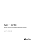
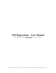
Individually operated Phoenix systems are able to control and monitor peripheral equipment. The following schematics show in
which manner the equipment can be connected.
Diagram 1: A Phoenix system with an inlet pump, a backwash pump and two chemical dosing pumps for automatic
cleaning.
Diagram 2: A Phoenix system with an inlet pump, a dosing pump in the inlet, a backwash pump and chemical dosing
pump for automatic cleaning.
Doc. Rev. 19042012 3.19r2 en
Page 11
Phoenix Ultrafitration Units
b)
Hydraulic connections
Hydraulic connections
Description
Connection
Inlet
Connection of the raw water.
A <300 µm pre-filter should be installed upstream of the
system.
2” Victaulic
Filtrate
Filtrate outlet, supplies pure water.
2” Victaulic
Backwash
This connection is utilized by the pump or membrane re ceptacle during backwashing in order to press filtered,
pure water through the system.
2” Victaulic
At this location there should be 2.5 bar of pressure dur ing backwashing and 0 bar during filtration.
Drain
Rinse water of the system.
2” Victaulic
During pure water rinsing, the rinse water can be lead
into draining canals or the canalization, during chemical
cleaning and the addition of chemicals during filtration
for instance, a neutralization of the rinse water must be
performed.
3.3
Electrical connection
Voltage
Power (max.)
Frequency
120 V
225 W
50/60 Hz
230 V
225 W
50/60 Hz
Note:
Make sure your system is specifically set up for 120 V or 230 V!
Warning:
Electrical shock!
➢
Follow the instructions in this manual!
➢
Failure to do so can cause serious injury or death!
➢
All electrical connections must be compliant with local ordinance and/or DIN/VDE directives!
➢
Do not change the connecting plug or the connecting cable!
➢
Do not use extension cords!
➢
Before opening the cover, always disconnect the system from the power supply (pull the power supply plug)!
Page 12
Doc. Rev. 19042012 3.19r2 en
Phoenix Ultrafiltration Units
4.
4.1
1)
System Description
Dimensions and weight
Control & Filter unit
The systems consist of a control unit and one to six filter units. The system is disassembled for transport, as the filter modules may
not be transported while fitted to the system. The filter modules are packaged separately and enclosed with the system.
Diagram 3: Filter unit (dimensions in mm)
2)
Diagram 4: Control unit (dimensions in mm)
Assembled units
Type
Width (in)
Depth (in)
Height* (in)
Weight** (lb)
Phoenix 04
ca. 51 in
ca. 24 in
ca. 75 in
ca. 300 lb
Phoenix 07
ca. 71 in
ca. 24 in
ca. 75 in
ca. 800 lb
Phoenix 10
ca. 110 in
ca. 24 in
ca. 75 in
ca. 1100 lb
Phoenix 20
ca. 143 in
ca. 24 in
ca. 75 in
ca. 1400 lb
*) The Units are height adjustable.
**) Filters filled with water
Doc. Rev. 19042012 3.19r2 en
Page 13
Phoenix Ultrafitration Units
3)
Phoenix 4
Diagram 5: Dimensions of Phoenix 4 in mm
4)
Phoenix 7
Diagram 6: Dimensions of Phoenix 7 in mm
Page 14
Doc. Rev. 19042012 3.19r2 en
Phoenix Ultrafiltration Units
5)
Phoenix 10
Diagram 7: Dimensions of Phoenix 10 in mm
6)
Phoenix 20
Diagram 8: Dimensions of Phoenix 20 in mm
4.2
Internal structure
The systems are always equipped with one to six filter modules. Having minimum two filter modules has the advantage that the
systems can perform a mutual backwash (one filter module backwashes the other alternating).
The schematic shown below shows the P&ID of the system, whereby the pumps shown in the diagram are not part of the system
and must be installed separately.
Doc. Rev. 19042012 3.19r2 en
Page 15
Phoenix Ultrafitration Units
1)
Process and instrumentation diagram (P&ID)
Diagram 9: Hydraulic schematic with valve arrangement
Collector
Filtrate
Collector
Drain
Distribution rack
Feed
Diagram 10: Back view of control unit with
actuators and sensors
Page 16
Doc. Rev. 19042012 3.19r2 en
Phoenix Ultrafiltration Units
2)
4.3
1)
Denotation of sensors and actuators of the system
P1
Pressure sensor inlet, filter 1
P2
Pressure sensor, filtrate, upstream of V5
L
Compressor
V1
Inlet valve, filter 1
V2
Drain valve, filter 1
V3
Inlet valve, filter 2
V4
Drain valve, filter 2
V5
Filtrate valve
Electronics
General
The systems are delivered with a "Connectivity Kit". The Connectivity Kit offers a variety of electrical connection
possibilities.
Note:
The relays in the Connectivity Kit are designed to handle 16 A during operation. Consider starting currents of pumps!
2)
Power supply (single phase)
The whole system is supplied with power via the Connectivity Kit.
The power cable, through which the Phoenix system is supplied with power, is connected to the following Connectors in the Kit:
Connect to Connectivity Kit
3)
Strip
Pin
Phase 1
X8
1
Neutral wire
X8
4
Ground
X8
5
Power supply ( 3 phase )
In case pumps supplied through 3-phases are being connected to the Connectivity Kit, the kit's power-supply itself needs to be
wired to a 3-phase supply.
Connect to Connectivity Kit
Strip
Pin
X8
1
Phase 2
X8
2
Phase 3
X8
3
Neutral wire
X8
4
Ground
X8
5
Phase 1
Note:
Protection of the system through circuit breakers must be installed outside of the system. If pumps are connected to the Con nectivity Kit through their power supply, it is recommended to use pumps with integrated dry running protection or protect stand ard pumps by a float switch against running dry. Additionally a motor protection circuit breaker should be integrated in between
the Connectivity Kit and the Pump.
Doc. Rev. 19042012 3.19r2 en
Page 17
Phoenix Ultrafitration Units
4)
Overview over the electrical connections
In connection with the Connectivity Kit, the control unit of the system offers the possibility of controlling various peripheral equip ment (such as pumps, dosing pumps, measurement equipment) as well as the evaluation of input signals of external measurement
equipment and the forwarding of alarm signals.
The equipment is connected through connector blocks to the Connectivity Kit of the system. The terminals are opened by pressing
the clamping lever backwards. The stripped cable can then be inserted and releasing the lever closes the terminal, which establishes the connection.
The chapter "Connecting pumps and cleaning equipment" (page 27 ff) describes the installation of pumps, cleaning equipment
and other accessories.
5)
Map of connectors in the Connectivity Kit
Diagram 11: PIN assignment Connectivity Kit (relay box)
Page 18
Doc. Rev. 19042012 3.19r2 en
Phoenix Ultrafiltration Units
6)
Tightness
The minimum protection class of the System:
Unit
Tightness
Notice
Control box
IP 54
Valid if all connections are done and the
USB plug is closed.
Connectivity Kit
IP 54
Valid if all connections are done and the
USB plug is closed.
Plugs and harness
IP 67
Valid if all connections are done and the
USB plug is closed.
Please ensure that all PG screws, which have not been assigned, are covered with a corresponding blind plug.
Doc. Rev. 19042012 3.19r2 en
Page 19
Phoenix Ultrafitration Units
5.
Installation
5.1
General instructions
Ensure that your shipment is complete and undamaged.
Note:
If your delivery is damaged or incomplete, please contact our service desk immediately.
5.2
Electrical checklist
Please make sure that the available electrical supply (power supply cable and socket) corresponds to the requirements of the sys tem.
To protect the system, a fuse has been installed in the inside of the control unit (6A, 250W).
After wall-mounting of the control unit, connect the control unit of the system to the power supply with the enclosed power cable.
Warning:
All electrical connections must be compliant with local ordinance and/or DIN/VDE directives!
Warning:
Caution: electrical voltage!
The power supply to the system must be interrupted before carrying out work on the control unit or the relay box. Always discon nect the power supply before opening the cover!
Warning:
Electrical shock!
➢
Follow the instructions in this manual! Failure to do so can cause serious injury or death!
➢
Do not change the connecting plug or the connecting cable!
➢
Do not use extension cords!
➢
Before opening the cover, always disconnect the system from the power supply (pull the plug)!
5.3
Checklist casing
The casing of the Phoenix system commands following fittings:
Width (inch)
Nominal diameter (outward)
Feed
2" Victaulic
60,3 mm
Filtrate
2" Victaulic
60,3 mm
Drain
2" Victaulic
60,3 mm
Note:
Never trim the Pipe ends. Use the flexible Victaulic couplings to
connect the Phoenix to your system! This way the system is con nected tightly and height tolerances are leveled out.
Note:
The system has been designed for a maximum water temperature of 40°C/104°F. Additionally, the temperature of the water in the
inlet should not drop below 4°C/39°F..
Note:
To ensure smooth filtration operation and in order to prevent membrane damage due to rough particles, a pre-filter (max. 300 μm)
must be installed upstream of the system!
Page 20
Doc. Rev. 19042012 3.19r2 en
Phoenix Ultrafiltration Units
5.4
Required tools and material
The following tools and materials are required for wall- and in-line mounting:
➢
Wrench set
➢
Screwdriver set
➢
Ratchet set
➢
Pipe wrench
➢
Torque Ratchet 5Nm
➢
Measuring tape
➢
Cleaning equipment (pump, bucket; 60 l tank; hoses)
➢
Chlorine bleach (13%)
➢
Computer or notebook with the current control software and a USB cable,
➢
Teflon tape or equivalent degreased sealing agent certified for use with drinking water.
Warning:
Please observe all the relevant regulations for the installation!
The pressure in the system must not exceed 5.0 bar/73 psi. If necessary, please install a pressure reducing valve to reduce the
water pressure upstream of the system.
Note:
We recommend that the system be installed and commissioned by an authorized service partner.
Mounting instructions:
Please check following points before mounting the device:
➢
Are all the necessary water connections available (feed, filtrate, drain water)?
➢
Make sure there is a working floor drain installed close to the system to take up spilled water during assembly/disassembly.
➢
Is the required electrical connection available (110 V AC, 230 V AC)?
➢
Check if the floor at the point of installation carries the weight of the system (see chapter 4.1 “Dimensions and weight“).
➢
Is there sufficient space on the front side of the system to allow easy operation of the control unit and carrying out of servi cing and maintenance?
➢
Make sure there is enough space available on the left and right of the system to be able to connect the feed and drain lines.
5.5
Water connections of the system
Note:
We generally recommend the installation of a shut-off option or a stop valve in the inlet of the system, in the rinse water and in the
filtrate line. This simplifies later maintenance and cleaning work.
Doc. Rev. 19042012 3.19r2 en
Page 21
Phoenix Ultrafitration Units
1)
Overview of the water connections
Cleaning attachment
Backwash
Filtrate
Drain
Feed
Cleaning attachment
Diagram 12: Overview of the connections of the systems
Back view Phoenix 4 (control unit is on the right)
The following picture shows the hydraulic connections configured with feed pump, backwash pump and chemical cleaning.
Filtrate
Feedpump
Backwashwater
Dosing unit
Feed
Drain
Neutralisation
Chemical cleaning Chemical cleaning
Dosingunit 1
Dosingunit 2
Diagram 13: Hydraulic connections with back-flow preventers
Notice:
The scheme does not show all required shut off devices. The scheme shows the installation situations of the back-flow preventer
in the water supply. Back-flow preventer always have to be installed horizontal to avoid water-hammer.
2)
Feed line
The system has been designed for a maximum water temperature of 40 °C (104°F). Additionally, the temperature of the water in the
inlet should not drop below 4 °C (39 °F). A strainer must be installed for pre-filtration with a cut-off of 300 μm.
It is also strongly recommended to install a check-valve into the feed-line of the unit to prevent backward flow which could occur
e.g. in times of standstill of the feed-pump. This can also improve the backwash performance in some cases.
Page 22
Doc. Rev. 19042012 3.19r2 en
Phoenix Ultrafiltration Units
Warning:
Even at maximum filtrate performance, the pressure difference between the inlet and filtrate side may not exceed 2.5 bar (36 psi).
The maximum operating pressure in the feed line (dead head) must not exceed 5 bar (72 psi)
3)
Filtrate line
Note:
It must be ensured that the filtrate can be discharged downstream of the system in case needed. An operating pressure of
between 0.5 and 2.5 bar (7.2 psi – 36.3 psi) must be provided for filtration. A sampling valve must be mounted right downstream
of the installation!
It is also strongly recommended to install a check-valve into the filtrate-line of the unit to prevent backward flow which could occur
e.g. in times of standstill of the feed-pump in case of potential back-pressure on the filtrate line.
4)
Drain line
The drain line is required in order to discharge the water during cleaning of the unit.
Please ensure that the nominal size of the drain line should correspond to the feed line pressure and the type of system. When
routing the drain line, it must be ensured that no back flow of any time can form. Therefore, route the drain line without any unne cessary bends and use adequately dimensioned pipe (at least DN 80).
Note:
An open separation must be provided between the system drain and the drain line in order to prevent re-contamination of the
system due to drain water → free drain, in accordance with DIN 1988, Part 4 (Design Classification A, as per European Standard
EN1717) or similar regional plumbing codes.
Important:
Should the drain-line be installed so it rises above the upper edges of the unit, a permanent counter pressure builds up in the
unit's drain-line. This counter-pressure is not relevant during cleaning or filtration. Nevertheless such counter-pressure has to be
considered during automated integrity testing, and the test-pressure p test has to be increased by the additional counter-pressure.
5)
Backwash line
The backwash-line is referred to as the line, with which the system is backwashed against the direction of filtration. Pure water
(=filtrate) on the filtrate side is pressed back through the membranes. Filtered water from the overhead tank or from the supply net work downstream of the ultrafiltration system is used for backwashing and can be operated either with its own dedicated pump or
in the case of a sufficient water quantity and sufficiently high network pressure, can be operated directly from the supply network.
Important:
Please make sure that the backwash pump of a Phoenix system delivers at least:
13.8 m3/h (60 gpm) for a Phoenix 4 and Phoenix 7,
28 m3/h (120 gpm) for a Phoenix 10
and 42 m3/h (180 gpm) for a Phoenix 20.
The pressure the pump has to deliver ranges from 2.5 bar (36psi) to 5 bar (72psi) depending on the worst-case grade of mem brane fouling.
Important:
If an external pump for backwashing is used a check valve has to be installed at the backwash line to prevent loss of water during filtration.
Doc. Rev. 19042012 3.19r2 en
Page 23
Phoenix Ultrafitration Units
6)
Backview of an assembled Phoenix 4
Diagram 14: Backview of a Phoenix 4 system
Part
Part-Nr.
Description
B
10271
Divider raw water
C
10269
Collector drain water
D
10270
Collector filtrate/permeate
E
10248
Dummy plug
F
10241
Victaulic-Hitch
G
Adjustable feet
K
Coupling filter module
L
10223
Extension piece
M
10372 (Sensor with Coupling)
2 Stk. 10397 (Coupling)
Coupling Feed raw water with flowsensor
O
10393 (Stopper)
10394 (Ball valve)
10395 (Hitch)
10396 (Dummy plug)
Stopper and attachment for cleaning.
(Hitch and ball valve)
7)
Assembling
a)
Adjustment of control and filter units; fitting control unit
1.
Screw the adjustable feet into the steel chassis.
2.
Put the control and the filter unit(s) into the provided place. Take care to observe the following distances.
3.
Position the steel racks in equal distance from each other (96 mm. 3.8 inch)
4.
The feed line has to run into the flow sensor straight, with no disturbances that might cause turbulence, for at least the
distance according to EN ISO 5167-1 as shown in the graphs below (DN=50 mm)
Page 24
Doc. Rev. 19042012 3.19r2 en
Phoenix Ultrafiltration Units
5.
Level the Steel chassis using a water scale.
6.
Mark the positions of the steel chassis on the floor.
7.
Pull the control unit forward, so you can assemble it.
a)
Insert the drain water collector (C) first.
b)
Fit the gasket onto the electric connectors of V2 and V4 and connect them to the wire harness. Tighten the screws
of the plugs.
c)
Insert the Filtrate collector (D). The filtrate outlet can be turned to either the left or the right-hand side. The filtrate
exits the unit through the lower pipe – the one with the valve.
d)
Connect the Pressure sensor P2 to the according plug on the wire harness.
e)
Connect the valve V5 to the the according plug on the wire harness.
f)
Insert the feed header (B). The feed header can be turned to either the left or the right-hand side. The feed water
enters the unit through the upper pipe – the one with the valve.
g)
Fit the gasket onto the electric connectors of V1 and V3 and connect them to the wire harness. Tighten the screws
of the plugs.
h)
Connect the Pressure sensor P1 to the according plug on the wire harness.
i)
Put the cable for the flow meter along the feed header through the orifice in the chassis.
8.
Wire the power supply after you moved the control unit back into place.
9.
Wire the antenna cable and the CAN bus cable, if existing.
10. Use silicon grease (no organic grease!) for greasing up the ends of the connectors, so the gaskets of the victaulic coup lings slide on easily.
b)
Filter unit(s)
1.
Pull the filtration unit forward, so you can assemble it.
2.
Put the collectors and headers (T-pieces, part K and L) into the chassis..
3.
Put in the feed-line holding the flow-sensor. There is an arrow on the sensor that has to direct in the direction of flow.
Make sure to mount the sensor the right way.
4.
Use silicon grease (no organic grease!) for greasing up the ends of the connectors, so the gaskets of the victaulic coup ling slide on easily.
5.
Put the rubber gaskets of the Victaulic couplings onto the pipe-endings.
6.
Move the steel chassis of the filter unit back into place, connect the flow-sensor-cable and tighten the plug.
7.
Repeat the Steps 1. to 6. to connect all other Filter units.
8.
If using a external backwash pump, please connect the backwash-water inlet to the extension pieces (L) “Backwash”.
Important!
Don´t forget to put a backflow preventer between the Phoenix system and the backwash pump, as close as possible to the
Phoenix system.
c)
Connect the units
1.
Put the rubber gaskets onto the pipe-endings. ( see Diagram 15 )
Doc. Rev. 19042012 3.19r2 en
Page 25
Phoenix Ultrafitration Units
Diagram 15: Section drawing of a Victaulic hitch including rubber gasket
( black)
2.
Put two half shells around the rubber gasket, shown in the picture. Fix the half shells with the included screws.
3.
Install the dummy plugs and the cleaning connectors by using Victaulic couplings as well.
4.
Connect the Phoenix to your piping system using victaulic couplings.
Important!
Make sure to remove all debris and dirt from inside the pipes leading towards and away from the unit. Those might cause severe
fiber damage or re-contamination in the filtrate water.
Note:
Only use the Victaulic hitches to combine the Phoenix units and fit it to your system. Don`t cut any pipes!
8)
Mounting filter module(s)
1.
Put the filter-module on the steel chassis and attach it to the couplings of the headers and collectors using the supplied
Victaulic couplings.
2.
Close the screws of the couplings hand-tight.
3.
Repeat Steps 1. and 2. to connect all the modules to the Phoenix system.
4.
Tighten all couplings of the system now, using a ratchet wrench.
5.
Check the torque of the clamps, holding the module's endcaps. The torque must be 40Nm.
Note:
Inspect the torque of the module's endcaps' clamps every 3 months. Do this inspection while the system is not pressurized!
Page 26
Doc. Rev. 19042012 3.19r2 en
Phoenix Ultrafiltration Units
5.6
Connecting pumps and cleaning equipment
Pumps and cleaning equipment can only be connected to a Connectivity Kit. If the system is not fitted with this kit, please skip this
chapter. The Connectivity Kit itself is connected to the power mains following connection of all peripheral equipment, as described
in chapter 5, "Map of connectors in the Connectivity Kit".
1)
Connection of a switched feed pump
Connection Connectivity Kit
Connector
block
Pin
Phase 3 (if present)
X3
11
Phase 2 (if present)
X3
12
Phase 1
X3
13
Ground
X3
9
Neutral
X3
10
The power supply of the pump is performed via the Connectivity Kit. Max. current per phase 16A. In order to supply a 3-phase
switched feed-pump through the Connectivity Kit, the Kit must be connected to a 3-phase power-supply itself.
2)
Connection of a frequency controlled feed pump
Connection Connectivity Kit
Connector
block
Pin
Control signal 4-20 mA
X5
12
Ground for analog signal
X5
6
If existing, the feed-pump's variable speed drive can be supplied with a 4-20mA signal, which can be programmed to either softstart the system, run it at a fixed flow or match the filling-level of a feed-buffer-tank (low level, low speed and vice versa).
3)
Connection of dosing pump 2 for feed or chemical dosing during backwash (DO6)
Connection Connectivity Kit
Connector
block
Pin
Grounding
X3
3
Neutral
X3
4
Phase 1
X3
5
This digital port is used to supply power (single phase, max. 16A) to a dosing pump, which can be either used to dose a second
chemical during the sequence of a chemically enhanced backwash, or to dose a chemical into the feed of the system during filtration (function is determined in the software-settings).
4)
Connection of the level signal of a feed buffer or filtrate tank
Connection Connectivity Kit
Connector
block
Pin
Input signal 4-20 mA
X5
9
Ground for analog signal
X5
6
Regulation of the inlet pump according to fill height (high speed at high fill height, low speed at low fill height). During a for ward-flush of the system, the incoming signal of the feed-buffer-tank is over-ridden and the control always puts out 20 mA to the
feed-pump (if connected to the Phoenix's 4-20 mA signal).
Alternatively, once a level meter that monitors a filtrate tank is connected to these connectors, filtration can be stopped when pro -
Doc. Rev. 19042012 3.19r2 en
Page 27
Phoenix Ultrafitration Units
grammable levels in the filtrate tank are reached or cleaning cycles are only started if enough water for backwash is still available.
5)
Output of the volumetric flow measured by the system
Connection Connectivity Kit
Connector
block
Pin
Output signal 4-20 mA
X5
13
Ground for analog signal
X5
14
Signal can be used e.g. for the control of a filtrate-aeration-system, a residual chlorine-dosing system or similar.
6)
Read in of a turbidity meter
Connection Connectivity Kit
Connector
block
Pin
Input signal 4-20 mA
X5
2
Supply voltage 12 V
X5
1
The read-in values are saved in the data logger and can be used to trigger a direct integrity test.
7)
Read in of an alarm signal
Connection Connectivity Kit
Connector
block
Pin
Supply voltage 12 V
X5
7
Input 0 V / 12 V
X5
8
GND
X5
6
Input closed = measured 0V = no alert; Input open = measured 7 to 12V = alert (measured between X5/Pin 8 & X5/Pin6)
The control monitors external cold contacts using a 12 V potential between X5.8 and X5.6. If the potential between X5.8 and X5.6
is 0V, the controller interprets that as “no error”, if the potential rises to 7 to 12 V the controller interprets that as “external error”.
8)
Output of an alarm signal
Connection Connectivity Kit
Connector
block
Pin
Input voltage 12 V
X5
15
Ground alarm
X5
16
12VDC = No Alarm; 0V = Alarm
The Phoenix can signal an alert by putting out a 12 V signal between X5.15 and X5.16.
9)
Output of an alarm signal by using a potential free contact
Connection Connectivity Kit
Connector
block
Pin
Potential free contact
X6
1
Potential free contact
X6
2
This contact may be used as a Enable-/Disable contact to drive a frequency converter for example. The contact is closed during
normal operation of the system and opened upon an error.
Page 28
Doc. Rev. 19042012 3.19r2 en
Phoenix Ultrafiltration Units
10)
Connection of a switched backwash pump
Connection Connectivity Kit
11)
Connector
block
Pin
Grounding
X9
1
Neutral
X9
2
Phase 3 (if present)
X9
3
Phase 2 (if present)
X9
4
Phase 1
X9
5
Connection the dosing pump 1 for backwash
Connection Connectivity Kit
Connector
block
Pin
Grounding
X3
14
Neutral
X3
15
Phase 1
X3
16
This dosing pump is the first pump that is addressed during a chemically enhanced backwash. It can also be used as the only
pump being used during such a cleaning sequence, e.g. in case only NaOCl is used to enhanced every X th backwash.
5.7
Installation of a modem
Note:
Ensure that the power supply to the control unit has been disconnected and you are grounded in order to prevent damaging the
modem and the control unit due to electrostatic charges. Please use ESD safety precautions.
Perform the following to install an internal modem in the control unit:
1.
Remove the plastic cover strip on the left and right-hand side of the control unit.
2.
Open the visible screws that are located at the top (the upper and lower), fold the cover of the control unit upwards and
fix it in place to prevent it from closing on its own or falling down. Be careful to not pull out the flat band cable from the
operating panel.
3.
Insert the SIM card into the modem.
4.
Loosen the screws on the corresponding spacer on the printed circuit board.
5.
Connect the thin antenna cable on the side of circuit board, on which the connector for the connection to the main board
is located (small connector).
6.
Insert the modem in the circuit board and secure it with the screws of the spacers (see diagram below).
Doc. Rev. 19042012 3.19r2 en
Page 29
Phoenix Ultrafitration Units
Antenna
Antenna
Antenna
Antenna
Diagram 16: Opened control unit with fitted modem module and SIM card.
The inserted antenna cable is also visible.
7.
Insert the antenna cable to the antenna connector on the outside of the housing.
8.
Reconnect the control unit and secure the screws of the cover. While securing ensure the correct seating of the seal.
9.
Now configure the modem as described in chapter “Configuring an internal modem” under 8.2 (Seite 49).
Note:
If the SIM card has been installed in the control unit, the control unit may not be started more than three times without entering
the correct PIN number in the PC software or else the SIM card will be blocked. This card must then be inserted in a cellular
phone and re-enabled by means of entering the available PUK number (which you will receive from your service provider).
First you should configure the PIN number, as described in chapter “Configuring an internal modem” under 8.2 (Seite 49).
5.8
Installation of replacement filter modules
Please follow the description as can be found on page 26 ff.
5.9
1)
Rinsing and commissioning
General
Before commissioning of the system please first ensure that all impurities are removed from the connection lines in order to avoid
damage to the membrane and to guarantee a maximum filtrate quality.
Note:
It must be ensured that the pipeline network between the system and the extraction points is disinfected after installation.
All systems are disinfected and preserved before they leave our factory. However, it is possible that re-contamination occurs at the
installation site! Additionally, the filter modules are delivered with natural food preservative solution. This must be rinsed out before
commissioning of the system.
Note:
Please ensure that no metal, plastic particles or oil residues remain in the connection line, as these can damage the membrane
capillaries. Any deposits and debris must be removed before connection to the system!
2)
Rinsing of the system
After the removal of debris, especially plastic and metal particles from the feed line, proceed as follows to de-aerate the system :
1.
Connect the system to feed-, filtrate and drain lines as described above.
2.
Turn on the power supply of the system (connect the mains plug).
Page 30
Doc. Rev. 19042012 3.19r2 en
Phoenix Ultrafiltration Units
3.
If necessary, program the control unit according to the instructions (see page 32 ff "Operation and Programming").
Note:
Please ensure that the filtrate is discharged during commissioning and the rinsing procedure and that it does not reach the over head tank or the supply mains.
4.
Start the filtration mode by pressing the "Start" button.
5.
Let the system continue to operate in the filtration mode until the entire preservative has been rinsed out (typically this
takes around 20 minutes or a water amount as specified below:
6.
3)
Type
Required water amount for rinsing
Phoenix 4
5 m³ (1135 gal )
Phoenix 7
10 m³ (2270 gal )
Phoenix 10
20 m³ (4540 gal )
Phoenix 20
30 m³ (6810 gal )
Stop the system by pressing the "Stop" button.
Disinfection of the ultrafiltration system
The entire system must be disinfected after the rinsing has been completed.
Warning:
Make sure to take the necessary pre-caution measures when handling cleaning chemicals, such as chlorine. Always wear safety
goggles and protective gloves and clothing. Follow the safety datasheet as supplied with the cleaning chemicals.
Procedure:
1.
It is recommended to disinfect the Ultrafiltration system after installation. Use chlorinated water which you circulate
through the unit from the feed to the filtrate side of the system at a concentration of free chlorine of 20ppm.
2.
If required, also disinfect downstream installation components (e.g. filtrate tanks) with the solution.
Warning!
Make sure the desinfection-solution does not get into the drinking water network incidentally.
3.
Stop the system and let the system soak in the chlorine solution for at least 30 minutes.
4.
Restart the filtration with fresh water and keep discharging the water in the filtrate of the system until no chlorine can be
detected any more.
5.
The disinfection is now complete.
6.
You can now put the unit back into operation and direct the filtrate into the line network.
Note:
All cleaning and disinfection chemicals must be NSF 60 certified!
4)
Commissioning
To finalize the commissioning you have to start the PC software and calibrate the pressure sensors and adapt the cleaning options
if necessary.
Doc. Rev. 19042012 3.19r2 en
Page 31
Phoenix Ultrafitration Units
6.
Operation and Programming
6.1
Overview of the operation modes
The operation of the Phoenix ultrafiltration system is sub-divided into various operation modes.
A defined sequence of different operation modes is referred to as a filtration cycle. After a certain number of passes of the filtration
cycle a chemically supported backwash can be performed.
In the case of water with a varying degree of turbidity (e.g. karst water) the system is operated depending on the degree of mem brane fouling in order to enable an optimal adaptation of the operation of the ultrafiltration system to the quality of the feed water.
Name
Description
De-aeration
Removal of air from the system before filtration
Filtration
Filtration of water by the membrane filter
Backwashing (internal or through pump or pressurized tank)
Filters are rinsed against filtration direction
Optional: dosing of a cleaning chemical #1
Optionally, if cleaning equipment installed
Optional: Clean-water backwash
Flushing of the membrane filter with filtered water after chem ical dosing #1.
Optional: dosing of a cleaning chemical #2
Optionally, if cleaning equipment installed
Optional: Clean-water backwash
Flushing of the membrane filter with filtered water after chem ical dosing #2.
Rinsing
Forward Flush with raw water
Direct Integrity Test
Automatic examination of the membrane filter for damage
6.2
Filtration
The actual ultrafiltration takes place in the operating mode “Filtration“. Water is forced from the inlet side (feed) into the membrane
capillaries and through the membrane fiber walls onto the filtrate side (filtrate).
1)
Filtration length depending on the quality of the raw water
Parameter
Unit
Default setting
Min. Filtration Duration
Minutes
20
Max. Filtration Duration
Minutes
60
Automatic start of a cleaning cycle when membrane perform ance drops to (compared to new membranes)
%
90
Using those standard setting, the system will filter no shorter than 20 minutes and not longer than 60 minutes before starting a
cleaning cycle. In between those boundaries, the system will trigger a cleaning cycle as soon as the membrane fouling drops the
system performance to 90% compared to new membranes.
Note:
Please note that the above mentioned information is only intended as an adjustment guideline. The actual applicable settings de pend exclusively on the quality of the raw water and can considerably deviate from the table shown above.
2)
Removal or reduction of DOC from the raw water
DOC (dissolved organic carbon) describes the organic components dissolved in the raw water. These occur among others when
the raw water originates from wetlands, forests or fertile catchment areas. Additionally, streams, rivers and similar bodies of water
contain DOC.
When DOC is present in the raw water, the fouling layer, which forms during filtration on the membrane, cannot be removed with
pure water backwashes alone and instead alkaline cleaning agents must be used.
Page 32
Doc. Rev. 19042012 3.19r2 en
Phoenix Ultrafiltration Units
3)
Sample filtration cycle
1.
Filtration (pure water generation)
2.
Forward flush
3.
Backwash F1
4.
Backwash F2
5.
Forward flush
6.3
Cleaning
The set-up of the various cleaning possibilities and backwashing times depend on the quality of the raw water.
The more turbid the water, the more frequently the membranes must be cleaned. If organic carbon compounds (often referred to as
TOC or DOC in the analysis) are present in the raw water, it is recommended to either remove these substances upstream the ul trafiltration or by regular cleaning of the system (either manually or automatically) with the utilization of cleaning chemicals.
Note:
You can find guiding values for setting of the cleaning parameters listed below. However, please note that the optimal settings for
your particular system can deviate from these specifications!
1)
Standard settings of the system
The Phoenix system is set to the following default factory settings:
1.
2.
2)
Triggering of a cleaning cycle
a)
in the case of a drop in filter performance (the ratio of flow to required pressure) to 90% of the initial performance
and
b)
at least every 60 minutes, but
c)
not more often than every 20 minutes.
A cleaning cycle consist of:
a)
Forward flush (10 seconds),
b)
followed by internal backwashing (60 seconds per module),
c)
followed by a forward flush (10 seconds).
Monitoring of the cleaning efficiency
Following the end of a cleaning cycle the system switches back to filtration and performs an immediate evaluation of the degree of
fouling of the filters in order to monitor the cleaning efficiency of the system. If this rate of efficiency lies below the required, to be
set percentage ("Minimum Q/dp after cleaning", default 80%), the control unit will automatically trigger an error message (Fi08).
3)
Forward flush
During a forward flush, the membrane fibers are flushed alongside the inside of the membrane, from the feed to the drain side of
the filter. No water flow takes place through the membrane. The forward flush takes off fouling layers out of the membrane fibers. It
should be performed at a high flow speed and have a duration of approx. 10 seconds.
It has to be assured that the flow during a forward flush of a unit can minimum 50 Liters per minute or 13 gpm. In case that filtration takes place at a low flow rate, it might be necessary to ramp up the speed of the feed-pump during a forward flush in order to
achieve such high flow. In such case the feed-pump of the system needs to be equipped with a variable speed-drive which is connected to the 4-20 mA feed-pump-signal of the system. The system then ramps up the feed-pump signal to 20 mA during a for ward flush.
4)
Backwash (BW)
During backwash the filtration flow is reversed and filtered water is pressed from the filtrate side through the membrane to the inlet
side (feed) from where it is routed into the drain.
There are several possibilities of backwashing:
1.
Internal backwash of filter units. The filters backwash themselves one after the other, whereby one element produces the
water to backwash the other one. Internal backwashes only work with clean feed-water.
2.
The filter modules are backwashed by a pump, which is connected downstream of the system and draws water from a
filtrate tank (a Connectivity Kit is required for this operation).
3.
The unit is backwashed from a permanently pressurized line (e.g. a supplies main or a pressurized tank). In such case a
normally closed solenoid valve has to be installed between the pressurized line and the unit, which is connected to the
Doc. Rev. 19042012 3.19r2 en
Page 33
Phoenix Ultrafitration Units
system's Connectivity Kit and controlled like a backwash-pump.
a)
Backwash through downstream pump
During a backwash through a pump, the modules of a system are backwashed separately in sequence. The flow that has to be delivered by the backwash-pump has to achieve 14 m3/h (60 gpm) for a Phoenix 4 and 7, 28 m3/h for a Phoenix 10 (120 gpm) and 42
m3/h (180 gpm) for a Phoenix 20. The pressure loss that has to be overcome can be seen from below diagram. It is measured at
the system's backwash-port.
Diagram 17: Required flow-pressure during a backwash, to be delivered by backwash pump at unit, depending on membrane foul ing.
Note:
Backwash pumps must be connected to the system's Connectivity Kit. They can only be switched on and off.
b)
Chemically enhanced backwash (CEBW)
During the chemical cleaning of the system, the filter modules are rinsed and cleaned with a solution of pure water and cleaning
chemicals. The rinse water contains a high or low pH value, often with further added cleaning agents, which may not be released
into the drain water without neutralization.
Page 34
Doc. Rev. 19042012 3.19r2 en
Phoenix Ultrafiltration Units
Diagam 18: Flow chart of filtration and cleaning
5)
Manual chemically enhanced Cleaning-in-Place (CIP)
A chemically enhanced Cleaning-in Place is typically required one up to four times per year. Depending on the water quality it may
be required more often in some cases.
a)
Required tools and materials
•
Safety glasses
•
Safety clothes and gloves
•
Chemical resistant pump, up to
•
14 m3/h (61 gpm) at max. 3 bar (43.5 psi) for Phoenix 4 and Phoenix 7
•
28 m3/h (122 gpm) at max. 3 bar (43.5 psi) for Phoenix 10
•
42 m3/h (183 gpm) at max. 5 bar (73 psi) for Phoenix 20
•
Chemical resistant tank with top inlet and bottom outlet (PE or similar, 100 Liter, 26.3 Usgal)
•
Flexible hose, chemical resistant (PE in-liner), safe and chemical resistant hose-couplings
•
Cleaning chemicals
Note:
Please make sure all used cleaning chemicals match the required drinking water standards (e.g. NSF 60 in the USA).
Doc. Rev. 19042012 3.19r2 en
Page 35
Phoenix Ultrafitration Units
Warning!
Please read carefully all the material and safety datasheets supplied with the cleaning chemicals you are using. Always use safety
goggles and protective clothing when handling chemicals.
Warning!
Never mix NaOCl (Bleach, Hypochlorite) with acids. Lethal chlorine gas will be generated!
b)
Procedure
Making cleaning solution
1.
Fill the tank intended to use for cleaning with around 60 liters of filtered water (approx 15 Usgal).
2.
Add cleaning chemicals, choose chemicals as required.
3.
Mix cleaning chemicals well and measure pH of your cleaning solution with a pH-meter!
Water Source
Cleaning Agent
Important Criteria
Turbidity
Water
Flow during backwash per module
>30 l/min (>7.8 gpm)
DOC
Caustic / Caustic & Surfactants
pH > 13
Bacteria, Algae
Peroxide, Sodiumhypochlorite
H2O2: 50 mg/l
NaOCl: 20 mg/l (free chlorine)
Mn, Fe
Acid & oxidizing agents
Peracidic acid & Peroxide
Hardness
Acid
PH < 1.5
Important parameters for cleaning
1.
Right cleaning agent applied.
2.
Temperature (as high as possible, but never higher than 40°C / 104 F).
3.
Concentration (as strong as possible, but obey maximal tolerances of system and used piping material).
4.
Soaking time (always > 30 minutes, if possible over-night).
5.
Flux rate (obey max. transmembrane pressure and max. operating pressure).
Diagram 19: Cleaning connectors of a Phoenix system (1 to 4)
Page 36
Doc. Rev. 19042012 3.19r2 en
Phoenix Ultrafiltration Units
Stop filtration and drain the unit
1.
Switch UF system into stop-mode by pushing the “Pause”-key.
2.
Close external feed and filtrate valves up- and downstream of the unit (if installed).
3.
De-pressurize feed and filtrate line up- and downstream of the system. There must be no pressure on the feed nor on the
filtrate-port.
4.
Connect your PC to the control via USB.
5.
Verify on the main screen of the PC Software, that P1 (inlet pressure) shows P1= 0 bar.
Warning!
Make sure that no cleaning chemicals can reach into the drinking water supply!
6.
Verify the settings of the valves in the software in stop mode:
Valve
Description
Display in soft- Effect if pressure in feed line is higher than in the
ware
unit, normal direction of flow
Feed valve 1
V1
V1: dark green
Closed (powered)
Drain valve 1
V2
V2: dark green
Closed (un-powered)
Feed valve 2
V3
V3: dark green
Closed (powered)
Drain valve 2
V4
V4: dark green
Closed (un-powered)
Filtrate valve
V5
V5: dark green
Closed (powered)
7.
Now change the settings of the valves according to the table below to drain the unit:
Valve
Description
Display in soft- Effect if pressure in unit is higher than in the
ware
feed line, direction of flow from unit to the valves
Feed valve 1
V1
V1: green
Closed (un-powered)
Drain valve 1
V2
V2: green
Open (powered)
Feed valve 2
V3
V3: green
Closed (un-powered)
Drain valve 2
V4
V4: green
Open (powered)
Filtrate valve
V5
V5: dark green
Closed (powered)
8.
Drain the UF system by connecting hoses to 1 and 3 and opening all cleaning connectors' globe-valves.
Important!
Make sure the feed line to the system is un-pressurized and there is no back-pressure on the filtrate line before you proceed!
Usually there are globe valves installed upstream and downstream of the system that need to be closed.
Filling, circulating and soaking with cleaning chemicals
1.
Circulate cleaning solution from the feed unit (1) to the drain-side (2) of the unit:
A)
Connect the pressurized side of the pump to the cleaning port 1 of the unit and connect the drain-side of the unit
(2) looping back to the tank holding cleaning solution. In case cleaning agents containing detergents are used,
make sure no foam can build up during re-circulation.
B)
Verify the valves settings for circulation of cleaning solution through module #1:
Doc. Rev. 19042012 3.19r2 en
Page 37
Phoenix Ultrafitration Units
Valve
Description
Display in soft- Effect if pressure in unit is higher than feed and
ware
filtrate pressure, i.e. direction of flow from module to the valves
Feed valve 1
V1
V1: dark green
Open (powered)
Drain valve 1
V2
V2: dark green
Closed (un-powered)
Feed valve 2
V3
V3: dark green
Closed (powered)
Drain valve 2
V4
V4: dark green
Closed (un-powered)
Filtrate valve
V5
V5: dark green
Closed (powered)
C)
Start circulation by opening globe valves 1 and 2, circulate through module 1 for about 5 minutes.
D)
Stop circulation.
E)
Verify the valve setting for circulation of cleaning solution though module #2:
Valve
Description
Display in soft- Effect when pressue in side #2 of the system is
ware
higher than feed-pressure.
Feedv alve 1
V1
V1: dark green
Closed (powered)
Drain valve 1
V2
V2: dark green
Closed (un-powered)
Feed valve 2
V3
V3: dark green
Open (powered)
Drain valve 2
V4
V4: dark green
Closed (un-powered)
Filtrate valve
V5
V5: dark green
Closed (powered)
2.
F)
Connect cleaning equipment to port #3 (pressurized side of the cleaning pump) and port #4 (loop back to cleaning
tank).
G)
Start circulation, circulate through module #2 for about 5 minutes.
H)
Stop circulation.
I)
The cleaning solution is now left in the unit to soak for at least 30 minutes.
J)
Make up new cleaning solution.
K)
Repeat step 1. until the water circulated is clear.
Circulation of cleaning solution through the membrane (backwashing, not Phoenix 4):
A)
Verify the settings of the valves in order to backwash module #2 through module #1 and soak both system sides
with cleaning solution.
Valve
Description
Display in soft- Effect during filtration through side #1 to backware
wash side #2 through cleaning ports #1 to #4
Feed valve 1
V1
V1: green
Closed (un-powered)
Drain valve 1
V2
V2: dark green
Closed (un-powered)
Feed valve 2
V3
V3: green
Closed (un-powered)
Drain valve 2
V4
V4: dark green
Closed (un-powered)
Filtrate valve
V5
V5: dark green
Closed (powered)
Page 38
Doc. Rev. 19042012 3.19r2 en
Phoenix Ultrafiltration Units
3.
4.
B)
Connect cleaning equipment to port #1 (pressurized side of the cleaning pump) and port #4 (loop back to cleaning
tank).
C)
Circulation of the cleaning solution for approx. 5 min.
D)
Stop circulation and allow soaking for 30 minutes.
Neutralization of cleaning solution in the system:
A)
Neutralize the cleaning solution in the cleaning tank
B)
Repeat step 2. without soaking and keep neutralizing the solution.
C)
Once the cleaning solution in the cleaning tank and the system is neutralized, close all cleaning ports and disconnect the cleaning equipment before proceeding.
Perform backwashes using the installed backwash pump of the system:
A)
Verify the valve settings to perform a backwash through side #1 of the system:
Valve
Description
Display in soft- Effect during backwash of side #1 through backware
wash pump
Feed valve 1
V1
V1: green
Closed (un-powered)
Drain valve 1
V2
V2: green
Open (powered)
Feed valve 2
V3
V3: dark green
Closed (powered)
Drain valve 2
V4
V4: dark green
Closed (un-powered)
Filtrate valve
V5
V5: dark green
Closed (powered)
B)
Turn on the backwash pump and perform a backwash for 60 seconds. Watch the color and turbidity of the effluent
using the transparent drain ports of the modules.
C)
Turn off the backwash pump once the water does not contain turbidity any more.
D)
Verify the valve settings to perform a backwash through side #1 of the system:
Valve
Description
Display in soft- Effect during backwash of side #2 through backware
wash pump
Feed valve 1
V1
V1: dark green
Closed (powered)
Drain valve 1
V2
V2: dark green
Closed (un-powered)
Feed valve 2
V3
V3: green
Closed (un-powered)
Drain valve 2
V4
V4: green
Open (powered)
Filtrate valve
V5
V5: dark green
Closed (powered)
5.
E)
Turn on the backwash pump and perform a backwash for 60 seconds. Watch the color and turbidity of the effluent
using the transparent drain ports of the modules.
F)
Turn of the backwash pump once the water seems not to contain turbidity any more.
Make up a fresh cleaning solution and repeat all steps (1 to 5), until cleaning shows no effect anymore and the effluent is
always clear.
Important!
The final circulation step of a cleaning sequence should always be at low pH in order to remove scaling that builds up at previous
high pH cycles.
Doc. Rev. 19042012 3.19r2 en
Page 39
Phoenix Ultrafitration Units
Rinsing of the system and verification of permeability
1.
Reconnect the system to the feed and drain lines if required. Make sure no water can get into the filtrate line from the
system at this point yet.
2.
Route a hose from the filtrate-line to a drain. Discharge all filtrate.
3.
Put the system into filtration mode and make sure water flows through the system and into the drain.
4.
Make sure to run filtration for 20 minutes at least at:
5.
A)
Phoenix 4: 60 l/min (16gpm)
B)
Phoenix 7: 120 l/min (32gpm)
C)
Phoenix 10: 240 l/min (64gpm)
D)
Phoenix 20: 360 l/min (96gpm)
While rinsing the unit, verify the success of your cleaning action. Use the flow indication (Q) and the differential pressure
(dp) indication, both from the display of the control, to calculate the Permeability of the membrane:
P=
Q
dp× A×Tkorr
wherein
Q has to be put in in l/h (1 gpm = 3.78 l/min = 226,8 l/h), dp in bar (1 bar = 14.5 psi, 1 psi = 0.069 bar) and membrane
area A in m2
The following table shows the relevant membrane areas:
Unit
A (m²)
Phoenix 4
60
Phoenix 7
120
Phoenix 10
240
Phoenix 20
360
The Temperature correction factor T korr can be taken from below graph:
Diagram 20: Temperature Correction Factor
The permeability of a new Membrane typically is min. P=400 l/(m 2 h bar) at T=20°C. By experience this value will not be
fully achieved after a chemical cleaning, membrane modules will stabilize over time at 75% of its initial performance.
6.
Page 40
If the performance and cleaning efficiency where not sufficient, repeat cleaning.
Doc. Rev. 19042012 3.19r2 en
Phoenix Ultrafiltration Units
6.4
1)
7.
Re-connect the system to the filtrate line
8.
The cleaning has been completed successfully!
Membrane test (Direct Integrity Test, DIT)
General
Among others, membrane damages can be caused by pressure shocks (water hammer), which then lead to a reduced pathogen
reduction capability of the system. In order to assure long term safety the system offers an integrated, fully automated direct mem brane integrity test. Within the Seccua systems, this test is done as a pressure hold test, compliant to US EPA standards and
methods.
The integrated oil-free compressor pressurizes the filtrate side of the unit with compressed air at a adjustable pressure of approx.
1.55 bar (21.75 psi). During this test the inlet and the filtrate valve are closed and the drain of the system is opened to atmospheric
pressure.
Important:
For maintenance of the compressor you have to drain it regularly. Depending on the humidity of the air water is condensing in the
compressor during operation.
Important:
If you are using your own compressor or pressurized air system make sure that the air is absolutely oil-free.
Important:
It is essential that during a direct integrity test no pressure head is present at neither one of the ports of the system. Please make
sure that the system can turn the feed and backwash pressure off if required. Back-pressure on the drain line has to be added to
increase the test pressure (10 m = 9,81 bar).
Following a settling time, the pressure decay in the system is now measured through the pressure sensor on the filtrate side. If the
pressure drops below a permissible threshold within a defined time period (“Upper Control Limit” for pressure decay), this then indicates membrane damages in the module. If the pressure remains above this particular threshold, then the filter still achieves a
>99,99% removal for bacteria and parasites (>4 log)
Note:
Individual membrane damages do not indicate a total failure of the removal performance, however, we recommend contacting
your authorized service partner or manufacturer immediately.
2)
Resolution of the integrity test
The Virex Pro system, which is a very similar but smaller version of the Phoenix system, has undergone 3 rd party monitored challenge testing to US EPA standards (US EPA Filtration Guidance Manual), has proven full removal of all pathogens and was granted
a >4.7 log removal for virus, bacteria and parasites.
With its default settings, the system has proven to be able to detect membrane damages as small as 1.39 µm with its integrated
Membrane Integrity Test.
Diagram 21: Relation between test pressure (ptest) and detectable defect-size (dfect)
Important:
All technical systems can fail, even if very unlikely, from time to time. We therefore recommend to combine every health related
device, as e.g. this Ultrafiltration System, with a second redundancy barrier system (e.g. chlorination or UV disinfection).
Doc. Rev. 19042012 3.19r2 en
Page 41
Phoenix Ultrafitration Units
3)
Removal values and test sensitivity
The Direct Integrity Test (DIT) of a Virex Pro and a Phoenix system is typically done at a test pressure p test of 1,55 bar (22.48 psi) on
the filtrate side of the system against atmospheric pressure in the drain line of the system. The higher the applied test pressure, the
higher the resolution of the test, as can be seen in previous paragraphs.
Important!
Back-pressure on the drain-line during a DIT has to be added to p test !
In case the drain line's atmospheric outlet is above the unit's upper edge, the resulting permanent back-pressure has to be overcome by the integrity test pressure p test and therefore p test has to be increased by the back-pressure. This is done by adding the ver tical difference between the outlet and the upper edge of the unit as follows: e.g. the outlet and the upper edge of the unit show a
vertical difference of 2 m → ptest(neu)=ptest(1,55 bar) + 2 m / (9.81 kg x m / s2) = 1.75 bar.
The pressure decay occurring during a DIT consists of pressure decay due to diffusion of pressurized air in water and through the
membrane, as well as potential pressure decay caused by a defect:
•
The pressure decay caused by diffusion is specific to each membrane module and is entered into the software from the
modules Quality Control Passport. By default, the software contains upper limit settings for the modules QC release val ues.
•
The pressure decay over time, caused by a membrane defect, identifies the size of a defect. During filtration, water po tentially contaminated with pathogens could reach through the defect to the filtrate side untreated, and there blend with
filtered water. The size of the defect as well as the differential pressure during filtration determine how much water flows
through the defect. The ratio of contaminated flow through a defect to the design flow of filtered water then again de termines the dilution ratio. If the contaminated water does not account for more than 0,01% of the total design-flow, a
total rejection for pathogens of 99,99% is still granted, the system is allowed to continue production.
DesignFlow
4)
UCL (LRVLT2>4)
Qp
Phoenix 4
50 l/min
75 l/min
100 l/min
150 l/min
200 l/min
300 l/min
400 l/min
500 l/min
600 l/min
6,8 mbar/min
10,1 mbar/min
13,5 mbar/min
Phoenix 7
6,8 mbar/min
10,1 mbar/min
13,5 mbar/min
Phoenix 10
6,8 mbar/min
10,1 mbar/min
13,5 mbar/min
Phoenix 20
9 mbar/min
10,1 mbar/min
13,5 mbar/min
Test frequency
The Direct Integrity Test (DIT) is done fully automatically and does not require operator's attention. The results of the tests are
stored in the controller's integrated data-logger. The frequency at which the tests are carried out can be set in the control: The DIT
is carried out
•
every 24h at an adjustable time-of-day
•
after a turbidity spike in the filtrate of the system has exceeded an adjustable Upper Control Limit (standard setting: US
EPA, 0.15 NTU) for an adjustable duration of 15 minutes (US EPA requirement).
6.5
Stop mode
If a malfunction or an alarm occurs in the system or maintenance or service work is performed on the system or the control unit,
then the system can switch over into the stop mode. The system can also be stopped by manually pressing the stop button. All
valves are closed in the stop mode.
6.6
Disinfection of the system (e.g. after standstill)
Depending upon the ambient temperature and the contamination of the raw water with dissolved organic components (DOC), algae and bacteria, bio-growth takes place in the system at no-flow conditions. The number of germs increases exponentially and
can lead to increased germ-counts on the pure water side downstream of the system. This contamination on the pure water side of
the system are not germs from the raw water (hence potential pathogens), but germs from the line network, which were already
present before the installation of the system.
Page 42
Doc. Rev. 19042012 3.19r2 en
Phoenix Ultrafiltration Units
Note:
It must be ensured that a daily rinse of the system (forward flushing followed by backwashing) is carried out. This measure serves
the purpose of minimizing germ-growth in the system. Such stagnation during idling periods can be prevented by putting the system into a Stand-by Mode rather than into Stop-Mode. The system then carries out a daily flush.
After longer standstill-periods, performing a disinfection of the system at the time of re-commissioning is recommended. For raw
water containing DOC, it is recommended to perform such disinfections at regular intervals.
Filter modules, which were already rinsed and taken into operation, can be stored after they have been flushed and subsequently
treated with a 0.95% sodium bisulfite solution to avoid biological growth and contamination. Please read page 72 "Storage of filter
modules before and after operation" for further information.
Note:
After a prolonged standstill-period of the ultrafiltration system, it must be rinsed in the same manner as for an initial commission ing (see chapter 5.9, page 30).
Doc. Rev. 19042012 3.19r2 en
Page 43
Phoenix Ultrafitration Units
7.
Control Panel on the Unit
The intelligent control electronics ensure that the filtration always runs optimally. Additionally, the control unit can perform regular
direct integrity tests. However, should a problem occur, you will be notified by the control unit (alarms). Additionally, we offer you
the possibility to forward error messages directly to your cellular phone via a text message.
7.1
Control panel of the control unit
The display has two lines. During filtration, the top line presents status information on the current pressure difference ∆p between
the inlet and filtrate side of the membrane module (not pressure difference across the whole system!) and the current volume flow.
The bottom line displays the current operation mode.
The user can navigate through the respective menu through the arrow keys (up and down). Selection of a menu item is acknowledged by pressing the enter key.
By pressing the escape key, the user exits the selected menu item and returns to the next higher level. If the escape key is pressed
at the highest menu level, the user exits the menu and the current operation mode is displayed.
Diagram 22: Display
Note:
The menu has an automatic time-out feature after which it closes and the current operation mode is displayed again. The dura tion of this time-out can be set individually and can be changed at all time via the PC software.
Page 44
Doc. Rev. 19042012 3.19r2 en
Phoenix Ultrafiltration Units
7.2
Menu structure of the control unit
Main menu item
Sub menu item
Description
Cleaning
-
Manual start of a non-chemically enhanced cleaning cycle
Integrity test
-
Manual start of the integrity test
Manual switching (self test)
-
Manual switching of the digital outputs
Valve 1 opened
Feed valve V1
Valve 1 closed
Valve 2 opened
Drain valve V2
Valve 2 closed
Valve 3 opened
Feed valve V3
Valve 3 closed
Valve 4 opened
Drain valve V4
Valve 4 closed
Valve 5 opened
Filtrate valve V5
Valve 5 closed
Valve 6 opened
Vacant / not assigned
Valve 6 closed
Pump 1 on
Feed pump
Pump 1 off
Pump 2 on
Dosing pump inlet (dosing pump 1)
Pump 2 off
Pump 3 on
Backwash pump
Pump 3 off
Pump 4 on
Dosing pump backwashing (dosing pump 2)
Pump 4 off
Compressor on
Compressor for integrity test / pressure stability test
Compressor off
Error
Display error log and confirm / acknowledge error.
DIT Error
Shows whether the last performed DIT was successful.
New Filter
This function reads the permeability of a new filter after it has
been exchanged onto the system. The reading is performed
once the flow through the unit has reached a minimum, re quired for exact calculations.
Q/dp reset
Resets the permeability of the filters to factory settings.
UF Unit No.
Displays the ID with which the system identifies itself on a
CAN-Bus. The ID can be changed in this menu.
Standby
Set the system into Standby-mode, in which the system does
not filter, but performs a regular flush of the system.
Info
Display the firmware version of the control unit.
Chem Cleaning (Chemically
Enhanced Backwash)
Starts a chemically enhanced cleaning cycle, if the required
equipment is installed.
7.3
1)
Operation
Stopping the system
It is possible to switch into the stop mode from any operation mode by pressing the stop button. The filtration can be restarted by
Doc. Rev. 19042012 3.19r2 en
Page 45
Phoenix Ultrafitration Units
pressing the start button from the stop mode.
Note:
It also possible to switch into the stop mode during startup of the system by pressing the stop button.
2)
Alarm display, error codes
Note:
All occurring alarms are logged with their date and time.
If there are alarms in the alarm log that are new and have not been acknowledged by the operator yet, "ERR" is displayed at the
bottom right of the display. If an alarm occurs, the filtration will run for the set number of days (see parameter "Max. number of days
filtration after alarm before stop" – page 62) and at the end of this period will switch into the stop mode.
After resolving the source of the error, the alarm message on the controller must be acknowledged:
1.
Select the menu item "Error" on the controller and enter into the alarm log.
2.
Navigate through the alarm log using the arrow keys. Alarms that are new (to be acknowledged) have "new" marked behind them. Alarms, which have already been acknowledged are marked wit h "(OK)".
3.
Acknowledgement of an alarm is done by pressing the enter key when the respective alarm is shown.
Error code
Description
Reaction
Stop
Stop
(immedi- (after X
ately)
days)
Standby
mode
Notification:
- Open cold contact
- Turn on external alert
- Send SMS
- Alert on CAN Bus
EXT
Contacts between X5.6 and X5.8 are bridged by an
external cold contact. A peripheral device is signaling
an alert. Different levels of reaction can be set.
FI07
Too high Trans-Membrane-Pressure during filtration.
The pressure between feed- and filtrate-side of the unit
exceeds ∆p >2.5 bar (36.3 psi).
FI08
The fouling level of the membrane has exceeded the
set threshold which triggers a cleaning cycle, before
passing the min. filtration duration.
FI09
Feed tank level too low to perform cleaning cycle.
IT02
Upper control limit exceeded. Integrity test failed.
X
X
BW07
Too high Trans-Membrane-Pressure during backwash.
The pressure between filtrate- and feed-side of the unit
exceeds ∆p >2.5 bar (36.3 psi).
X
X
TEST
Test SMS from PC client.
3)
(X)
(X)
X
X
X
X
X
X
Manual starting of the cleaning
The cleaning starts automatically when the conditions set via the filtration parameters are met (page 32 ff.). If the cleaning should
be explicitly started manually, the menu item "Cleaning" must be selected.
4)
Manual starting of the membrane test
The membrane test (direct integrity test) starts automatically in the set interval. If the membrane test should be explicitly started
manually, the menu item “Integrity test" must be selected.
Page 46
Doc. Rev. 19042012 3.19r2 en
Phoenix Ultrafiltration Units
8.
8.1
Programming and PC-Software
Requirements
The versions of the PC software and the firmware must be compatible with each other. Before installing a new version of the PC
software or the firmware, please enquire with your customer service (see page 7) whether your software versions are compatible.
The software is at the time being only fully tested for 32bit operating systems. For 64bit we can not guarantee the full functionality.
We apologize for that and strife to have a 64bit version in the future.
8.2
1)
PC software
Installation
Important!
If you have an older software version already installed make sure to either remove it completely before you install the new soft ware or install the new software in a different folder. Rename the icons according to the different versions then to prevent confu sion.
Note:
System requirements: Windows 2000, XP, Vista (32bit) or Windows 7 (32bit). Administrator rights are required in order to install the
PC software.
Procedure:
•
Do not connect your PC with the control unit via USB yet.
•
Start the PC installation program "Seccua_UF_Setup" and follow the instructions provided.
•
After successful installation of the software, the link “Seccua UF” will appear on your desktop.
•
Under Windows 7, now the “visual designs” have to be de-activated for the Seccua program: Click right on the program link,
select “Properties”.
Diagram 23: Windows 7 requires the de-activation of "visual designs" for the Seccua
application
Doc. Rev. 19042012 3.19r2 en
Page 47
Phoenix Ultrafitration Units
•
Choose “Compatibility” and select “de-activate visual designs”.
•
Confirm with “OK”.
2)
Setting up the connection to the control unit
The PC software can be run both offline (without a connection to the control unit) or online.
There are several ways of connecting the PC software with the control unit:
1.
USB: In this instance a direct connection with the computer is created with the USB connection of the control unit.
2.
Internet: If the control unit is equipped with a modem and the PC has an Internet connection, then the access to the con trol unit can also be performed via the Internet.
3.
Through a CAN-Bus connection, if the system is hooked up to a CAN Bus.
Important:
Please follow the steps described in the following section in order to establish a connection with the system via the Internet. It is
important that you perform the basic configuration at the system via a direct USB connection.
a)
Selection of the connection type
In order to set the way of communication between your PC and the Seccua Control, please proceed as follows:
1.
Open then menu “Communication” → “Connection Wizard”.
2.
Choose the required communication path.
USB
1.
Make sure, that your PC is connected to the control via a USB-cable and that Windows recognized the control. In case
you cannot connect, make sure by checking in the USB Manager on the lower right hand side of your Windows desktop:
If the USB Driver “FT245R STW_SZUFH_01” is shown, Windows has successfully linked to the control.
Diagram 24: Verify if Windows
recognized the USB port of the
control
2.
In the Connection Wizard select “USB-Cable” and click “Continue”.
3.
In the following window, advanced USB parameters can be edited, which is typically not required, unless several controls are connected to one PC via CAN-Bus. Therefore, click “Continue”.
4.
Now please enter the ID of the system you want to connect to. By default, the ID of the Seccua systems is set to 0
(zero), unless you change the ID on the controller directly. In case the units are connected to a CAN-Bus every unit has a
different ID. Verify the ID and click “Continue”
5.
The software now shows a summary of the parameters set during the previous steps. Verify and click “Complete” if o.k.
6.
The PC Software nows connects to your system.
CAN-Bus
1.
Make sure, that your PC is connected to the CAN-Bus via a CAN-Bus to USB-dongle and that Windows recognized the
control. In case you cannot connect, make sure by checking in the USB Manager on the lower right hand side of your
Windows desktop: If the USB Driver “FT245R STW_SZUFH_01” is shown, Windows has successfully linked to the control.
2.
Open the menu “Communication” and choose “Connection Wizard”
3.
Choose “CAN-Bus” and click “continue”.
4.
Typically, the advanced settings do not need to be changed and can be confirm by clicking “Continue”.
5.
Now choose, with what kind of control on the CAN-Bus you want to connect. Here it is assumed that a controller of a UF
system on the Bus will be programmed, so pls. choose “UF (Control Pro of a Virex or Phoenix Unit” and click “Continue”
Page 48
Doc. Rev. 19042012 3.19r2 en
Phoenix Ultrafiltration Units
Important!
The system now scans the CAN-Bus for available controls. Choose the control you want to connect to and click “Continue”. The
ID of each controller needs to be unique on the entire CAN-Bus. Please make sure you set the IDs properly in the UF systems
menu of the controller.
6.
The software now shows a summary of the parameters set during the previous steps. Verify and click “Complete” if o.k.
7.
The PC Software nows connects to your system.
Configuring an internal modem
1.
The SIM-Card should be inserted in the internal modem-module. The SIM-card needs to be a GPRS compatible card
and must contain a data flat rate in order to allow regular and frequent data transfers to the system.
2.
Start the PC Software and connect to the system via USB, as described above.
3.
Open the menu “Communication”, then select “Internal Modem (UF-control)”, “Configure GPRS parameters.
Diagram 25: Enter the GPRS parameters as received from your SIM-provider
4.
Click “Load “ to load the configuration-file for your provider, which can be obtained from Seccua (.GCF-file) or enter the
parameters for accessing the internet through GPRS, as received by the provider of your SIM-card.
5.
Confirm the settings with “OK”.
6.
Open the menu “Communication”, then “Internal Modem (UF Control)” and choose “Configure GSM Pin”.
7.
Enter the PIN number as provided by your cell-phone provider. If you didn't receive a PIN, enter “0000”. Confirm with
“OK”.
8.
Open the menu “Communication”, then “Internal Modem (UF Control)” and choose “Configure TCP Communication
Parameters ...”
9.
Enter your Group ID and Client ID and the following values:
IP Address of server to be connected: s15383353.onlinehome-server.info
Port number of server to be connected: 30000
10. Acknowledge with “OK”
11. Restart the controller by disconnecting and re-connecting its power supply.
Important!
Make sure you enter the PIN number of your SIM-card properly. If the control is restarted more than 3 times with the wrong PIN
number entered into the modem, the SIM card will block itself. It then has to be mounted into a cell-phone and unlocked using
the PUK keys as provided by the SIM-card provider.
Checking signal strength
1.
Connect to your UF system as described above.
2.
Choose “Communication” → “Internal Modem (UF Control”, then “Get signal quality”.
3.
The signal strength shown needs to be at least at -81 dB or greater (smaller negative value) in order to be able to estab lish an internet connection.
4.
If required, Seccua offers special antennas offering better reception quality.
Doc. Rev. 19042012 3.19r2 en
Page 49
Phoenix Ultrafitration Units
Important!
After installing the modem, please verify the signal strength at site. The GPRS network at site must be stronger than -81 dB.
Internet through modem
Once the GPRS modem is mounted and configured properly, the system can be accessed over the internet.
Before installing the system, please make sure to receive the following parameters from your Seccua hotline (e.g. under
[email protected] or your regional Seccua partner).
Parameter:
Description
Group ID:
Group-ID, under which your system occurs in the dir ectory on the server.
User name:
Name of the user, which is part of a Group-ID. Sever al users can be contained in one Group-ID.
Password:
Password for each user name
My Information (please note)
Connect to the system over the Internet as follows:
1.
Make sure your computer is connected to the internet.
2.
Open the Seccua UF software and select the menu “Communication”, then choose the “Connection Wizard”.
3.
Choose “Internet (TCP over GPRS)” and click “Continue”.
4.
Choose “Advanced Configuration of communication mode”.
5.
In the window, which now appears, enter your Group-ID, Username and Password. If you are in System Engineer's
mode, you will see a different dialog than in end user's mode. In both dialogs, typically only those three parameters need
to be changed.
6.
Click on “List available devices” to show the systems available under the ID you have entered.
7.
Select the system you would like to connect to and click “OK”.
8.
Confirm your settings a second time by clicking “Continue” in the next dialog.
Diagram 26: Dialog to configure Group-ID and User name in end-user-mode
The connection is established. Depending on the GPRS signal strength at your location this can take up to 30 seconds. After a
successful connection you can check the state of the unit by clicking “Reload” in the “Operating mode” window.
b)
Troubleshooting connection errors
At the lower edge of the main windows of the Seccua Software, the actual connection status is displayed (“Connected to UF #” or
“Disconnected”)
Diagram 27: Status of the connection between the software and the system, as
shown at the lower edge of the program windows
Page 50
Doc. Rev. 19042012 3.19r2 en
Phoenix Ultrafiltration Units
Once configured, the connection can be established and terminated using the commands “Start connection” or “Terminate con nection” in the menu “Communication”.
If errors are encountered while establishing a connection, the following reasons may apply:
Error message "Project does not match"
The version of the PC software does not match to the version of the firmware. Ensure that you are using a compatible version of
the PC software and firmware. For this purpose, either install a different version of the PC software or flash a different version of
the firmware (see page 70 “Loading new firmware”). If this error message comes up the communication via USB has worked.
Note:
In order to retrieve the version of the firmware, click the "down" key in the control until the menu text "About" appears in the dis play. Then click the "return" key and the control unit will display the current version of your firmware. The firmware-version is also
shown in the PC software after an error occurred when trying to connect with an incompatible version of PC software.
Change of Connection mode by selection of a different driver:
After changing the connection mode by selecting a different driver the software has to be closed and restarted to make the make
the connection.
8.3
1)
Operating status display of the software
Display
When opening the software, the following screen appears:
Diagram 28: The operating mode display of the control software
If the user is connected with the control unit (online), the tab "Operating Mode" will display the following data:
Doc. Rev. 19042012 3.19r2 en
Page 51
Phoenix Ultrafitration Units
2)
3)
Sensors displayed:
•
the current pressure in the feed line (P1) and the filtrate line (P2),
•
the current volumetric flow
•
the level of a feed tank or filtrate tank (if connected)
Actuators displayed:
•
Valves (Feed-, Drain-, Filtrate)
Important!
Valve switches in the “Operating Mode” screen are displayed light green, when open related to flow direction during filtra tion-mode. This signal does not mean that valves are powered. Seccua uses slow closing, pilot assisted solenoid valves which
change their characteristics (e.g. from “normally open” to “normally closed”) with a change in flow direction!
•
Feed pump and backwash pump
•
dosing pumps
•
compressor
If the system is in stop mode, then the valves, pumps and the compressor can be manually opened and closed or turned on and
off through the switches.
Note:
In the right lower corner of the display "Operating Status" an image of the display of the control unit as well as its keys is located.
This displayed keys can be operated via the mouse in order to operate the control unit on site, e.g. in order to switch from filtra tion into the stop mode.
8.4
1)
Setting the parameters in the software
Programming levels
The Seccua PC Software allows two different levels of access:
1.
In the “End-User” view, the user of the software is able to reach all functions required for setting and optimizing operating parameters of the system.
2.
The “System Engineer's” view allows access to all parameters required to set-up the hardware and bus-system of the
system. This mode is protected by a password.
Important!
Not all menu options displayed in the following manual can be accessed or are visible in the end-user mode.
2)
Saving the settings in the control unit
Important!
The system has to be in stop mode to successfully save changed parameters. This is for safety reasons.
Settings, which are performed in the software, are only applied after the data have been saved in the control unit. For this, the
menu item "Save to Control" must be selected in the menu "Parameter". Alternatively the chip icon under the menu item "File" can
be used.
Important!
In many cases additional setting options and menus become accessible only after saving the performed changes.
For instance the submenu for the configuration of the inlet pump will only appear after the item "Feed-Pump installed" has been
selected on the page "Parameters/Filtration" and the change has been saved in the control unit.
3)
Saving the settings to file
All set parameters can be saved in a file. In this manner, for instance system-specific parameter sets or backup copies can be cre ated of known working settings during testing.
There are two options available:
a)
Saving the complete parameter set in files:
1.
Page 52
In order to save all parameters of all forms to separate files, which can later be re-loaded into the control, select the
menu "Parameter" and then "Save all sets of parameters to file".
Doc. Rev. 19042012 3.19r2 en
Phoenix Ultrafiltration Units
2.
Once selected, the system will ask to specify a directory where to save the separate files (one file for every tab) to.
3.
The program will then create a file for each individual form whereby the files will all receive the same name, however will
be followed by a different extension:
Filtration
Inlet pump
Cleaning
Backwashing
Chemical dosing
Membrane test
Alert
Global
Status name (only developer mode)
Other texts (only developer mode)
Main menu items (only developer mode)
Self-test menu items (only developer mode)
b)
.FIL
.FPP
.CLE
.BAW
.CBW
.MET
.ALA
.GLO
.STN
.OTS
.MMI
.SMI
Saving the currently edited parameter set in a file:
In order to save the parameters of the currently edited form, select the menu "Parameter" and then "Save actual set of parameters
to file".
The program will generate a file with the respective extension (see list shown above). You can save this at any location on your
computer or network.
4)
Loading the saved settings from a file
Saved parameter sets (see above) can be easily read back into the software. To do this, either use the function
1.
"Load all sets of parameters from files into UF-Control"
Navigate to the location that contains the previously saved files in the dialog that appears after selection of this menu
item and select the correct file. The program will then load all applicable files into the software.
2.
"Load actual set of parameters from file into UF-Control"
Navigate to the location that contains the previously saved files in the dialog that appears after selection of this menu
item and select the correct file. The program will then load the applicable file into the software.
Important:
These settings will only become active after the loaded data has been saved in the control unit.
5)
Setting time and date
The control unit is equipped with a real time clock. The date and time is logged together with the other data in the data logger dur ing a change of the operation status, e.g. from filtration to cleaning. Therefore it is important that both the date as well as the time
have been set correctly.
Check the settings in the menu "Communication" in the menu item "Set clock". During setting you have the possibility of using the
time data of your computer.
6)
Setting filtration
The possible settings are described below.
Doc. Rev. 19042012 3.19r2 en
Page 53
Phoenix Ultrafitration Units
a)
Filtration parameters
Diagram 29: Form for setting the filtration parameters
Parameters
Description
De-aeration before filtration (s)
Water flows from the inlet through the system in to the drain during de-aeration. The filtrate valve is
closed during this procedure. This step should continue until all air trapped in the system if flushed out.
Feed-pump installed
Select if in filtration mode a feed pump has to be switched or controlled. If this option is selected further
parameters for configuring the feed pump become available after saving the settings to the control.
Chemical dosing into
feed
Check this box to turn on dosing pump #2 (DO6) during filtration, e.g. in order to dose flocculant into a
constant flow. Nevertheless it is recommended to use the systems output of the volumetric flow signal
to control flocculant dosing or residual chlorine dosing. A Connectivity Kit is required for this!
CV value of Filtrate-valve This value is not to be changed. It's required for internal calcs.
(V5)
Filling level monitoring
None: do not monitor tank levels
Filtrate tank: monitor a filtrate tank level
Feed buffer tank: monitor a feed buffer tank
The tank levels are monitored via a 4-20 mA signal, put into the system via th e Connectivity Kit.
Re-start filtration, when
level lower than (%)
Set a filtrate tank level at which the system will resume filtration from stand-by mode.
Re-start filtration, when
level greater than (%)
Set a feed buffer tank level at which the system will resume filtration from stand-by mode.
Minimum tank level at
which cleaning is still
started (%)
Set a tank level below which the system will not start a cleaning cycle. This prevents the system to run
out of water during a cleaning cycle, in case of water shortage.
Sensor signal to be inter- Determines, at which mA-input from the level sensor the software interprets the tank to be empty.
preted as empty (mA)
Sensor signal to be inter- Determines, at which mA-input from the level sensor the software interprets the tank to be full.
preted as full (mA)
Page 54
Doc. Rev. 19042012 3.19r2 en
Phoenix Ultrafiltration Units
b)
Configuration of an inlet pump
Connect the inlet pump in accordance with the description in chapter " Connecting pumps and cleaning equipment“ (page 27).
Activate the inlet pump in the form "Filtration". Once the setting of a feed-pump being present is saved into the control, additional
parameters will appear for configuration:
Important:
A Connectivity Kit is required in order to connect and control an inlet pump.
Diagram 30: Form to set feed pump parameters
Parameters
Description
Switch on/off
If “On” is selected, the pump is controlled during operation by switching the power supply of the pump
via the Connectivity Kit.
Analog control
If the field "Analog" is selected, the control unit will transmit a 4-20 mA signal to the pump.
Control analog
•
•
•
Required volumetric flow
(l/min)
Input the required filtrate output of the system. This value has to be below the max. filtrate performance
of the system and the pump.
Filtrate-flow at max.
pump performance
(l/min)
Filtrate volume flow through the system at full output of the pump (controlled with 20 mA). Best to de termine at new modules and fully turned on pump.
Amplification factor for
feed-pump signal
Typically not to be modified.
Set to volumetric flow : Controlling of the pump according to a constant volume flow.
Soft start (ramp): Slow start-up of the pump with a signal increasing from 4 to 20 mA
4-20 mA input signal : The input signal "tank filling level" (see chapter 5.6 paragraph 4 "Connection
of the level signal of a feed buffer or filtrate tank ", page 27) is looped through to the pump VSD dur ing filtration unmodified. During forward flush the signal is increased to 20 mA.
Reset-time for pump con- Typically not to be modified.
trol signal (ms)
Doc. Rev. 19042012 3.19r2 en
Page 55
Phoenix Ultrafitration Units
7)
Cleaning
The possible settings are described below.
Diagram 31: Form for setting cleaning parameters
Page 56
Doc. Rev. 19042012 3.19r2 en
Phoenix Ultrafiltration Units
Parameters
Description
Forward Flush before Backwash
Here the forward flush can be defined as a first step of a cleaning sequence.
Pre-flush length (s)
Duration of the Forward Flush before the backwash.
Perform Backwash
A backwash can be activated and deactivated via this parameter.
Forward Flush after Backwash
A Forward Flush after the backwash can be activated and deactivated via this parameter.
Post-flush length (s)
Duration of the Forward Flush after the backwash.
Cleaning mode
1. Fouling (Depending on degree of fouling of the membrane filters) : The cleaning is started when a defined threshold for permeability (determined from the pressure difference
and the volume flow) is reached. However, not until a minimum filtration duration has
passed, which can be set below.
2. Interval: The cleaning is performed at fixed time intervals.
In combination with the parameter "Clean only when fouled" (see below) cleaning will
only be triggered at intervals AND if a defined fouling threshold is reached. However,
not until a minimum filtration duration has passed, which can be set below.
3. Time: Flushing is performed at a specific time. In combination with the parameter
"Clean only when fouled" (see below) cleaning will only be triggered at this time AND if
a defined fouling threshold is reached.
Min. Filtration length (min)
A minimum duration of filtration can be set, during which no cleaning cycle will be started,
even if the membranes are fouled below the permeability threshold. Only relevant if clean ing mode is set to “fouling”. If the fouling limit is reached before an error message is put
out.
Max. Filtration length (min)
A maximum filtration duration can be set, after which a cleaning will be performed in any
case, even if the membranes have not reached the fouling threshold which is set to trigger
a cleaning. Only relevant if cleaning mode is set to “fouling”.
Clean only when fouled
This option combines the fouling dependent cleaning with the interval or time triggered
cleaning.
Threshold of Permeability to trigger
cleaning (%)
If cleaning mode is set to “Fouling”, the degree to which the permeability is allowed to
drop to can be set here. Permeability is calculated as a ratio between volumetric flow, differential pressure, membrane surface area of the system and water temperature. It is recommended to allow Permeability decays of no more than 30% or less during a filtration
cycle.
If permeability drops below this threshold before the set “minimum filtration duration” has
passed, the system generates a FI08 error.
Min. to achieve Permeability after
cleaning (%)
After a cleaning sequence the system goes back into filtration and measures the permeab ility. The result is then compared with the value entered here. If the latter could not be
achieved, cleaning is determined to not have been successful, the system puts out an er ror BW08.
Filtration length (min)
Duration of a filtration interval, applies in case the cleaning mode is set to “interval”.
Time-of-day for cleaning
A time-of-day can be set here, at which a cleaning shall be performed.
Interval between cleanings in Stand by-mode (min)
Once the system is put into Standby-Mode, it performs cleaning in intervals as defined
herein.
a) Backwash during cleaning
If the menu item "Perform Backwash" is selected and this setting is saved in the control unit, then the submenu "Backwash" ap pears, in which the following settings can be performed:
Doc. Rev. 19042012 3.19r2 en
Page 57
Phoenix Ultrafitration Units
Diagram 32: Menu "Backwash"
Parameters
Description
Backwash pump installed
If this item is selected and the power supply of the backwash pump is connected through
the Connectivity Kit of the system (see chapter 5.6 paragraph 10)"Connection of a
switched backwash pump", page 29), then the control unit will automatically switch the
backwash pump during backwash.
Pressurized tank installed
Alternatively to the backwash pump, backwash can be performed through a pressurized
tank or line, which presses previously filtered water through the membrane filter.
If a system is installed using this option, then a normally closed solenoid valve needs to be
installed upstream the system's backwash port and it will need to be controlled by the
backwash pump connectors.
Backwash mode
By pump: backwashing is performed via the pump. This is only available if a backwash
pump is installed (see above) and if this setting has already been saved in the control unit.
Pressurized tank: Backwash through a membrane receptacle on the filtrate side of the sys tem.
Internal: In this case, during backwash one module filters the water, which is used for the
backwashing of the second module (not Phoenix 4).
Dosing pump for Backwash installed
If this option is selected and saved in the control unit, a submenu for the configuration of
the chemical dosing during backwash (see below) appears.
Minimum length of BW (not BW w.
pressurized tank) (s)
The time entered here determines the length of the backwash during backwash through
pumps or mutual backwash.
Max. length of BW (w pressurized
tank) (s)
The maximum backwash duration determines the length of the backwash when using a
pressurized tank for backwashing. The entered time indicates how long the pressurized
tank requires for unloading.
Max. dp between two pressure readings within which pressure is seen as
unchanged (mbar)
Does not need to be changed.
Page 58
Doc. Rev. 19042012 3.19r2 en
Phoenix Ultrafiltration Units
b) Chemical dosing during backwash
Diagram 33: Setting the chemical dosing during cleaning
During chemical dosing during backwash, both dosing pumps that the system can control via the Connectivity Kit, can be used in
order to for instance introduce a cleaning chemical in the system in the first step and introduce a second cleaning and neutralization chemical in the course of the second step.
Note:
In order to utilize both dosing pumps for backwashing, the menu item "Usage of Dosing-Pump #2 (D06)" must be set to "Dosing
pump Feed” in the form "Global"
The following table shows the sequence of a chemically enhanced backwash.
Step
BW Chem 1
Soaking #1
BW clean water
BW Chem 2
Duration of
chemical dosing
Soaking duration
for Chemical #1
Rinsing-length
before dosing
Chemical #2
Duration of
chemical dosing
BW Pump
On
Off
On
On
Dosing 1
On
Duration
Dosing 2
Soaking #2
BW clean water
Soaking duration Duration of subfor chemical #2 sequent BW with
clean water
Off
On
Off
Off
On
Off
The backwash pumps are controlled according to dosing duration, time for soaking and rinsing (BW clean water), whereby the
dosing duration for both chemicals is seen to be equal (only a single setting value).
If the user now wants to dose the chemicals in proportion to each other, in order to neutralize in the container downstream of the
system, the corresponding dosing proportion is set through the dosing amount of the dosing pumps, generally this is performed by
setting the lifting height of the pumps.
Example: NaOH (50%) is dosed for backwashing and is to be neutralized with HCl (31%). Through an experiment it is ascertained
that the dosing pump of the sodium hydroxide solution, with a dosing duration of 20 seconds and at a lifting height of the dosing
pumps of 100%, increases the pH level of the water in the system as desired to a level of pH 13. Therefore the user sets the dos ing pump for HCl to a lifting height of 62% and sets the dosing duration to the same length as that used for the sodium hydroxide
solution. If both chemicals reach the container downstream of the system following rinsing cycles 1 and 2, then these two chemicDoc. Rev. 19042012 3.19r2 en
Page 59
Phoenix Ultrafitration Units
als should neutralize each other (a check must be performed!).
Parameters
Description
Chemical dosing every xth Backwash
A chemical dosing is performed at each x-th backwash.
Duration of chemical dosing
Duration of dosing, both for dosing of chemical #1 and #2 into the BW line, while the BW
pump is on (see sequence above).
Soaking duration for Chemical #1
The soaking time occurs after dosing of the first chemical by the dosing pump 1. During
this time, the valves of the system are all closed.
Rinsing-length before dosing chemical #2
Rinsing is performed by the backwash pump without the use of chemicals after dosing of
chemical #1. All chemicals need to be removed from the system during this rinse.
Soaking duration for chemical #2
The soaking time #2 occurs after dosing of the second chemical by the dosing pump 2.
During this period, the valves of the system are all closed.
Duration of subsequent BW with
clean water
During this step the system is rinsed with pure water (filtrate). Please ensure that all chem icals have been reliably removed from the system during the rinse time after the end of the
cycle. Then the system will return to the filtration respectively, if set, will perform a Forward
Flush (after rinse).
8)
Membrane integrity test
The system is equipped with a fully automated Direct Integrity Test (DIT) of the membrane, which complies to US EPA Standards
for 4-log removal of bacteria, crypto and giardia (bacteria and parasites). In the following the available settings are described.
Diagram 34: Form to set integrity test parameter
Page 60
Doc. Rev. 19042012 3.19r2 en
Phoenix Ultrafiltration Units
Parameters
Description
Pressure above which compressor
doesn't start (bar)
The system monitors the pressure of the system on the filtrate side. If the pressure does
not drop below this value (standard 0.5bar/ approx 7psi), the integrity test will not start.
Make sure the filtrate side of the system can de-pressurize.
p(test) (bar)
Test pressure, which is calculated from the two values from below: required p(test) accord ing to EPA Guidance Manual (1.5 bar, 21.76 psi) plus back-pressure on drain line.
By default, the system itself generates a back-pressure onto the drain line of 0.05 bar
(0.72 psi) (Virex) respectively 0.7bar (1.01psi) (Phoenix), so the starting pressure of the
DIT will be 1.55 bar (22.48 psi) respectively 1.57bar (22.77psi).
Duration of de-watering (s)
Time the compressor needs to build up the test pressure. If the compressor does not reach
test pressure within this time an error is generated.
Settling time (s)
Time between the compressor reaching p(test) and start of measurement of pressure de cay. Typically this is set to 0 sec.
Total DIT duration (multiple of dp
measur. Interval) (s)
Recommended setting: 23 minutes (input in second: 1380) to be used as duration of a
test. The DIT duration has to be a multiple of the value put in in “interval for measuring
dp(test) during test”.
Turbidity at 4 mA signal (NTU)
Lower turbidity threshold, linked by the control to the mA-value, delivered by the turbid ity-meter as lowest turbidity value reported.
Turbidity at 20 mA signal (NTU)
High turbidity threshold, linked by the control to the mA-value, delivered by the turbid ity-meter as highest turbidity value reported.
Decay due to diffusion D(Base)
(mbar/min)
Pressure loss due to diffusion of pressurized air in water and through the membrane. Max imum values:
D_Base (Virex Pro): 4 mbar/min
D_Base (Phoenix 4): 10 mbar/min
D_Base (Phoenix 7): 20 mbar/min
D_Base (Phoenix 10): 40 mbar/min
D_Base (Phoenix 20): 60 mbar/min
Please determine the exact values though a DIT performed during Startup of the system.
Log removal credit to be achieved
(LRC)
Enter log removal credit, which a DIT needs to verify. US EPA (LT 2) requires 4 (99,99%
removal of bacteria and parasites).
ALCR
Virex Pro: ALCR=39.61
Phoenix (all models): ALCR=40.21
VCF
Volume concentration Factor. Not to be changed (EPA Filtration Guidance manual defines
VCF=1).
Measure Q(p)
If selected the lowest volumetric flow that occurred in between two integrity tests is used
to calculate the removal results LRV.
Recommended! Do not measure Q(P), but enter a value for Q(P) belowto be used for calculations.
Design-Flow Q(p) (l/min)
Design Flow of the system.
V(sys) (l)
Do not change.
Atmospheric Pressure p(atm) (bar)
By default p(atm)=1.013 bar (14.69 psi)
Turbidity to trigger DIT, UCL(turb)
(NTU)
A DIT is triggered, once the turbidity exceeds the value entered here. US EPA requires a
DIT to be triggered, if filtrate turbidity exceeds 0.15 NTU for at least 15 min.
Min. duration for turbidity exceeding
(min)
After the measured filtrate turbidity has exceeded the UCL(turb) for the duration set herein,
a DIT is triggered. EPA requires turbidity to rise above 0.15 NTU for at least 15 minutes to
trigger a DIT.
Backpressure on drain line (mbar)
Enter the back-pressure which permanently exists against the drain port of the unit. If the
free outlet of the drain is located above the upper edge of the unit, calculate the back-pres sure as vertical difference between the free outlet and the upper edge of the unit as follow:
BP=(height(outlet)-height(upper edge unit)) *0.0981 bar
use height in m (1 ft = 0.305m, 1 in = 0.025m)
Default BP in the system: BP=0,05bar (0.72 psi) (Virex) respectively 0.7bar (1.01psi)
(Phoenix)
p(test)-BP(max) (bar)
“Real” required test pressure for integrity test, default: 1.5 bar
Interval for measuring dp(test) during
test (s)
During the DIT, a pressure hold test, the systems measures every period set herein,
whether the max. allowable pressure-loss per interval is not exceeded. Typically this is set
Doc. Rev. 19042012 3.19r2 en
Page 61
Phoenix Ultrafitration Units
Parameters
Description
to 1380 seconds.
Perform periodic Integrity test?
Using this function, the daily integrity test can be turned on or off.
Perform DIT every (days)
Enter the interval, in which an integrity is to be performed (in days).
Time-of-Day for DIT (hh:mm)
Enter the time-of-day, at which a DIT is to be performed.
9)
Alerts
The possible settings are described below.
Diagram 35: Alert parameters
Page 62
Doc. Rev. 19042012 3.19r2 en
Phoenix Ultrafiltration Units
Parameters
Description
Max. no. of days before Filtration is
stopped after an alert occurred
After an alarm has occurred, the filtration will carry on for a maximum of specified days
before the control unit switches into the stop mode.
This parameter does not apply in the case of the alarms DIT_FAILED, BW07 and FI07, as
these will lead to an immediate "emergency off" (stop mode) of the system.
Put out alert to
If “cold contact” is marked, the system puts out alerts through its cold contact (X6 Pin 1
and 2) in the Connectivity Kit. The cold contact is open when the system is operating error-free and closes when an alert occurs, until it gets acknowledged at the control unit.
Additional the external alert output (X5 Pin 15 and 16) which has 12V in normal operation
is switched to 0V if an alert occurs.
Alert to mobile
If checked, the systems sends alert messages to up to 10 mobile phones. Caution: This is
only possible in connection with an internal modem. Additionally, you will require a corres ponding cellular phone subscription.
Reaction to external alert
Upon an external alert, which is transmitted to the system via a 12 V potential, put out by
the Connectivity Kit to a cold contact to be monitored, the following reactions can be
triggered:
“None”, no reaction is triggered.
“Stop”, system enters into stop mode, does not return from stop-mode into filtration if
error disappears again.
“Stand-by + alert.”, system goes into Stand-by upon an occurring error and comes back
if the error disappears again. An alert message is generated that can be sent to a mobile
phone.
“Stand-by no alert.”, system goes into Stand-by upon an occurring error and comes
back if the error disappears again. No alert message is generated.
“Message only”: When receiving an external alert, the system puts out an alert that can
be sent to a mobile phone.
If the function "Alert to mobile" has been selected then the cellular phone numbers must be entered in the menu "Communication"
in "Internal Modem (UF-Control)", "Edit Phone-book and Alarm-SMS" to which the text messages should be sent in the case of an
alarm.
10)
Basic settings ("Global")
Generally applicable settings for the system are performed in the configuration menu “Global”. Since the menu is too large to be
displayed here, no screenshot has been included into this paragraph.
Note:
If the system is operated with a chemical supported cleaning, then we recommend to set the parameter "Initial status" to "Stop"
or "Cleaning". In this setting for instance following a power failure during cleaning, the chemicals remaining in the system will be
rinsed out before the filtration is begun.
Parameters
Description
Unit for pressure display
Select “bar” or “psi” to be displayed on the control of the system.
Unit for flow display
Select “l/min”, “m3/h”, “l/s”, “gpm” or “lpm” to be displayed on the control of the system.
Format for time and date
The date is shown in the display of the system in the selected format. Hereby %d stands
for day, %m for month, %y for year, %H for hour and %M for minute.
Mode at start-up
The mode selected herein will be used when the system starts after the power supply is
turned on. This is especially important when the user, for instance following a power failure
during the chemical-supported cleaning, wants to start in the cleaning mode in order to
prevent that cleaning chemicals reach the pipe network, which would occur if the system
would immediately jump into the filtration mode. However, it may be just as important that
the system immediately goes back into the filtration mode following a power failure, for in stance in order to fill an overhead tank over night.
Backlight of display always on?
With this option, the backlight of the display can be turned on continuously.
Interval to log data
Data is always logged upon an event, means when the system changes modes, actuates
devices or reports alerts. In addition to that, the system also logs data in time-intervals,
which can be set herein.
Doc. Rev. 19042012 3.19r2 en
Page 63
Phoenix Ultrafitration Units
Parameters
Description
Usage of Dosing-Pump #2 (DO6)?
Select if the second dosing pump connected to the Connectivity Kit is to be used to dose
chemicals during filtration or as a second dosing-pump during a backwash sequence.
Daily UF-controller reset to restart internet connection?
Turn on “Auto Reset” once a modem is installed. This terminates and resets the internet
connection once a day, which is sometimes required by internet providers.
Time-of-day for automatic UF-unit reset
Set the time at which an automatic reset of the control should take place. Only applies if a
daily reset is selected.
Permeability of new Filter at 20°C (l/
(h*m2*bar))
Default setting: P=400 l/(m2hbar).
Membrane surface area (m2)
Virex Pro: A = 16 m 2
Phoenix 4: A = 60 m2
Phoenix 7: A = 120 m 2
Phoenix 10: A = 240 m 2
Phoenix 20: A = 360 m 2
Q/dp of new filters at 20°C (l/min/bar)
The permeability in this fields is calculated after clicking on “calculate”.
Temperature (enter 0 to use sensor, if
existing) (°C)
Enter the water temperature here. Please adjust the water temperature regularly if it
changes more than 3°C. If 0 (zero) is entered, the controller uses the values delivered by a
temperature sensor (optionally available).
Delay between valves switching (s)
Determines, how long the controller waits between switching valves during a process se quence.
Delay between pump switching by (s)
Determines, how long the controller waits between the last step (e.g. opening a valve) and
before turning a pump on or off.
Delay compressor switching by (s)
Determines, how long the controller waits between the last step (e.g. opening a valve) and
before turning the compressor on.
Menu time-out
The menu jumps back from sub-menus to the main menu after an idle period which can be
set herein.
LED Full scale at Q/dp below (related
to new filters) (%)
The 5 LEDs below the display of the control are intended to signal the users the fouling
conditions of the system. LED 1 (very left) if lit when the filters are new or the permeability
of the filters in the system is close to new. All 5 LEDs are lit when the permeability set
herein is reached.
e.g. set the full LED deflection to 60%, so the LEDs will lite up as follows:
1 LED (very left): 100% Permeability
2 LEDs: <90%
3 LEDs: <80%
4 LEDs: <70%
5 LEDs: <60%
Monitor transmembrane pressure
(TMP) during filtration?
If this box is checked, the system monitors the system TMP during filtration. This option is
strongly recommended to be activated at all times to help prevent the membranes being
damaged by water-hammer.
Max. Transmembrane pressure during filtration (bar)
TMP during filtration may never exceed 2,5 bar (36.2 psi)
Monitor transmembrane pressure
(TMP) during backwash?
If this box is checked, the system monitors the system TMP during backwash. This option
is strongly recommended to be activated at all times to help prevent the membranes being damaged by water-hammer as well as the system being damaged by too high operating pressures.
Max. Transmembrane pressure during backwash (bar)
TMP during filtration may never exceed 5 bar (72.5 psi)
Sensor-setting Phoenix?
This box needs to be checked if the control is mounted on a Phoenix system, it needs to
be unchecked on a Virex system.
CV of feed-valves
Do not change.
Page 64
Doc. Rev. 19042012 3.19r2 en
Phoenix Ultrafiltration Units
Parameters
Description
Parallel filters? Uncheck if Phoenix 4
is installed
The only system that is equipped with a Seccua Control Pro as described in this manual
and which does not have parallel filter operation, is the Phoenix 4. With all other systems,
this box must be checked.
Check valve in feed line
Ideally a check valve is built into the feed line and this option is chosen. Uncheck the box
“Feed check valve” if no check valve is built in.
V1 open when unpowered
Check with standard installation
V2 open when unpowered
Uncheck with standard Installation
V3 open when unpowered
Check with standard installation
V4 open when unpowered
Uncheck with standard Installation
V5 open when unpowered
Check with standard Installation
Pressure at 20 mA sensor-signal?
(bar)
The pressure sensors shipped with the system report 10 bar at 20 mA.
Input signal volumetric flow-meter?
Virex Pro: Frequency
Phoenix: 4-20 mA
Flow-meter 4-20 mA
Flow at 20 mA signal (l/min)
Factory default for volumetric flow sensor:
Phoenix 4: 250 l/min
Phoenix 7: 500 l/min
Phoenix 10: 1000 l/min
Phoenix 20: 1176 l/min
This value is also corresponding to the 20mA signal of the analog volumetric flow output.
Virex flow sensor, correction factor
(pulse/liter)
Default: 765. Do not change.
Min. flow below which no permeability 3 l/min
is calculated (l/min)
Read signals through CAN-Bus (ext.
alert, turbidity, level)?
If this box if checked, the system is neglecting it's own input-interfaces for external alerts,
turbidity and tank-levels, but uses the signals as delivered by the CAN-Bus.
Close feed-valves while other parallel
units are cleaning?
If units are operating in parallel, the units are connected though a CAN-Bus and one of
the unit is going into a backwash by turning the BW-pump on, the other units go into
standby-mode during the one unit backwashes, closing their feed valves. This prevents
water from the backwash line entering into all units. The units come back up online after
the cleaning sequence is completed.
Log feed pressures above (bar)
This function logs feed-pressures (P1) that exceed the value entered here. With the help
of this function, water hammer that occur in the line and that might damage the system
can be logged. Default: 5 bar (72.5 psi)
No cleaning or membrane testing dur - By checking this box, the system is prevented from interrupting is filtration mode while
ing filtration
water is flowing. Events like cleaning or membrane testing are delayed until water-flow
stops.
State at CAN connection loss
The unit jumps into this mode if the CAN connection fails.
Maximum tolerated CAN down time
(s)
Standard setting: 3s
11)
Names of operating modes
Within this form all terms are defined, which are displayed in the controller during its single steps of operation. If the controller is
shipped in different languages, these strings can be translated.
Doc. Rev. 19042012 3.19r2 en
Page 65
Phoenix Ultrafitration Units
12)
Other strings
This form contains the strings that are used in the control to describe error messages.
13)
Main menu items
This form contains the strings that are used in the main menu of the control.
8.5
1)
Display of the operating data and sensor calibration
Display of the operating data
Diagram 36: Form "Operating data"
The following values are displayed in the tab page "Operating data":
Parameters
Description
Firmware version
Displays the current firmware version, which is installed on the connected control unit.
Q/dp of new filter at 20°C
Displays the permeability of a new set of membrane filters in liters/min/bar (at a water tem perature of 20°C)
Q/dp below which LED X lights up
See “LED Full scale at Q/dp below” page 64
Time and date of last integrity test
Time and date of last integrity test
No. of backwashes until next chemically enhanced BW
This only appears with installed chemical dosage during backwash as well as after activa tion of the respective functions. It displays the number of remaining backwashes until the
next chemically-enhanced cleaning cycle.
Zero-point feed-pressure-Sensor (P1)
The zero point of the pressure sensor P1 (inlet pressure of the left filter module). At a pres sure of 0 psi the sensor supplies a value of XX mA (see display). The value should not be
smaller than 3.9 mA and should not be greater than 4.1 mA.
Zero-point Filtrate-pressure-sensor
(P2)
Zero point of the pressure sensor P2 (pressure on the filtrate side of the module). At a
pressure of 0 psi the sensor supplies a value of XX mA (see display). The value should not
be smaller than 3.9 mA and should not be greater than 4.1 mA.
Page 66
Doc. Rev. 19042012 3.19r2 en
Phoenix Ultrafiltration Units
Parameters
Description
Zero-point volumetric-flow-sensor:
Only appears with Phoenix systems.
Date
Make sure the system's date is set properly.
Time
Make sure the system's time is set properly.
2)
Calibration of the sensors
In order to calibrate the sensors of the system, the user must proceed as follows:
1.
Render the system pressure-less on all sides of the system (inlet, drain, filtrate) against the surrounding pressure.
2.
Switch the system into the filtration mode, then back into the stop mode.
3.
Switch into the menu "Operating data".
4.
Press the buttons "Calibrate p1", "Calibrate p2", in succession.
5.
Observe at which value the zero point is obtained. A value below 3.8 or above 4.2mA indicates an error in the measurement (is the system really pressure-less?) or may indicate a faulty sensor.
Note:
We recommend to calibrate the sensors annually. This way defects of the sensors or dirty sensors can be detected too.
8.6
Data logger
The data logger of the system records up to 16000 sets of events. An "event" is defined as each change of the operation status,
each manual intervention on the control unit as well as each alarm message. Also logging at fixed intervals counts as an event.
The following data is recorded and saved for each event:
–
Time and date of the event,
–
the output, which was connected or accessed during the event,
–
the actuator actuated,
–
the alarm code, if applicable,
–
the pressures of the sensors,
–
the temperature, if a sensor is installed
–
the volumetric flow before the change of the operation status (if applicable),
–
the measured turbidity (with a connected turbidity-meter),
–
the filling level of the feed- or filtrate tank (if connected).
During an integrity test it is also saved:
–
the pressure decay measured during the last DIT
–
the resulting LRV (DIT)
Doc. Rev. 19042012 3.19r2 en
Page 67
Phoenix Ultrafitration Units
Diagram 37: Data logger
Read outs from the data logger are performed as follows:
1.
Create a connection with the control unit (either via the USB bus or the Internet, if installed)
2.
Switch into the menu "Data logger"
3.
Read out the data logger via the function "Data logger" → "Load Data-log" or press the keys Ctrl-L on the keyboard.
4.
You will now get the option, which section of the data-logger to read out. The data-logger is divided into two sections
with altogether more than 16,000 data-sets. If the first section is full, the second section is used. If the second section is
full the first will be deleted completely and used again. Select the section you want to read and click “Read”.
Page 68
Doc. Rev. 19042012 3.19r2 en
Phoenix Ultrafiltration Units
Diagram 38: Export function of the data-logger
5.
In the next dialogs just select „Close“, “Yes” and “Close”.
To evaluate the data on a PC you can save them in the .csv file format. To do so use the menu function “Data-Logger” → „Save as
CSV“.
Note:
The export function of the data logger allows processing of the data in e.g. MS Excel or other spreadsheet programs. Frequent
evaluation of the data logger is recommended both to assess the performance of the system as well as for process optimization.
8.7
Firmware and control on the system
The firmware is software that is embedded in the control unit.
1)
Saving the settings in a file
The settings, which are performed in the control unit, can be copied to a file on the connected PC. It is recommended to save the
parameters before performing any changes in order to ensure that the original state can be restored.
The instructions on how to save the parameters can be found in on page 52.
Important!
It can happen that the new firmware is not compatible with the old set of parameters. Ask your Seccua-Partner if this is the case
for the desired firmware version! Should it be the case you need to do the settings manually or you send your parameter files to
Seccua. We will provide you with a suitable new parameter set.
Note:
In the case of a problem it is recommended to read out both the parameter file as well as the current data logger from the control
unit before contacting the hotline and keep the data ready for the conversation.
Doc. Rev. 19042012 3.19r2 en
Page 69
Phoenix Ultrafitration Units
2)
Loading new firmware
New versions of the firmware can be loaded onto the control unit at any time. Nevertheless we recommend not to overwrite old
firmware in systems that work without error and which do not require certain new features, only offered by newer firmware.
In order to upgrade firmware, proceed as follows:
1.
Connect the control unit to a PC with the USB cable.
2.
Open the PC software.
3.
Click on "Communication" and then on ".Transfer Firmware to UF-Control..".
4.
A dialog appears where you can press “Select” to open a file browser and select the correct firmware file (HEX-file).
5.
Click on "Flash node".
Note:
The new firmware is loaded on the control unit. Do not disrupt this process as this could lead to damaging of the control unit! You
can follow the current status of the loading procedure via the progress display.
6.
After successfully transferring the firmware, the flash program will ask whether the control unit should be started. ("Start
all nodes?") Select this option and confirm by pressing "OK".
7.
The loading procedure has now been completed.
Diagram 39: Dialog for transferring "flashing" new firmware onto a control
Please ensure that the version of the PC software that you are using is compatible with the version of the firmware that you want to
load on the control unit. A version of the PC software can be used during the flashing procedure, which is not compatible with the
version of the firmware on the control unit before the flashing is performed, e.g. you can install new PC software on the PC, then
load new firmware on the control unit and then reconnect with the control unit.
After flashing you need to overwrite the state names which are stored in a separate memory. Ask your Seccua partner or the Sec cua support for a parameter set in English language and use the menu “Parameter” and the command “Load all sets of parameters
Page 70
Doc. Rev. 19042012 3.19r2 en
Phoenix Ultrafiltration Units
from files into UF control”.
Caution:
The versions of the PC software and the firmware must be compatible with each other. Before installing a new version of the PC
software or the firmware, please enquire with your service partner whether your software versions are compatible.
Doc. Rev. 19042012 3.19r2 en
Page 71
Phoenix Ultrafitration Units
9.
Storage of filter modules before and after operation
9.1
General
The utilized filter modules are delivered ex-works conserved with a 0.95% E223 (sodium bisulfide) solution as a conservation medi um.
Warning:
The filter modules do not contain any anti-freeze agent. Therefore the ultrafiltration modules may not be exposed to frost as this
can cause damage to the membrane!
Please use the following description to prepare Phoenix filter modules for storage under the following circumstances:
1.
Storage of Phoenix filter modules (SMP) – modules as spare-parts,
2.
Storage of SMP-modules in-situ, after those have been in operation.
3.
Storage of SMP-modules in newly shipped units.
9.2
Storage of new modules
Originally packed SMP-modules can be stored for up to two years under the following conditions:
1.
The original packaging must not be removed and must not be damaged, so the modules are prevented from drying out
2.
The modules may not be exposed to direct sunlight and must be stored in a cool, dry place.
3.
The sodium-bisulfite solution must be replaced according to the following schedule:
2-30°C (36-86 °F) storage temperature = 24 months
2-35°C (36-95 °F) storage temperature = 18 months
2-45°C (36-113 °F) storage temperature = 12 months
9.3
Storage of modules after operation
SMP-modules which have already been in operation can safely be kept for up to three months, if after a thorough chemical cleaning
of the modules has been done and they are preserved using a sodium-bisulfite solution, concentrated as described below:
Duration of Storage
Concentration of sodium-bisulfite solution
Up to 2 weeks
0.10%
Up to 1 month
0.50%
Up to 3 months
0.95%
Follow the following instruction when filling the system:
Warning:
The time difference between chemical cleaning and preparation for storage should not exceed 9 hours.
1.
After a chemical cleaning the system has to be flushed thoroughly with lots of water, because otherwise the sodium-bisulfite solution can react together with chemical residues to toxic gas.
2.
Fill up a tank with 100l (26 gallons) of water out of the filtrate line.
3.
Add 700 g (24 ounces) of Sodium-Bisulfite to mix a 0.95% solution. If you need different concentrations, vary ratio ac cordingly.
4.
Press the "Stop" button (manually).
5.
Connect with the PC to the unit.
6.
Circulation of conservation solution through the membrane (example for internal backwashing, not Phoenix 4)
A)
Page 72
Verify the settings of the valves in order to backwash module #2 through module #1 and soak both system sides
with conserving solution.
Doc. Rev. 19042012 3.19r2 en
Phoenix Ultrafiltration Units
Valve
Description
Display in soft- Effect during filtration through side #1 to backware
wash side #2 through cleaning ports #1 to #4
Feed valve 1
V1
V1: green
Closed (un-powered)
Drain valve 1
V2
V2: dark green
Closed (un-powered)
Feed valve 2
V3
V3: green
Closed (un-powered)
Drain valve 2
V4
V4: dark green
Closed (un-powered)
Filtrate valve
V5
V5: dark green
Closed (powered)
B)
Connect conservation equipment to port #1 (pressurized side of the cleaning pump) and port #4 (loop back to
cleaning tank).
C)
Circulate the conserving solution through the unit for approx. 5 minutes..
D)
Stop circulation.
E)
Disconnect the conservation equipment and make sure the system is shut off air-tight.
Doc. Rev. 19042012 3.19r2 en
Page 73
Phoenix Ultrafitration Units
10.
Troubleshooting
Problem
Possible cause
Rectification
The valves do not switch, the
display remains dark
The power connection is faulty.
Verify that the power cable is connected cor rectly.
The control unit (firmware) is defective.
Have the control unit replaced by your service
partner.
The valves of the system were not connected
correctly with the control unit.
Please contact the manufacturer.
System is in stop mode
Start the filtration mode as described in the
manual.
Blocking device in the feed line to the system (if
installed) closed.
Open the blocking device.
Malfunction of the valves of the system.
Verify the function of the valve. Have it replaced if necessary.
The system is in the backwash cycle.
Wait until the backwash cycle has been com pleted.
Membrane capillaries are strongly contaminated
with particles from the raw water (filtrate volume
flow was higher at the time of commissioning
and has reduced during operation).
Start a backwash as described in the manual . If
necessary, carry out the following steps one
after the other:
Backwash
Sterilization of the system
Backwash
Intervals between the backwashes is too long
(filtrate volume flow was higher at the time of
commissioning and has reduced during opera tion).
Adjust the settings for the rinsing of the system
to the quality of the raw water.
Drain valve is sticking, water continuously runs
out of the drain valve.
Clean the drain valve or if necessary replace it.
Inlet pressure to the system is too low.
Contact your service partner or installer and
ask them about possibilities for increasing the
pressure upstream of the system.
Water suddenly tastes bad
The conservation solution of the filter modules
was not rinsed out completely.
The modules are conserved with a harmless
solution. Rinse the system at the time of com missioning or after the installation of new mod ules for a sufficiently long time to remove this
solution.
Water continuously runs from
the drain of the system.
The drain valve is sticking.
Clean the drain valve or if necessary replace it.
The control unit sends a constant signal to the
valve.
Check the control unit.
Incorrect setting in the program
Change the settings in the control unit as described.
No water comes out of the filter outlet
An insufficient amount of water comes out of the filtration
outlet
Rinsing runs for too long.
Find more information on troubleshooting on www.support.seccua.com or write an e-mail to [email protected].
Page 74
Doc. Rev. 19042012 3.19r2 en
Phoenix Ultrafiltration Units
11.
Limited Warranty
This system was manufactured to the highest quality standards. The warranty and guarantee conditions of our general terms and
conditions apply.
The guarantee voids if the system is not operated, stored, transported or mounted properly according to the conditions described
in this manual.
Warning
The removal performance of pathogens by ultrafiltration membranes is very high. The manufacturer has specified removal rate of
99.99% for viruses and 99.999% for bacteria. However, complete germ-removal cannot be guaranteed by any technical system –
even with an ultrafiltration membrane.
The warranty obligor for each Region or country of purchase is identified below and is referred to as ”Seccua“ herein. Seccua‘s
warranty obligations are limited to the terms set forth below.
Warranty Coverage. Seccua warrants Seccua-branded hardware against defects in materials and workmanship when installed and
operated within Seccua‘s specifications for a period of ONE (1) YEAR from the date of startup by the original end-user, or eighteen
(18) months from date of ex-factory shipment from Seccua, whichever comes first (”Warranty Period”). If a hardware defect arises
and a valid claim is received within the Warranty Period Seccua will, at its option, exchange the part with a new, or refurbished
part that is at least functionally equivalent to the original part. A replacement part assumes the remaining warranty of the original
part. When a part is exchanged, any replacement item becomes the original end-user’s property and the replaced item becomes
Seccua‘s property.
Exclusions and limitations. This Limited Warranty applies only to hardware parts manufactured by or for Seccua that may be identi fied by the “Seccua” trademark, trade name, or logo affixed to them. The Limited Warranty does not apply to any non- Seccua part
or any software, even if packaged or sold with Seccua hardware. Manufacturers, suppliers, or publishers, other than Seccua, may
provide their own warranties, but Seccua, in so far as it is permitted by law, provides its parts “as is”. Software distributed by Seccua with or without the Seccua brand name (including, but not limited to system software) is not covered under this Limited War ranty. Refer to the licensing agreement accompanying the software for details of your rights with respect to its use.
Seccua does not warrant that the operation of the part will be uninterrupted or error-free. Seccua is not responsible for damage
arising from failure of the parts.
This warranty does not apply: (a) to damage caused by non-Seccua products; (b) to damage caused by accident, abuse, misuse,
flood, fire, earthquake or other external causes; (c) to damage caused by operating the part outside the permitted uses described
by Seccua; (d) to damage caused by service (including upgrades and expansions) performed by anyone who is not a representative of Seccua or a Seccua Authorized Service Provider authorized to perform service; (e) to a part that has been modified to signi ficantly alter functionality or capability without the written permission of Seccua; (f) to consumable parts, such as filter modules,
unless damage has occurred due to a defect in materials or workmanship; or (g) if any serial number has been removed or de faced.
TO THE EXTENT PERMITTED BY LAW, THIS WARRANTY AND REMEDIES SET FORTH ABOVE ARE EXCLUSIVE AND IN LIEU OF
ALL OTHER WARRANTIES, REMEDIES AND CONDITIONS, WHETHER ORAL OR WRITTEN, STATUTORY, EXPRESS OR IMPLIED.
AS PERMITTED BY APPLICABLE LAW, SECCUA SPECIFICALLY DISCLAIMS ANY AND ALL STATUTORY OR IMPLIED WARRANTIES, INCLUDING, WITHOUT LIMITATION, WARRANTIES OF MERCHANTABILITY, FITNESS FOR A PARTICULAR PURPOSE
AND WARRANTIES AGAINST HIDDEN OR LATENT DEFECTS. IF SECCUA CANNOT LAWFULLY DISCLAIM STATUTORY OR IM PLIED WARRANTIES THEN TO THE EXTENT PERMITTED BY LAW, ALL SUCH WARRANTIES SHALL BE LIMITED IN DURATION
TO THE DURATION OF THIS EXPRESS WARRANTY AND TO REPAIR OR REPLACEMENT SERVICE AS DETERMINED BY SECCUA IN ITS SOLE DISCRETION. No Seccua reseller, agent, or employee is authorized to make any modification, extension, or addition to this warranty.
TO THE EXTENT PERMITTED BY LAW, SECCUA IS NOT RESPONSIBLE FOR DIRECT, SPECIAL, INCIDENTAL OR CONSEQUENTIAL DAMAGES RESULTING FROM ANY BREACH OF WARRANTY OR CONDITION, OR UNDER ANY OTHER LEGAL THEORY,
INCLUDING BUT NOT LIMITED TO LOSS OF REVENUE; LOSS OF ACTUAL OR ANTICIPATED PROFITS (INCLUDING LOSS OF
PROFITS ON CONTRACTS); LOSS OF THE USE OF MONEY; LOSS OF ANTICIPATED SAVINGS; LOSS OF BUSINESS; LOSS OF
OPPORTUNITY; LOSS OF GOODWILL; LOSS OF REPUTATION; LOSS OF, DAMAGE TO OR CORRUPTION OF DATA; OR ANY INDIRECT OR CONSEQUENTIAL LOSS OR DAMAGE HOWSOEVER CAUSED INCLUDING THE REPLACEMENT OF EQUIPMENT
AND PROPERTY. THE FOREGOING LIMITATION SHALL NOT APPLY TO DEATH OR PERSONAL INJURY CLAIMS. SECCUA SPE CIFICALLY DOES NOT REPRESENT THAT IT WILL BE ABLE TO REPAIR ANY PART UNDER THIS WARRANTY OR MAKE A PART
EXCHANGE WITHOUT RISK OF INTERRUPTION OF WATER SUPPLIES. SECCUA SPECIFICALLY DOES NOT REPRESENT FULL
REMOVAL OF PATHOGENS BY ITS SYSTEMS AT ALL TIMES.
Consumer Protection Laws. FOR CONSUMERS WHO HAVE THE BENEFIT OF CONSUMER PROTECTION LAWS OR REGULA TIONS IN THEIR COUNTRY OF PURCHASE OR, IF DIFFERENT, THEIR COUNTRY OF RESIDENCE, THE BENEFITS CONFERRED
BY THIS WARRANTY ARE IN ADDITION TO ALL RIGHTS AND REMEDIES CONVEYED BY SUCH CONSUMER PROTECTION
LAWS AND REGULATIONS. Some countries, states and provinces do not allow the exclusion or limitation of incidental or consequential damages or exclusions or limitations on the duration of implied warranties or conditions, so the above limitations or exclusions may not apply to you. This warranty gives you specific legal rights, and you may also have other rights that vary by coun try, state or province. This Limited Warranty is governed by and construed under the laws of the country or state in which the part
purchase took place.
Doc. Rev. 19042012 3.19r2 en
Page 75
Phoenix Ultrafitration Units
Region
Seccua
Address
The Americas
Seccua Americas LLC
15508 West Bell Road, Suite 101-440,
Surprise, AZ (85374 (USA)
All other countries
Seccua GmbH
Krummbachstr. 8, 86989 Steingaden, Ger many
Page 76
Doc. Rev. 19042012 3.19r2 en
Phoenix Ultrafiltration Units
12.
Appendix
12.1
Filter modules
Membrane
Extra-robust single bore - fiber
Material
Hydrophilic polyether sulfone (PES)
Resistance to chemicals
pH 1-13 (cleaning)
pH 2-11 (operation)
- Free chlorine
Max. 200 ppm or 200,000 ppmh
- Hydrogen peroxide
Max. 500 ppm
Nominal pore size
15 nanometers
Separating limit
150,000 Dalton (g/mol)
12.2
Additional systems
Note:
The higher the forward pressure upstream of the system, the greater the filter output. During cleaning, draining is performed
through the rinse water line, as a free outflow is required. Here, the pressure is approximately 0 bar. In any case, the difference of
the flow pressure between the inlet and drain may not exceed 2.5 bar. If necessary, decrease the outlet line.
Doc. Rev. 19042012 3.19r2 en
Page 77