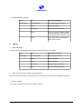
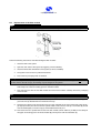
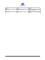
1
UrSpring Ultrafiltration Unit
For tips and tricks, support and sharing of your experiences visit
www.support.seccua.com
Page 2
Doc. Rev .100410
UrSpring Ultrafiltration Unit
Table of contents
1. User Information.......................................................................................................... 6
1.1 General............................................................................................................................................ 6
1.2 Guarantee Conditions.................................................................................................................... 6
1.3 Contact for service and technical support................................................................................... 7
2. Important Safety Instructions.....................................................................................8
3. Operating Conditions and System Layout................................................................ 9
3.1 Operating data of the system........................................................................................................ 9
3.2 System layout.................................................................................................................................. 9
1) Pressure shocks............................................................................................................................ 9
2) Filtration performance................................................................................................................... 9
3.3 Electrical connection.................................................................................................................... 10
4. System Description................................................................................................... 11
4.1 Dimensions and weight................................................................................................................ 11
1) Dimensions.................................................................................................................................. 11
2) Weight.......................................................................................................................................... 11
4.2 Components of the UF system.................................................................................................... 12
5. Installation.................................................................................................................. 13
5.1 General instructions..................................................................................................................... 13
5.2 Packing and package contents................................................................................................... 13
5.3 Electrical checklist....................................................................................................................... 13
5.4 Checklist casing and pre-filtration.............................................................................................. 13
5.5 Required tools and material......................................................................................................... 14
5.6 Preparations for installation........................................................................................................ 14
5.7 Unpacking and wall-mounting of the system ............................................................................14
5.8 Connection of the system to the water and sewage network.................................................. 15
1) Connections and general procedures.......................................................................................... 16
1 Connections............................................................................................................................ 16
2 Mounting with screwed connections....................................................................................... 16
3 Mounting with speedfit couplings........................................................................................... 16
2) Feed line...................................................................................................................................... 17
3) Filtrate line................................................................................................................................... 17
4) Drain line...................................................................................................................................... 17
5.9 Flushing and Commissioning...................................................................................................... 18
1) General........................................................................................................................................ 18
2) Flushing of the system................................................................................................................. 18
3) Commissioning............................................................................................................................ 18
Doc. Rev. 19122011
Page 3
UrSpring Ultrafiltration Unit
6. Operating States........................................................................................................ 19
6.1 Filtration ....................................................................................................................................... 19
6.2 Cleaning......................................................................................................................................... 19
6.3 Emergency operation mode........................................................................................................ 20
6.4 Sterilization of the system (e.g. after standstill)......................................................................... 20
7. Control and Programming........................................................................................ 21
7.1 Control panel of the control unit................................................................................................. 21
1) Overview keyboard...................................................................................................................... 21
2) LED lights and color code........................................................................................................... 22
3) Display......................................................................................................................................... 22
7.2 Menu structure and operation..................................................................................................... 22
1) Operation..................................................................................................................................... 22
2) Menu structure of the control unit............................................................................................... 22
3) Alarm........................................................................................................................................... 24
7.3 Programming................................................................................................................................ 24
1) Sleep mode................................................................................................................................. 24
2) Filtrate volume flow display......................................................................................................... 24
3) Input of the module's serial key................................................................................................... 24
4) Manual Flush............................................................................................................................... 25
5) Set flush mode and minimum filtration duration.......................................................................... 25
1 Setting the contamination-dependent cleaning:......................................................................26
2 Setting a daily flushing............................................................................................................ 27
3 Setting flush time..................................................................................................................... 27
4 Delaying of flushing during water usage.................................................................................. 28
6) Operating data ............................................................................................................................ 28
1 Display of the filter status........................................................................................................ 28
2 Pressure difference display..................................................................................................... 29
7) Settings....................................................................................................................................... 29
1 Setting language...................................................................................................................... 29
2 Units, time format, time of day, water temperature................................................................. 29
3 Factory settings....................................................................................................................... 29
4 Calibration............................................................................................................................... 30
8) Error display and error codes...................................................................................................... 30
8. Maintenance and Cleaning....................................................................................... 31
8.1 Storage of the filter module......................................................................................................... 31
1) General........................................................................................................................................ 31
2) Storage as a spare part............................................................................................................... 31
3) Storage after operation................................................................................................................ 31
8.2 Replacement of the filter module................................................................................................ 32
9. Troubleshooting......................................................................................................... 34
10. Limited Warranty......................................................................................................36
Page 4
Doc. Rev .100410
UrSpring Ultrafiltration Unit
11. Appendix...................................................................................................................38
11.1 Performance data....................................................................................................................... 38
11.2 Ultrafiltration module................................................................................................................. 38
Doc. Rev. 19122011
Page 5
UrSpring Ultrafiltration Unit
1.
User Information
1.1
General
The ultrafiltration (UF) installation simultaneously removes turbidity and pathogens from water supplied from surface,
spring or well water sources: Cost-efficiently, without the use of chemicals or radiation.
The fully automated conditioner uses extra-rugged, certified ultrafiltration membranes with pore sizes of less than
20 nanometers. 1,000 times smaller than those of a conventional micro-filter, the pores in the membrane nearly
completely remove viruses, bacteria and legionella from all types of raw water.
1.2
Guarantee Conditions
Please read the guarantee conditions carefully. You can find these in the chapter “ Limited Warranty“ at the end of
this user manual as well as in the general terms and conditions of the manufacturer . This system left our facilities
complete and in functioning condition. Please check the unit immediately upon receipt for completeness and possible shipping damage.
If the system or parts of the system have been damaged during transport, notify the transport company immedi ately. Transport damage to the system is not covered by the guarantee.
The guarantee cannot be claimed in the event of damages of the system caused by:
➢
Transport;
➢
Non-expert use or incorrect installation;
➢
Non-expert and/or insufficient maintenance;
➢
Operation of the system outside of the operating conditions described in this user manual; or
➢
Modifications to the system.
Important:
Please be sure that this user manual is always kept in the vicinity of the system and that it is handed over in the
event of a change in ownership.
Page 6
Doc. Rev .100410
UrSpring Ultrafiltration Unit
1.3
Contact for service and technical support
Should you require help with your system, please contact your service partner or dealer directly.
Customer support:
Every effort has been made to assure the completeness and readability of these operating instructions. If you have
any problems or questions, we would appreciate your letting us know so that we can improve this user manual.
Seccua GmbH
Krummbachstr. 8
86989 Steingaden
Germany
Tel. +49 (0) 8862 91172-0
Fax. +49 (0) 8862 91172-19
Seccua Americas LLC
15508 W. Bell Rd, Ste. 101-440
Surprise, AZ 85374
United States of America
Tel. +1 623 986-5766
Fax. +1 866 352 8178
Internet: www.seccua.com; Mail: [email protected]
Doc. Rev. 19122011
Page 7
UrSpring Ultrafiltration Unit
2.
Important Safety Instructions
Warning:
In addition to the instructions contained in this manual, be sure to heed all other safety and accident-prevention in structions!
Follow these additional directives for the safe operation of the system:
➢
Read this user manual carefully before the first commissioning.
➢
All installations and/or changes must be carried out by qualified experts.
➢
Install the system exactly as described in the user manual.
➢
Do not connect the system to the power mains if the connecting plug or cable is damaged.
➢
Only authorized service technicians should perform maintenance on this system. For any modifications or
repairs, contact your service partner.
➢
Do not expose any electrical cables to water.
➢
Do not kink the connecting cable. Ensure that it is safely and sufficiently attached.
➢
When performing any repairs, disconnect the system, remove it from the network and let it cool down.
➢
Electrical protective measures in accordance with VDE 0100 must be checked by authorized experts.
➢
Do not use any extension cords in the installation of the system.
➢
The maximum pressure difference (measuring points are upstream and downstream of the filter) may not
exceed 2.5 bar/36,26 psi.
➢
Avoid pressure shocks. These can be caused e.g. by shutting of external valves or switching of pumps in
the feed or filtrate line of the system.
Warning:
Caution: electrical voltage!
The power supply to the system must be interrupted before carrying out work on the control.
Page 8
Doc. Rev .100410
UrSpring Ultrafiltration Unit
3.
3.1
Operating Conditions and System Layout
Operating data of the system
Max. operating pressure
5.0 bar (=500 kPa, 73 psi)
Operating temperature
4°C to 40 °C (39 °F to 104 °F)
Water temperature
4°C to 40 °C (39 °F to 104 °F) (hot water variant
60°C/ 140°F)
Storage temperature
0 °C to +40 °C (32°F to 104 °F)
pH-range
pH value of 1 to 13 (during cleaning)
pH value of 2 to 11 (during operation)
Chlorine tolerance
In regard to free chlorine:
Total loading 200,000 (mg/l)xh,
200 mg/l max. concentration
Pressure difference feed – filtrate
0 – max. 2.5 bar (=250 kPa, 36 psi)
Separating limit (g/mol or Dalton)
100,000 – 150,000
Cleaning method
Manual and automatic flushing, time-interval controlled or dependent upon the degree of contamination (through monitoring of the pressure difference
and volume flow)
Note:
See further details about system performance in the appendix, starting on page Fehler: Referenz nicht gefunden.
3.2
System layout
1)
Pressure shocks
Rapidly closing valves, piston pumps and vertical pipe layouts can cause damaging pressure shocks. These, in turn,
can lead to filter damages in the membrane, damage to the pipeline network, the membrane itself as well as the
seals and additionally can cause deviations to system dimensions.
Pressure shocks normally occur through rapid starting, stopping or changes in the direction of flow. Any of these
causes can lead to catastrophic faults in the system. Rapidly closing valves, whether activated manually or automat ically, are without question the most frequent cause of pressure shocks in the application. A valve closing in 1.5
seconds or less (depending upon the size of the valve and the system conditions), can cause an abrupt break in the
flow. A pressure shock (audible wave) caused by a rapidly closing valve can easily amount to several times the normal system pressure.
2)
Filtration performance
The filtration performance of the system among other depends on the following parameters:
a) The utilized filter surface area of the system,
b) The flux rate, i.e. the flux rate (throughput per filter surface area)
Doc. Rev. 19122011
Page 9
UrSpring Ultrafiltration Unit
System type
Membrane surface area
UrSpring i6
8 m²
UrSpring i3
3.3
4 m²
Long-time flux rate
80 – 160 l/(m2h)
47 – 95 gfd
Flow rate at peak load
640–1.280 l/h
2.4 m3/h
(145-291 gal/h)
(545gal/h)
320–640 l/h
1.2 m3/h
(72-145 gal/h)
(272 gal/h)
max. 300l m²/h
Electrical connection
The system is supplied with a power supply plug and adapter for different mains plugs. The power supply plug
provides the system with the required supply voltage. An M12-plug (4-poles) is located at the other end of the cable in
order to connect to the covering hood.
Country
Voltage
Power (max.)
Frequency
Plug type
Germany
230 V
225 W
50 Hz
C
USA, Canada
120 V
225 W
60 Hz
B
China
230 V
225 W
50 Hz
D
Warning:
Electrical shock!
➢
Follow the instructions in this manual!
Failure to do so can cause serious injury or death!
➢
All electrical connections must be compliant with local ordinance and/or DIN/VDE directives!
➢
Do not modify the connecting plug or the connecting cable!
➢
Do not use extension cords!
➢
Before opening the cover, always disconnect the system from the power supply (pull the power supply plug)!
Page 10
Doc. Rev .100410
UrSpring Ultrafiltration Unit
4.
4.1
1)
System Description
Dimensions and weight
Dimensions
Diagram 1: Dimensions in mm
A distance of approx. 20 cm (8 inch) should be kept between the end-cap and the ground to enable an easy ex change of modules at a later point in time. There are four M8 threads on the rear of the valve block for wall mounting
of the system. For this, the bracket delivered with the four M8 cylinder head screws is attached to the valve block.
Now the complete system can be mounted on the wall with the bracket. For this purpose, there are four holes (with
a diameter of 9 mm) available, with a distance of 180 mm horizontally and 35 mm vertically. Viewed from the front,
the inlet (feed) is located to the left and the drain and filtrate outlet are to the right. All connections are 3/4"-threads
and equipped optionally with adapters (3/4" to pipe with 22mm outer diameter).
2)
Weight
System type
Weight (wet with module)
Construction length
Height inlet
UrSpring i6
approx. 15 kg (33 lbs)
1268 mm
1055 mm
UrSpring i3
approx. 15 kg (33 lbs)
1268 mm
1055 mm
Doc. Rev. 19122011
Page 11
UrSpring Ultrafiltration Unit
4.2
Components of the UF system
The system comprises a valve block with a covering hood and sensors as well as an ultrafiltration module and an
end cap at the bottom end. The attachment of the module to the block and the end-cap to the module is performed
by means of clamps, which are inserted in the surrounding grooves of the module housing and fastened with M8
cylinder head screws. Simple O-ring seals provide the required tightness of the system. The cover and control unit
of system are firmly connected to the valve block with four countersunk head screws.
Diagram 2: Components of the UF system
Page 12
Doc. Rev .100410
UrSpring Ultrafiltration Unit
5.
Installation
5.1
General instructions
Ensure that your shipment is complete and undamaged.
Note:
If your delivery is damaged or incomplete, please contact our service desk immediately.
5.2
Packing and package contents
The system is delivered preassembled. Please check the system after unpacking for damage and verify the secure
attachment of the screws.
5.3
Electrical checklist
Please make sure that the available electrical supply (power supply cable and socket) corresponds to the requirements of the system.
Note:
All electrical connections must be compliant with local ordinance and/or DIN/VDE directives!
Warning:
Electrical shock!
➢
Follow the instructions in this manual! Failure to do so can cause serious injury or death!
➢
Do not change the connecting plug or the connecting cable!
➢
Make sure the power supply cable is never in water!
➢
Do not use extension cords!
➢
Always disconnect the system from the power supply (pull the plug) before carrying out installation and main tenance work!
5.4
Checklist casing and pre-filtration
The system is delivered with two connection variants:
1.
The system is fitted with a metric 3/4" internal thread for connection of the feed, the filtrate as well as the
rinse water.
2.
Additionally, the system is supplied with 3/4" speedfit couplings, which are screwed into the valve block
and are sealed by means of an O-ring seal and are equipped with a speedfit coupling on the other side,
which is compatible with smooth pipe (copper or plastic) with an outer diameter of 22 mm.
Note:
Only utilize silicone grease (tape grease) or Teflon string for sealing screwed connections and never use fatty seal ant or hemp. The latter offers a culture medium for germ growth. Furthermore, it can be solved in the water and
cover the membrane with a layer of grease!
The connecting block of the system does not have to be removed during a later module replacement. Therefore, it
can be connected in a rigid manner.
The pressure in the system at rest may not exceed 5.0 bar. If necessary, install a pressure reducing valve.
Doc. Rev. 19122011
Page 13
UrSpring Ultrafiltration Unit
Note:
The system has been designed for a maximum water temperature of 40 °C. Additionally, the temperature of the wa ter in the feed may not drop below 4 °C (39°F).
To ensure smooth filtration operation and in order to prevent membrane damage due to rough particles, a pre-filter
(max. 300 μm) must be installed upstream of the system!
5.5
Required tools and material
Note:
We recommend that the system be installed and commissioned by a qualified installer.
The following tools and materials (not included!) are required for wall and in-line mounting:
➢
Drill, screws, wall plugs, four mounting screws
➢
Screwdriver
➢
Pipe wrench
➢
Measuring tape
➢
Bucket
➢
Silicone grease (depending on the installation type), Teflon tape or equivalent food grade sealing agent for use
with drinking water.
5.6
Preparations for installation
Mounting instructions:
Please check following points before mounting the device:
➢
Are all the necessary water connections available (feed raw water, rinse water, filtrate)?
➢
Is there a drain available at the location of installation (rinse water)?
➢
Is the necessary electrical connection available (power socket for power supply)?
➢
Please check whether the wall intended for mounting is suitable to carry the weight of the system (see chapter
4.1 “Dimensions and weight“) and ensure a sufficient safe attachment of the system with the wall!
➢
Is there sufficient space on the front side of the system to allow easy operation of the control unit and carrying
out of servicing and maintenance?
➢
Take sufficient space below the system into consideration in order to be able to easily perform later filter re placement (approx. 20 cm off the ground is sufficient)!
Warning:
Please observe all the relevant regulations at the time of installation!
The pressure in the system may not exceed 5.0 bar (72,5psi)! If necessary, please install a pressure reducing valve
to reduce the water pressure upstream of the system. In any case, the pressure difference between the feed and
filtrate may not exceed 2.5 bar (36,26 psi).
5.7
Unpacking and wall-mounting of the system
1.
Unpack the system.
2.
Secure the mounting plate with the supplied screws (M8) to the system.
3.
Check whether any connecting screws have been loosened from the system during transport. For this, use
the supplied Allen wrench.
Page 14
Doc. Rev .100410
UrSpring Ultrafiltration Unit
4.
When mounting the system to the wall, keep a distance of at least 20 cm between the bottom end of the fil ter and the floor in order to facilitate easy installation and removal of the filter module at a later date.
5.
Remove the power supply from the packaging, connect the M12 plug with the connector on the system
and hand-tighten it.
Diagram 3: Rear
view of the unit
with attached
bracket
5.8
Connection of the system to the water and sewage network
The systems are easily mounted and integrated into existing piping systems. All inlets and outlets are located on the
valve block of the system and are fitted with a uniform 3/4" internal thread. Furthermore, they are optionally
equipped with three adapters (3/4" internal thread to pipe with 22 mm outer diameter).
Note:
Use a commercial Teflon tape graded for use in a drinking water installation or permissible Teflon string for sealing
the connection threading. Do not use too much sealing material and be careful when screwing in the fittings. Other wise hair cracks could occur in the plastic and the thread could be damaged.
If you use the adapters, you do not require any additional sealing components as these are self-sealing. Never use
hemp for sealing!
We generally recommend installation of a shut-off option or a stop valve in the feed of the system, in the rinse water and in the filtrate line. This simplifies later maintenance and cleaning work.
The unit should be installed with detachable connections to be able to remove or exchange the unit later.
Doc. Rev. 19122011
Page 15
UrSpring Ultrafiltration Unit
1)
Connections and general procedures
1
Connections
Diagram 4: View of the left-hand
side with the feed connection
Diagram 5: View of the right-hand side
with filtrate and rinse water connection
The connections in the connection block are carried out as 3/4" internal threads (metric). The connection block is
made of plastic. The system is delivered with speedfit coupling adapters (3/4" external thread to pipe with 22 mm
outer diameter).
Note:
Before connecting the system with the pipeline network, any turning and other sharp-edged residue must be re moved from the pipework in the feed of the system in order to prevent damaging of the membranes.
2
3
Mounting with screwed connections
1.
The connection block of the system is made of plastic. Ensure that the internal thread of the connection
block is not damaged during installation of the component with the screwed connection.
2.
Only use pipes or fittings with a 3/4" metric external thread for screwing into the block.
3.
Only use Teflon string, Teflon tape or liquid Teflon for sealing the pipe that is to be connected. Do not use
hemp (which swells up in contact with water and can lead to damage of the block) or organic grease.
4.
Pay attention to the maximum thread reach (15 mm)
Mounting with speedfit couplings
1.
First screw the quick couplings into the connection block. The couplings seal against the block by means
of an O-ring. Therefore, the entire thread does not have to be sealed additionally.
2.
Put lubricant on the smooth pipe with an exterior diameter of 22 mm (copper or plastic)and push it into the
coupling until the noticeable resistance of the O-rings has been overcome.
Page 16
Doc. Rev .100410
UrSpring Ultrafiltration Unit
3.
Diagram 6: Insertion of the pipe in the quick
coupling
Diagram 7: The coupling engages before the Orings seal.
Diagram 8: Ensure that the inserted pipe has
been fully pushed into the quick coupling.
Diagram 9: Pull the pipe, in order to ensure that
a force-closed connection has been achieved.
The pipe is disconnected by simply pressing the release ring.
Diagram 10: Pressing in the sleeve enables removal of the pipe
Important:
Fully release the pressure from the system before opening the quick couplings.
2)
Feed line
Warning:
The trans-membrane pressure (pressure difference between feed and filtrate side) may not exceed 2.5 bar!
The pressure in the system at rest may never be greater than 5 bar!
3)
Filtrate line
Note:
It must be ensured that the filtrate can be drained off downstream of the system. An operating pressure (pressure
between the feed and filtrate side) of between 0.5 – 2.5 bar must be provided for filtration. A sampling petcock (“in terconnection point”) must be mounted immediately downstream of the installation!
Install a back flow preventer downstream of the system.
4)
Drain line
The drain line (rinse water) is required in order to discharge the water accumulating during flushing. Please note that
the nominal size of the drain line should correspond to the feed line pressure and type of system.
When routing the drain line, it must be ensured that no back flow of any type can form. Therefore, route the drain
line without any unnecessary bends and use adequately dimensioned pipe.
Doc. Rev. 19122011
Page 17
UrSpring Ultrafiltration Unit
Note:
An open separation must be provided between the system drain and the drain line in order to prevent re-contamin ation of the system due to drain water (free drain, in accordance with DIN 1988, Part 4, Design Classification A, as
per European Standard EN1717).
5.9
1)
Flushing and Commissioning
General
Before commissioning of the system, please first ensure that all impurities are removed from the connection lines in
order to avoid damage to the membrane and to guarantee a maximum filtrate quality.
Note:
It must be ensured that the unit is installed in a germ-free pipeline network and that no impurities are found in the
water downstream of the system. If necessary, the pipeline network between the system and the consumers must
be disinfected!
The systems are treated with a natural food preservative solution (sodium bisulfite) at the factory. This must be
rinsed out before commissioning of the system.
Pay attention that no metal or plastic turning or oil residue remains in the connection line, as this can damage the
membrane filter.
Any deposits must be removed before connection to the system!
2)
Flushing of the system
Proceed as follows for the flushing of the system:
1.
Install the system exactly as described above.
2.
Connect the power supply of the system (connect mains plug and plug in).
3.
When the system is turned on for the first time, the control unit will prompt the user to enter the serial number of the filter module. Follow the procedure as described in chapter 7.3 "Programming" (page 24).
4.
Begin the filtration and direct the filtrate downstream of the system into the drain.
Note:
Please ensure that the filtrate is discharged during the commissioning and flushing procedure and that it does not
reach any pure water containers or the supply network.
3)
5.
Rinse the system in this manner with at least 500 liters (130 gal) of water (approx. 15 minutes with a feed
pressure of approx. 1.5 bar (22 psi) and a free drainage at the collection point downstream of the system).
Make sure that the rinsed out water does not reach the line network downstream of the system.
6.
Slowly close the collection petcock downstream of the system.
7.
The flushing procedure of the system is now completed.
Commissioning
To finalize the commissioning the control has to be used to enter the module code, calibrate the sensors and adapt
the cleaning options if necessary. To see how to do this read in chapter 7 “Control and Programming“ the parts “Input of the module's serial key“ (page 24) and “Calibration“ (page 30) and “Set flush mode and minimum filtration
duration“ (page 25).
Page 18
Doc. Rev .100410
UrSpring Ultrafiltration Unit
6.
Operating States
6.1
Filtration
The actual ultrafiltration takes place in the operating mode “Filtration“. Water is forced from the feed side through
the membrane filter onto the filtrate side.
Note:
The instructions on the programming of the system can be found in chapter 7. “Control and Programming“ from
page 21.
Diagram 11: Depiction of a typical filtration cycle
A filtration cycle always lasts until an automatically triggered cleaning of the system occurs. A cleaning cycle is
triggered by the following:
1.
A threshold value of filter fouling is reached (e.g. decrease of the filter permeability, which is obtained from
the pressure difference and the volume flow), the example shown above for instance shows a decrease to
60% of the initial output.
2.
Additionally, it is performed at a certain time of day (this is for instance necessary in houses, which are not
inhabited continuously, in order to prevent water standing in the filter).
3.
However not before a minimum filtration length,which can be set has expired (this is important or else
strongly contaminated filters would be be flushed continuously).
4.
Not if water is being used, e.g. when a person is taking a shower (this function can be suppressed, when
the systems are for instance utilized in the inlet of an overhead tank). Flushing is then delayed until the wa ter usage is turned off.
If you have a UrSpring without the Dura-Kit option you can only do a cleaning cycle at one time of day.
6.2
Cleaning
During the cleaning of the system the membrane is flooded; no water flow takes place through the membrane.
Flushing should last about 10 seconds and the highest possible flow speed should be achieved. Usually it is sufficient when the feed pressure, which is present during filtration, is also used as the driving force during flushing.
Doc. Rev. 19122011
Page 19
UrSpring Ultrafiltration Unit
Note:
Generally speaking, the more turbid the raw water, the more frequently the membranes must be rinsed. Important:
With the correct settings, the system will adapt to fluctuating water qualities!
6.3
Emergency operation mode
If a fault occurs in the system, caused by excessive trans-membrane pressure, the system switches into the emergency operation mode and the flush valve opens automatically. This mode will protect the membrane against dam age as far as possible. However, membrane damage can occur even with a very brief exceeding of the permissible
maximum pressure difference between the feed and filtrate.
This emergency operation is maintained for 20 seconds, then the system will switch back into filtration operation.
6.4
Sterilization of the system (e.g. after standstill)
Depending upon the ambient temperature and the contamination of the raw water with dissolved organic compon ents (DOC), germ-growth takes place in standing water. The number of germs increases exponentially and can lead
to increased germ-counts on the pure water side downstream of the system. This contamination on the pure water
side of the system are not germs from the raw water (hence potential pathogens), but germs from the line network,
which were already present before the installation of the system.
Note:
Hence, attention must be paid to this during standstill-periods of the system: flushing the system must be carried
out at least every 24 hours. This measure serves the purpose of minimizing germ-growth in the system.
Note:
After a prolonged standstill of the ultrafiltration system, it must be washed out with a rinse with pure water before
renewed usage. A further, supplementary option is the disinfection of the system before the renewed commission ing.
Page 20
Doc. Rev .100410
UrSpring Ultrafiltration Unit
7.
Control and Programming
The intelligent control electronic ensures that the filtration cycles of the system are automatically adapted to the
fluctuating quality of the raw water. In this manner, it minimizes rinse water consumption and increases the comfort
level by preventing an interruption in supply during water removal.
7.1
Control panel of the control unit
Diagram 12: Control panel of the control unit
1)
Overview keyboard
Key
Name
Description
Enter
The Enter key activates the current or performed input or the currently shown
menu item. By pressing this key, the control advances to the associated submenu.
Arrow key up
Arrow key
down
Back
(Escape)
Doc. Rev. 19122011
Selection key in order to navigate up a level between individual menu items.
When pressing this key during the entry of numbers, the displayed value is increased.
Selection key in order to navigate down a level between individual menu items.
When pressing this key during the entry of numbers, the displayed value is de creased.
Cancel key: By pressing this key, the current menu is exited and next higher
menu is displayed. Any earlier input not activated by pressing enter is deleted.
Page 21
UrSpring Ultrafiltration Unit
2)
LED lights and color code
Color codes:
green = everything is OK
yellow = filter performance is reduced
red = alarm caused by an error (see error code) or the
The left LED lights up green during the filtration and in- filter is heavily contaminated!
dicates that the system is filtering correctly. If the left LED
If only the red LED blinks an error has occurred; if the
blinks, a flushing is performed.
yellow and red LEDs blink at the same time, an
The middle LED lights up yellow when the filter module is error/alarm must be read out.
contaminated and a filter change should be taken into
consideration soon.
The right LED blinks red in the case of alarms and when
indicating a required filter change.
3)
Display
The control panel has a single line display comprised of up to 16 characters. All communication with the control unit
in regard to the selection of the menu and the performance of parameter changes is carried out via this display.
When the system is connected to the power mains, the control unit automatically switches into the permanent
volume flow display (depending on the pre-set units either in liters per minute or gallons per minute).
Note:
The control unit of the system is pre-set to your relevant requirements at the factory in regard to the units and lan guage. The display has the option of an automatic time-out, after which the lighting is switched off. All systems are
pre-set to continuous lighting.
7.2
Menu structure and operation
The control unit of the system is laid out in a simple and clear manner. It is restricted to the essential functions of an
ultrafiltration system, the filtration, the cleaning of the filter module and certain monitoring functions.
1)
Operation
The display has a line in which the relevant menu item or the values to be entered are displayed. After switching on
(connection with the mains plug), the control unit shows the filtrate volume flow display. The control unit continuously monitors and measures the volume flow, the feed and the filtrate pressure. Conclusions about filter fouling and
system output can be drawn from these values.
2)
Menu structure of the control unit
See next page.
If you have a UrSpring without the Dura-Kit option some of the settings are meaningless as there are no sensors that
are necessary to calculate a differential pressure and fouling.
Page 22
Doc. Rev .100410
UrSpring Ultrafiltration Unit
Diagram 13: Menu structure
Doc. Rev. 19122011
Page 23
UrSpring Ultrafiltration Unit
3)
Alarm
All alarms are displayed by the lighting up of the red LED and can be read out and acknowledged via the menu "Er ror/Alarm". The acknowledgement of an alarm is performed by pressing the Enter key.
Note:
If an alarm occurs in the system, always determine the type of the alarm first, then eliminate the cause of error if
possible. If the same alarm occurs repeatedly, please contact your service partner.
An alarm with an opened flush valve can stop filtration until acknowledgement has been performed or the cause of
the error has been eliminated!
An index of the alarm messages can be found in chapter 9. "Troubleshooting" (page 34).
7.3
Programming
The system is delivered with a control unit that is pre-configured for your requirements. The language and the units
of the system are already configured. Therefore, the following descriptions are in regard to the possible modifica tions of the settings on site.
1)
Sleep mode
The control unit provides the option of changing into a sleep mode. In this mode all settings are retained, the system
continues to filter and only the display lighting is automatically turned off after a certain amount of time.
Note:
We recommend returning to the display of filtrate volume flow after each programming. In this manner, it is always
visible how much clean drinking water the system is currently producing.
2)
Filtrate volume flow display
Depending on the settings, in this state the current filtrate volume flow of the system is displayed. In general there
are two possibilities. Either the filtrate volume flow can be displayed in liters per minute or in gallons per minute.
After switching on the system (connection with the mains), the control unit automatically displays this.
3)
Input of the module's serial key
At the first activation as well as after a filter replacement of the system, the module code of the filter must be reentered. This contains factory data on the module type and each individual module. This code is noted on the serial
number label, which is located on the module (e.g. "Code: 000123"). To perform this, after connection of the system,
switch into the menu "Settings" and select the menu item "Serial Key". Follow the procedure described below:
Page 24
Doc. Rev .100410
UrSpring Ultrafiltration Unit
4)
Start
Key
Result (Display examples)
Flow 0.0 gpm
Arrow key down
Until "Settings" is shown.
Enter
Display "Language"
Arrow keys
Display "Serial Key"
Enter
Display "Number:_"
Arrow keys
Enter 7-digit number shown on module
Enter
Switches to the next number,
key "Back" switches to the previous
one.
Press enter after the last
number
Jumps back to the menu "Serial Key"
Back
Display "Settings", You are back in the
main menu.
Manual Flush
The filter module of the system can be rinsed and cleaned manually at any time; perform the following to do this:
Start
Key
Result (Display examples)
Flow 0.0 gpm
Arrow key down
Until "Manual Flush" is shown.
Enter
Display "Start flushing?"
Enter
Flushing is started (feed pressure must
be present)
Display "Stop flushing?"
Enter
Flushing is stopped.
Display "Start flushing?"
Back
Main menu item
Display "Manual Flush"
5)
Set flush mode and minimum filtration duration
With this menu item the filtration and rinse cycles of the system can be programmed.
Doc. Rev. 19122011
Page 25
UrSpring Ultrafiltration Unit
1
Setting the contamination-dependent cleaning:
Start
Key
Result (Display examples)
Flow 0.0 gpm
Arrow key down
Until "Flush Mode" is shown.
Enter
Display "Clean at fouling?"
Enter
Display "when flow < 60%"
Arrow keys
Setting the threshold value which, when
reached, triggers a cleaning cycle. The
value is determined from volume flow,
temperature and the pressure difference
and in this manner indicates the actual
contamination of the filter.
Enter
Ends the entry and opens the menu for
entering the minimum filtration duration.
Display "Set hours: 00:30"
Arrow keys
Setting the hours of the minimum filtration duration between two cleaning
cycles via the arrow keys.
Enter
Ends the entry.
Display "Set min: 00:30"
Arrow keys
Setting the minutes of the minimum filtration duration between two cleaning
cycles via the arrow keys.
Enter
Ends the entry and jumps back to the
menu "Flush mode"
Display "Clean at fouling?"
Page 26
Doc. Rev .100410
UrSpring Ultrafiltration Unit
2
Setting a daily flushing
Start
Key
Result (Display examples)
Flow 0.0 gpm
Arrow key down
Until "Flush mode" is shown.
Enter
Display "Clean at fouling?"
Arrow keys
Until "Flush daily at?" is shown.
Enter
Display "Set hour: 00:30"
Arrow keys
Setting the time of day at which a cleaning is performed. First the hours are set
via the arrow keys.
Enter
Ends the entry.
Display "Set minutes: 00:30"
Arrow keys
Setting the minutes via the arrow keys.
Enter
Ends the entry and jumps back to the
menu "Flush Mode"
Display: "Flush daily at?"
Arrow key down
Until "Daily=OFF" is shown.
Enter
Display "Daily: OFF"
Arrow keys
Switch between "ON" and "OFF"
Enter
Ends the entry and jumps back to the
menu "Flush"
Display "Daily=ON"
3
Setting flush time
Start
Key
Result (Display examples)
Flow 0.0 gpm
Arrow Key down
Until „ Flushmode“ is shown
Enter
Display „clean at fouling“
Arrow Key down
Until „Flush length“ is shown
Enter
Display „20 Seconds“
Arrow Key up
Flush length increases
Arrow Key down
Flush length decreases
Enter
Setting is saved.
Display „Flush length“
Doc. Rev. 19122011
Page 27
UrSpring Ultrafiltration Unit
4
Delaying of flushing during water usage
With this function it can be avoided that flushing is performed during water usage and in this manner the water flow
is interrupted. It is recommended to activate this function only when the system is installed in the direct inlet of a
house or an apartment.
Important
This function must be deactivated when the system is for instance being used for filling a storage tank, as this
would suppress a flushing permanently in the case of continuous volume flow.
Flushing is delayed until water usage is stopped.
Start
Key
Result (Display examples)
Flow 0.0 gpm
Arrow key down
Until "Flush mode" is shown.
Enter
Display "Clean at fouling?"
Arrow keys
Until the display of "Flush when flow?"
Enter
Display "Set: NO"
Arrow keys
Changing the status
Enter
Setting is saved.
Display "Flush when flow?"
6)
Operating data
1
Display of the filter status
Start
Key
Result (Display examples)
Flow 0.0 gpm
Arrow key down
Until "Operating Data" is shown.
Enter
Display "Filter State"
Enter
Display of the filter state in % of the filter performance in regard to the new
condition of the filter. This value is first
recorded after the first cleaning.
Enter
Return to the menu "Operating data".
Display "Filter State"
Page 28
Doc. Rev .100410
UrSpring Ultrafiltration Unit
2
Pressure difference display
Start
Key
Result (Display examples)
Flow 0.0 gpm
Arrow key down
Until "Operating Data" is shown.
Enter
Display "Filter State"
Arrow keys
Until "Diff. Pressure" is shown.
Enter
Display of the pressure difference (feed
pressure minus filtrate pressure) directly
at the membrane filter. Unit is bar or psi.
Enter
Return to the menu "Operating data".
Display "Diff. Pressure"
7)
Settings
1
Setting language
The system can be operated both with a German as well as an English menu display.
2
Start
Key
Result (Display examples)
Flow 0.0 gpm
Arrow key down
Until "Settings" is shown.
Enter
Display "Language"
Enter
Display "German"
Arrow keys
Choose "English" or “German”
Enter
Saves the selected language
Units, time format, time of day, water temperature
Similar to the above described procedure the units, time format, time of day and water temperature can be set.
3
Factory settings
This function resets the system back to the factory settings.
Doc. Rev. 19122011
Page 29
UrSpring Ultrafiltration Unit
4
Start
Key
Result (Display examples)
Flow 0.0 gpm
Arrow key down
Until "Settings" is shown.
Enter
Display "Language"
Arrow key down
Until "Set Default?" is shown.
Enter
Display "Set Default: YES"
Arrow keys
Select YES or NO
Enter
Confirms the selection
Calibration
With this, the analogue sensors of the system (pressure sensors in the feed and filtrate) are calibrated. Return the
system to an absolutely pressure-less state before performing the calibration, for instance by manually blocking the
feed as well as the filtrate line and performing a manual rinse (as described in chapter 5.9 “Flushing and Commissioning“). During the flushing, the pressure in the system is equalized with the atmospheric pressure.
Start
Key
Result (Display examples)
Flow 0.0 gpm
Arrow key down
Until "Settings" is shown.
Enter
Display "Language"
Arrow key down
Until "Calibrate Now?" is shown.
Enter
Display "Disconnect Water"
Enter
Calibrates the zero-point of the sensors.
Display "Adjustment o.k.!"
Enter
8)
Jumps back to the menu "Settings"
Error display and error codes
The last occurring error is displayed in the error menu.
Start
Key
Result (Display examples)
Flow 0.0 gpm
Arrow key down
Until "Error / Alert" is shown.
Enter
Display "Last Error 104"
Enter
While the error is displayed, the message can be acknowledged by pressing
the enter key. If no error message is
present, the user is returned to the main
menu.
The error codes are explained in chapter 9 “Troubleshooting“.
Page 30
Doc. Rev .100410
UrSpring Ultrafiltration Unit
8.
Maintenance and Cleaning
The systems are designed for low-maintenance when the settings have been optimized for the individual requirements of the user and the information contained in the user manual is followed. The intelligent control software auto matically recognizes possible errors and informs the user by means of the alarm signal, the red LED, which lights up
on the display.
8.1
1)
Storage of the filter module
General
The filter module was conserved with the conservation medium E223 (sodium bisulfite) and shipped.
Note:
The filter module does not contain any anti-freeze agent. Therefore, the ultrafiltration module may not be exposed
to frost, as this can lead to damage of the membrane!
2)
Storage as a spare part
Originally packed SMP-modules can be stored for up to two years under the following conditions:
3)
1.
The original packaging must not be removed and must not be damaged, so the modules are prevented from
drying out
2.
The modules may not be exposed to direct sunlight and must be stored in a cool, dry place.
3.
The storage temperature must be between 2 and 20°C (35-68°F).
4.
The module is stored vertically with the connections upwards.
Storage after operation
A filter module, which has already been rinsed and taken into operation, can be safely stored for up to six months,
after a thorough flushing with pure water and adding a 1% sodium bisulfite solution to avoid biological growth and
contamination. For storage that is longer than six months, the module must be washed out again – cleaned in the
case of strong contamination – and rinsed and handled as described above. In any case, the ultrafiltration module
must be rinsed out with an adequate quantity of pure water (clean drinking water) before renewed usage.
Make sure the modules are sealed using the original Seccua protective end caps and are prevented from drying out
as well as stored in a cool and dry place. Store the modules vertically with the opening facing upwards.
Doc. Rev. 19122011
Page 31
UrSpring Ultrafiltration Unit
8.2
Replacement of the filter module
Note:
We recommend having the filter module in the system dismantled and replaced by an authorized service partner!
Diagram 14: Module replacement
Follow the following instructions when dismantling the filter modules:
1.
Close the inlet to the system.
2.
Open the drain valve of the system by triggering a manual flushing.
3.
Close the filtrate-line downstream of the system (if valve is available).
4.
The system must now be in a pressure-less state!
5.
Ensure that any escaping water is collected.
Warning:
Ensure that the system is completely free of pressure when removing the filter module. If the system is not pressure-less, there is the risk of injury and nothing may be changed in the system!
6.
Unscrew the end cap (C) from the module (B) by loosening the four cylinder head screws and take both
side clamps out of the surrounding groove in the filter module.
7.
Now open the box with the new filter module and remove the module. Carefully remove the packaging
on the module.
Note:
For this, see also the assembly instructions in this user manual on page 14!
8.
Place the new, unpacked module (flat side down) centered above the end cap, so that the O-ring in the
groove of end cap lies between the module and the cap.
9.
Place the two clamps in the surrounding groove on the underside of the new module and screw this finger-tight (max 5Nm) from above with four cylinder head screws onto the end cap. The module (B) should
now be seated tightly on the end cap (C) and be fastened securely to it.
10. Now loosen the four cylinder head screws one after another (with an Allen key for M8) on the clamps in
the upper surrounding groove of the old module (B), which joins it with the valve block (A).
Page 32
Doc. Rev .100410
UrSpring Ultrafiltration Unit
Warning:
The ultrafiltration module can weigh up to approx. 10 kg/22 lb! The weight of the module must be secured when
the screwed attachment between the module and the valve block is loosened!
11. Remove the old ultrafiltration module from the system and ensure that the O-ring (part no. 10549), which
is placed in the groove of the valve block (underside), is not lost. This remains on the valve block and is
reused for the new filter module, as long as it is not damaged.
12. Insert the new filter module (B) with the end cap (C) mounted earlier centrally in the valve block (A) from
below. Carefully push the module upwards to a dead stop. Ensure the correct position of the O-ring seal!
13. Place the two clamps in the surrounding groove on the upper side of the new module and screw this finger-tight (max 5Nm) from the bottom with the remaining four cylinder head screws onto the valve block
(A). The new module (B) with the end cap (C) should now be seated tightly against the cover (A) under
the valve block and securely connected to it.
14. Carry out a cleaning of the system.
15. You can now take the system back into operation.
Doc. Rev. 19122011
Page 33
UrSpring Ultrafiltration Unit
9.
Troubleshooting
Problem / alarm code
Possible cause
Solution
101
The emergency flush is running or has run. This
alarm is activated when the maximum permissible membrane pressure is exceeded, in order to
avoid damage to the membrane.
Seek for the cause of the possible exceeding
of the pressure difference. This may not ex ceed a pressure difference of 2.5 bar (36psi)
between the feed and filtrate side at maximum
water consumption.
102
Permeability is too low.
Contact your service technician.
103
Info, that the filter should be changed soon.
Prepare the replacement of the filter, if re quired, order a replacement filter.
104
Indicates that the last cleaning could not raise
the performance of the filter above the set
threshold value for cleaning.
Check the set minimum filtration length as well
as the threshold value at which a cleaning is
triggered. If required, shorten the minimum fil tration length (to 20 minutes) and set the
threshold value to 60%. It should be possible
for the system to then incrementally regain its
performance in the course of the next days .
105
Problem with power supply.
Check the power supply and socket.
106
Ambient temperature above 40°C (104°F)
Take measures to lower temperature in ambi ent of unit.
107
Ambient temperature below 0°C (32°F)
Make sure that water does not freeze. The
electronic control will work also below 0°C.
108
Excessive trans-membrane pressure (TMP >=
2.5 bar/ 36,26 psi), risk of filter damage!
Seek for the cause of the possible exceeding
of the pressure difference. This may not ex ceed a pressure difference of 2.5 bar/36,26 psi
between the feed and filtrate side at maximum
water consumption.
109
The sensors are not functioning correctly.
Contact your service technician.
115
Memory error.
Contact your service technician.
The valve does not switch,
the display remains dark
The power connection is faulty.
Verify that the power cable/mains plug is connected and inserted properly.
The control unit is defective or the software on Replacement of the control unit/cover or
your system has an error.
flashing of functioning software by your service partner.
The valves of the system were not connected Have an authorized installer or electrician concorrectly with the control unit /cover.
nect the valve with the control unit/cover.
No water comes from the filtrate outlet
Blocking device in the feed line to the system (if Open the blocking device.
installed) closed.
Malfunction of the valve of the system or an Verify the function of the valve. If necessary,
alarm occurrence, which has led to a perman- have this replaced by your service partner.
ent opening of the drain valve.
Check whether an alarm has occurred in the
system. If this is the case, acknowledge the
error.
Wait until the rinse cycle has been completed.
An insufficient amount of wa- System is in the rinse cycle.
ter comes out of the filtration
outlet
Membrane capillaries are strongly contaminated Start a rinse as described in the user manual.
with particles from the raw water (filtrate volume
flow was higher at the time of commissioning
Page 34
Doc. Rev .100410
UrSpring Ultrafiltration Unit
Problem / alarm code
Possible cause
Solution
and has reduced during operation).
Intervals between the rinse cycles is too long Adjust the settings for the flushing of the sys(filtrate volume flow was higher at the time of tem depending on the raw water quality and
commissioning and has reduced during opera- reduce the set cycles up to flushing.
tion).
Feed pressure to the system is too low.
Contact your service partner or installer and
ask them about possibilities for increasing the
pressure upstream of the system.
Water suddenly tastes bad
The conservation solution of the filter module The module is conserved with a harmless
was not rinsed out completely.
solution. Rinse the system at the time of commissioning or after the replacement for a new
module for a sufficiently long time to remove
the conservation solution.
Flushing runs for too long.
Incorrect setting in the program
Doc. Rev. 19122011
Change the settings in the control unit as described on page 25 ff.
Page 35
UrSpring Ultrafiltration Unit
10.
Limited Warranty
This system was manufactured to the highest quality standards. The warranty and guarantee conditions of our general terms and
conditions apply.
The guarantee voids if the system is not operated, stored, transported or mounted properly according to the conditions described
in this manual.
Warning
The removal performance of pathogens by ultrafiltration membranes is very high. The manufacturer has specified removal rate of
99.99% for viruses and 99.999% for bacteria. However, complete germ-removal cannot be guaranteed by any technical system –
even with an ultrafiltration membrane.
The warranty obligor for each Region or country of purchase is identified below and is referred to as ”Seccua“ herein. Seccua‘s
warranty obligations are limited to the terms set forth below.
Warranty Coverage. Seccua warrants Seccua-branded hardware against defects in materials and workmanship when installed and
operated within Seccua‘s specifications for a period of ONE (1) YEAR from the date of startup by the original end-user, or eighteen
(18) months from date of ex-factory shipment from Seccua, whichever comes first (”Warranty Period”). If a hardware defect arises
and a valid claim is received within the Warranty Period Seccua will, at its option, exchange the part with a new, or refurbished
part that is at least functionally equivalent to the original part. A replacement part assumes the remaining warranty of the original
part. When a part is exchanged, any replacement item becomes the original end-user’s property and the replaced item becomes
Seccua‘s property.
Exclusions and limitations. This Limited Warranty applies only to hardware parts manufactured by or for Seccua that may be identi fied by the “Seccua” trademark, trade name, or logo affixed to them. The Limited Warranty does not apply to any non- Seccua part
or any software, even if packaged or sold with Seccua hardware. Manufacturers, suppliers, or publishers, other than Seccua, may
provide their own warranties, but Seccua, in so far as it is permitted by law, provides its parts “as is”. Software distributed by Seccua with or without the Seccua brand name (including, but not limited to system software) is not covered under this Limited War ranty. Refer to the licensing agreement accompanying the software for details of your rights with respect to its use.
Seccua does not warrant that the operation of the part will be uninterrupted or error-free. Seccua is not responsible for damage
arising from failure of the parts.
This warranty does not apply: (a) to damage caused by non-Seccua products; (b) to damage caused by accident, abuse, misuse,
flood, fire, earthquake or other external causes; (c) to damage caused by operating the part outside the permitted uses described
by Seccua; (d) to damage caused by service (including upgrades and expansions) performed by anyone who is not a representative of Seccua or a Seccua Authorized Service Provider authorized to perform service; (e) to a part that has been modified to signi ficantly alter functionality or capability without the written permission of Seccua; (f) to consumable parts, such as filter modules,
unless damage has occurred due to a defect in materials or workmanship; or (g) if any serial number has been removed or de faced.
TO THE EXTENT PERMITTED BY LAW, THIS WARRANTY AND REMEDIES SET FORTH ABOVE ARE EXCLUSIVE AND IN LIEU OF
ALL OTHER WARRANTIES, REMEDIES AND CONDITIONS, WHETHER ORAL OR WRITTEN, STATUTORY, EXPRESS OR IMPLIED.
AS PERMITTED BY APPLICABLE LAW, SECCUA SPECIFICALLY DISCLAIMS ANY AND ALL STATUTORY OR IMPLIED WARRANTIES, INCLUDING, WITHOUT LIMITATION, WARRANTIES OF MERCHANTABILITY, FITNESS FOR A PARTICULAR PURPOSE
AND WARRANTIES AGAINST HIDDEN OR LATENT DEFECTS. IF SECCUA CANNOT LAWFULLY DISCLAIM STATUTORY OR IM PLIED WARRANTIES THEN TO THE EXTENT PERMITTED BY LAW, ALL SUCH WARRANTIES SHALL BE LIMITED IN DURATION
TO THE DURATION OF THIS EXPRESS WARRANTY AND TO REPAIR OR REPLACEMENT SERVICE AS DETERMINED BY SECCUA IN ITS SOLE DISCRETION. No Seccua reseller, agent, or employee is authorized to make any modification, extension, or addition to this warranty.
TO THE EXTENT PERMITTED BY LAW, SECCUA IS NOT RESPONSIBLE FOR DIRECT, SPECIAL, INCIDENTAL OR CONSEQUEN TIAL DAMAGES RESULTING FROM ANY BREACH OF WARRANTY OR CONDITION, OR UNDER ANY OTHER LEGAL THEORY,
INCLUDING BUT NOT LIMITED TO LOSS OF REVENUE; LOSS OF ACTUAL OR ANTICIPATED PROFITS (INCLUDING LOSS OF
PROFITS ON CONTRACTS); LOSS OF THE USE OF MONEY; LOSS OF ANTICIPATED SAVINGS; LOSS OF BUSINESS; LOSS OF
OPPORTUNITY; LOSS OF GOODWILL; LOSS OF REPUTATION; LOSS OF, DAMAGE TO OR CORRUPTION OF DATA; OR ANY IN DIRECT OR CONSEQUENTIAL LOSS OR DAMAGE HOWSOEVER CAUSED INCLUDING THE REPLACEMENT OF EQUIPMENT
AND PROPERTY. THE FOREGOING LIMITATION SHALL NOT APPLY TO DEATH OR PERSONAL INJURY CLAIMS. SECCUA SPE CIFICALLY DOES NOT REPRESENT THAT IT WILL BE ABLE TO REPAIR ANY PART UNDER THIS WARRANTY OR MAKE A PART
EXCHANGE WITHOUT RISK OF INTERRUPTION OF WATER SUPPLIES. SECCUA SPECIFICALLY DOES NOT REPRESENT FULL
REMOVAL OF PATHOGENS BY ITS SYSTEMS AT ALL TIMES.
Consumer Protection Laws. FOR CONSUMERS WHO HAVE THE BENEFIT OF CONSUMER PROTECTION LAWS OR REGULA TIONS IN THEIR COUNTRY OF PURCHASE OR, IF DIFFERENT, THEIR COUNTRY OF RESIDENCE, THE BENEFITS CONFERRED
BY THIS WARRANTY ARE IN ADDITION TO ALL RIGHTS AND REMEDIES CONVEYED BY SUCH CONSUMER PROTECTION
LAWS AND REGULATIONS. Some countries, states and provinces do not allow the exclusion or limitation of incidental or consequential damages or exclusions or limitations on the duration of implied warranties or conditions, so the above limitations or ex clusions may not apply to you. This warranty gives you specific legal rights, and you may also have other rights that vary by coun try, state or province. This Limited Warranty is governed by and construed under the laws of the country or state in which the part
purchase took place.
Page 36
Doc. Rev .100410
UrSpring Ultrafiltration Unit
Region
Seccua
Address
The Americas
Seccua Americas LLC
15508 West Bell Road, Suite 101-440,
Surprise, AZ (85374 (USA)
All other countries
Seccua GmbH
Krummbachstr.
Germany
Doc. Rev. 19122011
8,
86989
Steingaden,
Page 37
6
&*