1
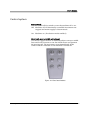
User’s Manual
English
In-Line
Destacker
User´s Manual
This manual is intended for the inline device specified on the previous page. The manual contains information
to assist the operator to start and operate the device properly, and to maintain it. Hardware and software
mentioned in this document are subjected to continuous development and improvement. Consequently, there
may be minor discrepancies between the information in the document and the performance and design of the
hardware and software. Specifications, dimensions and other statements mentioned in this document are
subject to change without prior notice.
Conventions
In this manual angle brackets <> are used to indicate certain button names. Example: <Enter> stands for the
ENTER button.
Manufacturer and its suppliers shall not be liable for any damages related to the software or hardware, or for any other damages whatsoever caused of the use of
or inability to use any manufacturer product. This is applicable even if manufacturer has been advised of the damage risk. Under any circumstances,
manufacturer’s entire liability shall be limited to replace such defective software or hardware which was originally purchased from
manufacturer.
Printed in Sweden.
MB760_061121u.doc/ 4/12/2007
2
User´s Manual
Contents
1.
SAFETY........................................................................................................................... 4
Warning sign ......................................................................................................................... 5
Warnings ................................................................................................................................ 5
2.
ABOUT THE DOCUMENTATION ................................................................................ 6
User's manual......................................................................................................................... 6
3.
INSTALLATION ............................................................................................................. 7
Setting up the machine for operation ................................................................................. 9
4.
PRODUCT DESCRIPTION........................................................................................... 10
Main parts ............................................................................................................................ 10
Control system .................................................................................................................... 12
5.
MAINTENANCE .......................................................................................................... 14
Maintenance schedule ........................................................................................................ 14
Maintenance instructions................................................................................................... 14
Figures
Figure 1-1 Electric shock .......................................................................................................5
Figure 1-2 Attention..............................................................................................................5
Figure 4-1 Main parts..........................................................................................................10
Figure 4-1 Hand unit buttons.............................................................................................12
MB760_061121u.doc/ 4/12/2007
3
User´s Manual
1. Safety
Before starting the machine it is essential that the operator, the
foreman, and any other personnel involved in the machine
operation understand the following:
•
Trained personnel must operate the machine only.
•
Anyone operating this machine must obey all warning
signs. See the section entitled Warning Sign in this chapter.
•
Do not use chemicals or other substances which may have
any influence on the operator or other personnel involved
in the machine operation.
•
Apart from weekly and monthly maintenance as described
in the Maintenance chapter of the User's Manual, the
machine is to be serviced by authorized personnel only.
•
All covers and shields must be intact, mounted and closed
while the machine is in operation.
•
Do not disable or disengage any built-in safety switches or
sensors.
•
No hands or fingers are allowed in the vicinity of the
moving parts of the machine.
MB760_061121u.doc/ 4/12/2007
4
User´s Manual
Warning sign
The warning sign on the machine must be observed as this
machine contains electrically live parts.
The warning sign on the machine is placed on the cover of the
electrical cabinet.
The sign must be kept clean and readable.
Figure 1-1 Electric shock
If the sign is missing, it must be replaced immediately.
This sign warns of electric shock. Units on which this sign is
placed contain dangerous voltage levels. Power must be
switched off before opening the unit. Only authorized service
personnel are allowed to operate the machine when the unit is
open.
Warnings
Throughout the manual this symbol is used to call your
attention to commands that start machine movements. The
symbol refers to the warning signs, which must be obeyed to
eliminate the risk of injury.
If there are instructions accompanying this symbol, they must
be followed.
Figure 1-2 Attention
MB760_061121u.doc/ 4/12/2007
5
User´s Manual
2. About the documentation
User's manual
The User's Manual contains information to assist the operator
to start and operate the machine properly.
The User's Manual is divided into the following
main parts:
Chapter l: Safety instructions.
Chapter 2: Information about the documentation.
Chapter 3: Installation instructions.
Chapter 4: Description of the machine and its basic operation.
Chapter 5: Maintenance instructions.
MB760_061121u.doc/ 4/12/2007
6
User´s Manual
3. Installation
Delivery
The machine is delivered fixed on a pallet.
Preparation
Before installation, prepare the location so that electric power
and pressurized air is available.
Ambient conditions
The ambient air must be clean.
Allowed humidity:
0 to 35'C
35 to 60'C
10 to 90 % noncondensing
10 to 60 % noncondensing
Allowed temperature:
Operating
5 to 40 'C (41 to 104 'F)
Storage
-40 to 60 'C (-40 to 104 'F)
Technical data
Weight
Length
Depending on actual size.
500 mm (19.7”)
Voltage
100-240 VAC
Frequency
Power consumption,
50/60 Hz
max. 300 W
MB760_061121u.doc/ 4/12/2007
7
User´s Manual
Lifting information
The machine can be lifted with a forklift truck. Put some
wooden boards between the forks and the bottom metal part.
Installation
Authorized service personnel must carry out the installation.
The complete production line must be carefully levelled along
the destacker belts. Use a spirit level across and along the
destacker belts when adjusting the feet of the machine.
The fundament must be rigid and sturdy. The machine must
not rock.
The machine must be placed in a manner that allows access to
all parts of the machine and so that service actions are not
obstructed. There must be a free space of one meter around the
machine, except for the other machines included in the
production line.
Joining the units
Frameworks of the units to be joined are bolted together with
plates and screws.
Mains supply
To be connected by authorized electrician.
Allowed primary voltage is 100 to 240 VAC 50/60 Hz.
MB760_061121u.doc/ 4/12/2007
8
User´s Manual
Setting up the machine for operation
Fix the destacker to the preceding and/or subsequent machine.
Connect power and smema cables.
Set the width of the destacker. Make sure the PCB can be moved
manually through the whole destacker length without getting
stuck. The total PCB gap should be around 1 mm.
See following pages for information on how to adjust the
destacker for different board thicknesses. Put a bundle of boards
in the destacker and set the destacking function to on. If PCBs
are not destacked properly, try to adjust conveyor width and/or
PCB thickness.
The destacker is equipment with a green status indicator. The
status indicator has three states. Light on, light off, or flashing.
Light on:
The machine is in production and no error has
occurred.
Flashing:
Low stack or empty.
Light off:
Power off, PCB not destacked properly, or
PCB jammed during infeed or outfeed.
MB760_061121u.doc/ 4/12/2007
9
User´s Manual
4. Product description
Main parts
D
A
E
B
F
C
G
Figure 4-1 Main parts
A.
B.
C.
D.
E.
F.
G.
MB760_061121u.doc/ 4/12/2007
Knob for board thickness adjustment
Hand control unit
Power On/Off switch
Status indicator
Moving rail
Fixed rail
Electrical cabinet
10
User´s Manual
Function
The Destacker (D) is designed to enable a stack of boards to be
placed in the destacker’s magazine and then be destacked one
by one from the bottom of the stack and lowered down to the
conveyor which transports the PCBs to the subsequent
machine. If the magazine becomes empty, or the destacking
function on the hand unit is set to off, the D turns into a
conveyor which transfers PCBs from one machine to another.
When there is a board on the D, a signal is given to the
upstream machine that says that the D is busy. When the
subsequent machine signals that it is ready to receive a board,
the board is fed out from the D. When the D is empty, the
preceding machine gets a signal that says that the D is ready to
receive a board.
MB760_061121u.doc/ 4/12/2007
11
User´s Manual
Control system
Power switch
Use the Power Off/On switch to turn the machine off or on.
Off: Machine off. All electrically controlled movements are
stopped and mains supply is disconnected.
On: Machine on. (Production mode enabled.)
Hand unit, manual width adjustment
Use the two upper buttons to manually adjust conveyor width.
Press and hold a button to run the width motor and position
the moving rail. The movement stops immediately if the
control switch is released or the machine is turned off.
Figure 4-1 Hand unit buttons
MB760_061121u.doc/ 4/12/2007
12
User´s Manual
Hand unit, automatic width adjustment (option)
Use the button marked ‘AUTO’ to turn automatic width
adjustment off or on. An LED positioned above the button is lit
when the function is ON.
OFF:
Automatic width adjustment off.
Width information sent from previous machine is
ignored. Manual width adjustments are enabled.
ON:
Automatic width adjustment on.
Width is adjusted automatically based on width
information received from previous machine, or
based on width entered in the optional auto width
control unit (K-017-0488). The two width adjustment
buttons for manual width adjustments are disabled.
Automatic width adjustment must always be set to ON when the
optional auto width control unit (K-017-0488) is connected to the
conveyor.
Hand unit, destacking function
Use the button marked ‘DESTACK’ to turn the destacking
function off or on. An LED positioned above the button is lit
when the function is ON.
OFF:
Destacking function off. The machine works as a
standard conveyor.
ON:
Destacking function on. The machine destacks PCBs
one by one from the bottom of the stack and
transports them to the subsequent machine.
If the destacking function is on and the magazine becomes empty,
press the ‘OK’ button once to restart destacking after filling PCBs in
the magazine.
Board thickness adjustment
Use the knob on top of the PCB magazine to adjust PCB
thickness. Turn the knob clockwise to decrease PCB-gap and
counter/clowckwise to increase. Set PCB-gap to approximately
1½ PCB thickness for optimal destacking function.
MB760_061121u.doc/ 4/12/2007
13
User´s Manual
5. Maintenance
The maintenance of the machine is an important task and must
never be overlooked. Follow the maintenance schedule and
keep the machine in a clean condition.
Maintenance schedule
Weekly:
Keep the machine clean, See "Cleaning".
Monthly:
Check conveyor belt condition and replace worn out belts.
Maintenance instructions
Cleaning
Photo sensors:
•
Keep the machine clean all over. The most sensitive parts
are the photo sensors. If they become clogged by dust, the
machine will not work properly. Wipe off dust from the
sensors using a soft cotton rag. The destacker is equipped
with one photo sensor in each end of the conveyor.
MB760_061121u.doc/ 4/12/2007
14