1
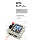
SS Geosub Pump & Controller Installation and Operation Manual Rev 7/25/2012 Part # 11200813 Table of Contents Section 1: System Description …………………………………………..…….. Section 2: System Installation …………………………………………….……. Section 3: System Operation ………………………………..………………… Section 4: System Maintenance ………………………………………….…… Section 5: System Troubleshooting ………………………….………………... Section 6: System Specifications ………………………………………….….. Section 7: Replacement Parts List …………………….…….………………… Warranty and Repair ……..…………………….……………..………………… 1 4 7 10 17 23 25 27 31 DOCUMENTATION CONVENTIONS This uses the following conventions to present information: An exclamation point icon indicates a WARNING of a situation or condition that could lead to personal injury or death. You should not proceed until you read and thoroughly understand the WARNING message. WARNING A raised hand icon indicates CAUTION information that relates to a situation or condition that could lead to equipment malfunction or damage. You should not proceed until you read and thoroughly understand the CAUTION message. CAUTION A note icon indicates NOTE information. Notes provide additional or supplementary information about an activity or concept. NOTE NOTICES In order to ensure that your Controller has a long service life and operates properly, adhere to the cautions below and read this manual before use. Disconnect from power source when not in use. Controller power input source must not exceed maximum ratings. Controller must be wired to a negative ground system. Controller may not operate properly with excess wiring not supplied by manufacturer. Avoid spraying fluid directly at controller. 2 Never submerge controller. Avoid pulling on wires to unplug controller wiring. Avoid using controller with obvious physical damage. To prevent controller damage, avoid dropping controller. The SS Geosub and SS Geosub Controller cannot be made dangerous or unsafe as a result of failure due to EMC interference. Do not operate this equipment if it has visible signs of significant physical damage other than normal wear and tear. Notice for consumers in Europe: This symbol indicates that this product is to be collected separately. The following apply only to users in European countries: This product is designated for separate collection at an appropriate collection point. Do not dispose of as household waste. For more information, contact the seller or the local authorities in charge of waste management. 3 Section 1: System Description Watt Controller Function and Theory This SS Geosub Controller is designed specifically for use with Geotech’s SS Geosub Pump. It provides a safe conditioned variable DC output power from an AC power source. Built-in sensing gives the operator accurate and precise control over the pump during sampling events. Efficient operation allows for extended field operation using portable AC generator equipment such as a gasoline powered generator. An average 1000 Watt gasoline powered generator with 1 gallon of gasoline can operate the SS Geosub Controller and SS Geosub sampling pump at full power for up to 18 hours. Be sure to read and understand your portable generator User Manual for proper installation operation, earth grounding instructions. An easy to use programmable user interface with bright display offers precise control over water flow during ground water sampling events. Site specific settings can easily be stored and recalled for repeatable efficiency during sampling events. Rugged construction and portability make connecting, installation and setup a breeze. The controller also includes a user activated dry run protection feature. Pump Function and Theory Geotech’s SS Geosub Pump is a fully submersible environmental pump designed specifically for use in ground water sampling. All wetted parts are made from high quality inert materials so sample integrity is not affected during sampling. The SS Geosub flow rate can be adjusted to change from well purge flow rates to low flow sampling rates. Figure 1-1 contains a graph for the flow rates and operating depths. Drop Tube Intake System Geotech’s optional Drop Tube Intake System allows you to easily relocate the pump intake well beyond the depth limitations of the pump. As long as the pump remains submerged, you can effectively and economically low flow a sample from a deeper point within the well’s screened section. See Figure 2-1. 4 Figure 1-1 Pump Chart Dry Run Feature Operation and Theory The dry run pump protection feature operates by measuring the output current level and comparing it to a user enterable set point. Many factors can influence the pump current draw, including head pressure, length of tubing and length of cable. Under all conditions, one thing remains the same: While pumping water, the pump draws higher current from the controller than when it is out of water and running dry regardless of other variables. Dry Run is intended for use in situations where flow rates are above .1 GPM (.38 LPM). Results using DRY RUN with lower flow rate are un-reliable. Pump Speed Control Operation and Theory Pump speed control is achieved by pressing the up or down button during run time. The number can be adjusted from 1 to 255 in increments of one unit. The adjustments can be made one at a time by pressing the or button once or can be changed rapidly by holding the or button. This number is representative of power output. Most conditions do not allow for the full 1 to 255 point range of use. At the upper end of the scale, the controller automatically prevents the user from overpowering a pump. The controller indicates when max 5 power has been reached and prevents the user from increasing the output further. In most cases, the usable range of control will be a 100 point window somewhere within the 1 to 255 point range. In general, the longer the cable being used the higher the speed set point and vice versa. Other application specific conditions such as head pressure and tubing size will also affect the speed set point window of operation. When adjusting the speed at the lower end of the 1 to 255 point scale, the pump may shut down. This fault condition is most obvious when a system has high flow, low pressure and long cable. OR Where #nn nn nnn DR = Well # = Time to reset dry well in minutes = Pump speed = Dry Run setting (ON/OFF) 6 Section 2: System Installation READ BEFORE PROCEEDING ANY FURTHER The SS Geosub Controller operates on high voltages supplied by a portable generator or grid-supplied main power. Care must be taken at all times to avoid electrical shock. Do not subject the SS Geosub Controller to contact with water. A grounding rod or stake driven directly into moist earth must be installed and electrically connected if using a portable generator larger than 2000 Watts. The SS Geosub Controller operation should be performed only by qualified persons. Reading this manual is essential for operating this equipment safely. If after reading this manual you are still unsure about the operation of this equipment contact Geotech for further information and training. The SS Geosub Controller stores energy for short periods even after power has been removed. The SS Geosub Controller has no field serviceable components and should never be opened by an unqualified person. The SS Geosub Controller has been specifically designed for use with Geotech’s SS Geosub Pump ONLY! Care must be taken when operating any equipment that operates on main voltage. Contact Geotech for service or repair. (See Section 5, System Troubleshooting, for common fault conditions and suggestions on how to correct issues). Verify intended power source matches the model supply specifications of the SS Geosub Controller in use. SS Geosub Controllers are available in 120VAC and 230VAC 50/60HZ and models and must be powered accordingly. Damage will result if controllers are connected to incorrect input power supply. Once input power source has been verified, connect input power cable to the SS Geosub Controller, and then connect cable to power source, i.e. portable generator or main grid power. 7 Connect input power cable. The display will light up, and after a short startup sequence is executed, a message will display indicating the controller status. Attach the pump to the controller using factory installed connectors on both the SS Geosub Controller and pump cable. Use of any other connectors or method of attaching pump to controller will cause shock and or fire hazard. When the status display shows “Main Menu” proceed to Section 3, System Operation. If display is blank, shows a fault or error condition, proceed to Section 5, System Trouble Shooting. Drop Tube Intake Assembly Installation and Operation The optional Drop Tube Intake Assembly is designed to allow you to relocate the SS Geosub Pump intake to a deeper screened part of the well. The SS Geosub Pump can either be built with a Drop Tube Intake and the necessary tubing length attached, or the Drop Tube Intake Assembly parts can be added to an existing pump at a later time. An example of all Drop Tube Intake parts can be found in Section 7. When using a Drop Tube Intake with your SS Geosub Pump, the pump must be placed below the static water line, as shown in Figure 2-1. Using a Drop Tube Intake can keep the pump at an optimum depth to maximize performance and the assembly is easily adaptable in the field. Drop Tube tubing lengths are custom to each well. When using or re-using poly tubing, it is suggested that small hose clamps be attached at the two hose barbs to prevent the accidental detachment of the drop tube assembly within the well. 8 Figure 2-1 SS Geosub Pump with Drop Tube Assembly in well 9 Section 3: System Operation Key Pad Description: This arrow is used to configure well option, raise the speed of the pump, and adjust settings in the program. This arrow is used to lower pump speed and adjust other settings of the program. This button will return you to the MAIN MENU from anywhere in the program. This button is used to start the pump, confirm selections and advance to the next section of the program. Basic Operation • • • • Plug power cord into controller. Plug power cord into AC supply outlet. Wait for initialization sequence to complete. From the MAIN MENU: • Press to start the pump with the default settings. • Wait for soft start sequence to complete. 10 • Press the rate. or buttons to adjust pump speed to achieve desired flow • Pump water at desired pump speed. • Press to stop and return to the MAIN MENU. Dry Run and Save Instructions • • • • Plug power cord into controller. Plug power cord into AC supply outlet. Wait for initialization sequence to complete. From the MAIN MENU: • Press to start the pump with the default settings. • Wait for soft start sequence to complete. • Press or buttons to adjust pump speed to desired point. • Press to toggle Dry Run (DR) ON or OFF. OR • Hold down the button for 3 seconds to enter the Dry Run Reset Time Change menu and Well Save menu. • Press or buttons to change 11 reset from dry run time between 0 and 60 minutes. • Press to advance to Well # Write menu. • Press or buttons to choose the well number in which you would like to save the new parameters in (up to 80 unique wells can be saved). • Press to save the new parameters that can be recalled under the selected well number at a later time. • Confirm overwrite by pressing the button. • Cancel overwrite by pressing the button. • Observe desired settings are displayed in the runtime display screen. Loading Saved Well • Plug power cord into controller. • Plug power cord into AC supply outlet. • Wait for initialization sequence to complete. • From MAIN MENU, press enter Load Well menu. to • Press or to select the well number and pre-set the parameters you would like to start pumping from. 12 • Press to load selected well parameters. • To cancel selection at any time, press • Press . to start pump with loaded well settings. Loading Well #0 will load the default start-up configuration. Customize Well Settings • Plug power cord into controller. • Plug power cord into AC supply outlet. • Wait for initialization sequence to complete. • From MAIN MENU, press go to Well Setup menus. to • Press or to select the desired pump speed setting. • Press • To Toggle OR • Press • Press or to select how long the controller waits to start pumping again 13 after dry run protection has been activated. • Press to save. • Press or to select the well number in which to save these parameters in. • Press . You will now be returned to the MAIN MENU screen. From here you can press the button to begin pumping at the settings just entered. Display Descriptions • MAIN MENU. Press button to start the pump with the default settings. • Press the button to load saved data from well number. • This message is shown after pressing the MAIN MENU. button from the • You can press to stop the pump and return to the MAIN MENU. • This message is shown after pressing the button in the MAIN MENU. You can use the or buttons to scroll through the well numbers from 0 to 80. The bottom line shows the parameters specific to the well number shown. Press load the chosen well parameters. 14 to • This message is shown after pressing to choose to load well # nn information. • This is the run time message shown during normal operation. Press or to adjust pump speed to desired set point. Press to change: OR Dry Run ON or OFF. Hold the button for 3 seconds to enter the Dry Run Reset Time Change and Well# Save menu to save the parameters. • Press to stop pumping and return to Main Menu. The lower left numbers are the pump speed point. The lower middle shows if Dry Run protection is ON or OFF. The lower right number is the time the controller will wait before resetting from a dry run detection fault. • This message is shown if during soft start no pump is detected. There are various reasons for this to happen. Check to see if the connector is secure and that the cable is not broken. • The following messages are shown during runtime if the pump speed set point is raised to an overload position or lowered to a minimum point to maintain proper flow. The controller will automatically detect when max or minimum output has been reached and prevent the user from increasing or decreasing the output further. • This message is shown during setup for adjusting the 15 time the controller waits to reset after a dry run fault has been detected. • This message displays when an entry has been changed but not saved to controllers’ memory for recall. • This message is shown when the pump is no longer submerged in water during normal run time operation mm:ss indicates the time left in minutes:seconds before pumping is restarted. If the pump is still not submerged the controller will restart the counter and return to this message. Press to manually override the Dry Run counter and return to normal run time operation. • This message is shown if the Dry Run counter has been manually overridden or when the operator has chosen to exit any runtime menu and is returning to the Main Menu. • This message is shown when there is a short circuit fault on the controller output. Check the cable and pump carefully for any damage that may have occurred. Refer to Section 5 for Troubleshooting. • This menu lets you choose in which well # to save the new parameters. • This menu asks you to confirm your choice to overwrite information currently stored in well # nn. 16 • May indicate major system fault. Disconnect power and allow controller to reset. If message should return, contact the Geotech service department. • When disconnecting power, it may take up to 2 minutes for complete shutdown. Section 4: System Maintenance All of the procedures called out within this section are provided by the Geotech Service Dept. Contact your nearest Sales Representative to have your SS Geosub Pump and Controller professionally inspected and serviced. Controller: Clean the controller as needed with mild soap and water on a cloth. Do not use abrasive cleaners or solvents. Do not spray with water or any other liquid or pressured solvents. Use an air source to blow water out of all cable connections as needed. Pump: Clean the pump between sampling events using detergent and water. Cleaning the pump between uses is important to keep the impeller from getting stuck in place, making it impossible to pump water. Fine grit and particulate matter can cause threads and tight fitting parts to become extremely difficult to disassemble if left to dry in the pump after use. The pump can be disassembled completely for decontamination and cleaning. The SS Geosub Pump must be thoroughly cleaned and dried between uses, especially prior to storage. Failure to thoroughly clean and dry the pump may result in corrosion and permanent damage to the equipment, making the pump unusable. Replacing the Gold Connectors From time to time it may become necessary to replace the male and female gold pin connectors within the SS Geosub Pump. This can be done as follows: For pin replacement kit, use Geotech P/N 51200092. Carefully remove the original shrink tubing from around the connectors and push the conductors out of the black plastic sleeves. 17 Cut the pins off each conductor at the base of the pin. Strip the insulation off the conductors 1/4” (6.3mm) back and tin the cable ends. Place the appropriate connector cover onto the cable ends before you solder on the new gold connectors (see visual aids for orientation). The curved side of the connector covers are to be towards the stripe wire side of the top cap and the red wire side of the control module. Attach the male gold pins to the conductors coming from the control module. Attach the female pins to the conductors coming from the top cap. Use the remaining 1/8” (3.175mm) of exposed wire to transfer heat for soldering the connector to the wire end. Avoid getting solder on the outside of the gold connector. Figure 2-2 After the gold connectors are soldered, slide the connector covers over the gold pins until they snap into place. The connectors should now look like Figure 2-3. 18 Figure 2-3 Once the connectors are attached and seated, cover the connectors with melt/seal heat shrink (1” (25.4mm) for the top cap cover, 1.5” (38.1mm) for the control module cover). Place the heat shrink so that it is flush with the outer edge of the control module connector and flush with the inner edge of the top cap connector. Too far out and the two connectors will not join properly. Figure 2-4 After the heat shrink is in place use a heat gun to form the heat shrink to the connector. Do not put the heat gun too close or apply heat for too long or the heat shrink and connector will melt. 19 Figure 2-5 While the heat shrink is still hot, pinch between the two conductors with a set of needle nose pliers to form a tight seal around both conductors. Using the melt/seal heat shrink will provide a seal to the connector. Figure 2-6 20 After all connections are properly covered with heat shrink you are now ready to reconnect your pump with the new connections. Figure 2-7 21 Replacing the SS Geosub Control Module or Motor Assembly From time to time it may become necessary to replace the SS Geosub Pump Control Module or Motor Assembly. Dismantle the SS Geosub Pump and disconnect the control module/motor assembly from the top cap. Remove the existing epoxy filled heat shrink between the control module and motor assembly. When removing heat shrink be careful to not damage the insulation on any wire. Using a soldering station, detach the motor assembly wires from the control module. Retrieve your new control module or motor assembly. (New assemblies come with heat shrink.) Slide the appropriate lengths of heat shrink over the black, white and red wires of the control module. Solder the control module to the motor assembly. Ensure that the connections are correct. If any two wires are swapped, the motor will run in the wrong direction. With the motor wires at bottom and facing you, attach the wires, left to right, as follows: Black wire connected to the left, white wire at center, and the red wire on the right. Figure 2-8 22 After all connections are soldered, slide over and apply the thinner heat shrinks to cover the three connections. (Figure 2-9) Figure 2-9 After the connections are covered, apply the larger piece of heat shrink to cover the three connections as a group. While the heat shrink is still hot, coil the bundle into a “pigtail” behind the motor (Figure 2-10) to make room for the assembly within the inner housing when re-assembled. Figure 2-10 Place the control module and motor assembly into the inner housing. Reconnect the top cap to the control module using the gold pin connectors. Fold the wire connection and insert the top cap into the inner housing, then slide the assembly into the outer housing and tighten the top cap to the outer housing. The Geosub pump is now ready for operation. 23 Section 5: System Troubleshooting DO NOT OPERATE THE SS GEOSUB CONTROLLER IF IT HAS BEEN DAMAGED, BROKEN, SMASHED OR EXCESSIVELY WORN. BROKEN COMPONENTS POSE A SEVERE THREAT TO THE SAFETY OF THE OPERATOR AND HIS OR HER ENVIRONMENT. CONTACT GEOTECH SERVICE AT 1-800-833-7958 FOR ANY SERVICE OR REPAIR NEEDS. Geotech’s SS Geosub Controller has been designed and manufactured to provide a long and trouble-free life under field use conditions. In general, the display will indicate any fault conditions that can occur during use. Problem: The display is not showing anything. Solution # 1: Verify the input power is correct and at the correct voltage. If unsure, have a qualified electrician verify main power source. Solution # 2: With the unit plugged in to a known good power source, and the pump attached, press the UP button. If the display has simply gone out: Lift the pump out of the well, if you hear a chirp sequence coming from the pump upon start up, followed by the sound of the impeller running, then the display needs to be replaced. Press the main menu key, deploy the pump and press the UP button again. Run the pump ‘blind’ using the up and down arrows to control flow. To stop the pump, use the main menu key. Contact Geotech Service to have the display repaired. Solution # 3: Disconnect the power cord from both the power outlet and the controller. Visually inspect the cord and plug ends for damage. If damaged, do not use. Visually inspect the power receptacle on the controller, if damaged do not attempt to repair. Contact Getoech Service for repairs. Problem: The display says “NO PUMP ATTACHED” Solution # 1 Unplug unit and wait 1-2 minutes, then restart. Solution # 2 If pump is submerged under a significant amount of water, program the controller to start at a higher pump speed set point. Solution # 3 Inspect the cable for damage and make sure the connections are secure inside the pump. Verify that everything is connected and there is no cable damage. Solution # 4 If using preset well settings, increase your pump start up set speed. For example if you had been trying a start up set speed of 30 try using 50 instead. 24 Problem: The display says “OUTPUT FAULT OVER CURRENT” Solution: Inspect the cable for damage. If no damage is found, disconnect the pump from the controller and press the button to start the pump. If the display says “OUTPUT FAULT” then the controller is internally damaged and must be returned to Geotech for repairs. If the controller display indicates “NO PUMP ATTACHED”, then the problem is in the cable or pump assembly and the controller is working. If there is no cable damage then the problem could be in the pump. Use an ohm meter to measure the input terminals to the pump. If the measurement is less than 100 ohms the potted control board inside the pump must be returned to Geotech Service for repair or replacement. If the measurement is greater than 100 ohms then inspect the motor assembly for bad bearings or debris preventing the impeller from turning. Problem: Pump impeller will not turn and controller indicates “NO PUMP ATTACHED” Solution: If mud, dirt or sand has dried onto the impeller, soak in water and try to remove debris. If the impeller is free of such debris then one of the bearings may be worn out and you must replace the motor/impeller assembly Geotech Part Number 51200089. 25 Section 6: System Specifications Controller specifications Model: IP rating: Watt SS Geosub Controller IP51 when open and operating. IP67 when closed. ATA 300 Maximum Input power 81200031: 130 Volts AC 2.6 amps nominal full load 115 Volts AC 50/60 HZ 310 Watts Maximum Input power 81200032: 250 Volts AC 1.3 amps nominal full load 230 Volts AC 50/60 HZ 300 Watts Controllers must be configured for either 110 or 230 Volts AC input at the factory. One or the other input voltages - not both! Output power: Variable 0 to 46 Volts DC at < 300 Watts Output power @ max voltage: 10 amps (max) Operating Temp: -20 to 100° Fahrenheit (-29 to 38°C) (Ambient air temperature) Humidity: Up to 90% humidity Weight: 16.45 lbs (7.46kg) Size: 16”L x 13”W x7”H (41cmL x 33cmW x 18cmH) Input protection: 5A CB 26 Pump specifications Electric Full Load Rating Maximum Amp Draw Overload 2/3 HP 35 amps Incorporated into SS Geosub controller Pipe Connection Discharge Port 1/4” female NPT (includes 3/8” hose barb) Operating Conditions Minimum Ambient Fluid Temperature Maximum Ambient Fluid Temperature 34°F (1°C) 176°F (80°C) Dimensions & Weight (Pump & Motor) Dimensions of pump Net Weight of pump w/o lead 12.2” L X 1.75” OD (31cmL x 4.5cmOD) 3.9 lbs (1.8kg) Weight of small Georeel with the following: • 100 feet (30.5m) of 12 AWG & safety cable • 150 feet (46m) of 12 AWG & safety cable • 200 feet (61m) of 12 AWG & safety cable 27 18.3 lbs (8.3kg) 21.6 lbs (9.8kg) 24.9 lbs (11.3kg) Section 7: Replacement Parts List Controller and Pump Assembly Replacement Part Numbers Part Description Part Number CORD,POWER,6'7" 12070014 CORD,POWER,230V,6' 11200850 SS GEOSUB CONTROLLER,CE,120V,120VAC INPUT,300W DC OUTPUT 81200034 SS GEOSUB CONTROLLER,CE,230V,230VAC INPUT,300W DC OUTPUT 81200035 MANUAL,SS GEOSUB CONTROLLER 11200813 ASSY,EXTENSION CORD FOR GEOSUB 15 FT 51201004 KIT,CONNECTOR,SS GEOSUB 51200092 SCREW,SS8,6-32 X 3/8 SHCS 12070039 O-RING KIT,SS GEOSUB 51200088 CHECK VALVE,SS GEOSUB,1/4"NPT 81200033 CABLE,12/2AWG,ETFE,SS GEOSUB WITH SS SAFETY CABLE 21200103 GEOREEL,HAND,SS GEOSUB,100' 81400143 GEOREEL,HAND,SS GEOSUB,150' 81400142 GEOREEL,HAND,SS GEOSUB,200' 81400141 GEOTECH,DC TO AC INVERTER,600W 81400127 1 2 3 4 5 6 7 8 9 10 11 SS Geosub Replacement Part Numbers Part Description BOLT,SS6,3/16-24,EYE,2" HOSEBARB,SS6,3/8 X 1/4 MPT CAP,SS6,TOP,SS GEOSUB CAP,SS6,O-RINGS,SS GEOSUB HOUSING,INNER,SS6,SS GEOSUB CONTROL MODULE,SS GEOSUB ASSY,MOTOR/IMPELLER,SS GEOSUB HOUSING,OUTER,SS GEOSUB,SS6 HOUSING,DROP TUBE,SS GEOSUB,SS6,3/8" NPT TUBING,PE,1/2 X 5/8,FT POLYETHYLENE ASSY,INTAKE,1.66,DROP TUBE 28 Part Number 17500406 17200357 21200076 21200121 21200072 51200083 51200089 51200186 51200187 87050504 51150071 Figure 7-1 SS Geosub Pump and Drop Tube Assembly 29 NOTES 30 NOTES 31 The Warranty For a period of one (1) year from date of first sale, product is warranted to be free from defects in materials and workmanship. Geotech agrees to repair or replace, at Geotech’s option, the portion proving defective, or at our option to refund the purchase price thereof. Geotech will have no warranty obligation if the product is subjected to abnormal operating conditions, accident, abuse, misuse, unauthorized modification, alteration, repair, or replacement of wear parts. User assumes all other risk, if any, including the risk of injury, loss, or damage, direct or consequential, arising out of the use, misuse, or inability to use this product. User agrees to use, maintain and install product in accordance with recommendations and instructions. User is responsible for transportation charges connected to the repair or replacement of product under this warranty. Equipment Return Policy A Return Material Authorization number (RMA #) is required prior to return of any equipment to our facilities, please call our 800 number for appropriate location. An RMA # will be issued upon receipt of your request to return equipment, which should include reasons for the return. Your return shipment to us must have this RMA # clearly marked on the outside of the package. Proof of date of purchase is required for processing of all warranty requests. This policy applies to both equipment sales and repair orders. FOR A RETURN MATERIAL AUTHORIZATION, PLEASE CALL OUR SERVICE DEPARTMENT AT 1-800-833-7958. Model Number: ________________ Serial Number: ________________ Date of Purchase: ________________ Equipment Decontamination Prior to return, all equipment must be thoroughly cleaned and decontaminated. Please make note on RMA form, the use of equipment, contaminants equipment was exposed to, and decontamination solutions/methods used. Geotech reserves the right to refuse any equipment not properly decontaminated. Geotech may also choose to decontaminate the equipment for a fee, which will be applied to the repair order invoice. 32 Declaration of Conformity Geotech Environmental Equipment Inc. 2650 E 40th Avenue Denver, CO 80205 Following products are covered: Geotech product PN: 81200031 Watt SS Geosub Controller 115 Volt 81200032 Watt SS Geosub Controller 230 Volt • Conforms with the principal safety objectives of the European Directive 73/23/EEC, [for UK only - as implemented by the Electrical Equipment (Safety) Regulations 1994], by application of the following standards: EN 61010 Year of affixation of the CE Marking: 2010 • Conforms with the protection requirements of the European Directive 89/336/EEC, [for UK only - as implemented by the Electromagnetic Compatibility Regulations 1992], by application of the following standards: EN 61326-1, emissions class A Signatory: Joe Leonard Product Development Year of manufacture: 2009 EMC conformity established 3/3/2010. This declaration is issued under the sole responsibility of Geotech Environmental Equipment Inc. 33 Geotech Environmental Equipment, Inc 2650 East 40th Avenue Denver, Colorado 80205 (303) 320-4764 ● (800) 833-7958 ● FAX (303) 322-7242 email: [email protected] website: www.geotechenv.com In the EU Geotech Equipos Ambientales S.L. Abat Escarré # 12 Mollet del Valles, Barcelona 08100, España Tlf: 93 5445937 email: [email protected] website: www.geotechenv.com/spain.html