1
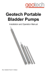
Geotech
Portable Bladder Pumps
Installation and Operation Manual
Rev 05/20/2011 Part# 11150323
TABLE OF CONTENTS
DOCUMENTATION CONVENTIONS...........................................................................................2
CHAPTER 1: SYSTEM DESCRIPTION ......................................................................................4
FUNCTION AND THEORY .................................................................................................4
SYSTEM COMPONENTS: .................................................................................................5
SYSTEM OPERATION:.......................................................................................................5
CHAPTER 2: SYSTEM MAINTENANCE ....................................................................................8
CHAPTER 3: SYSTEM SPECIFICATIONS...............................................................................10
CHAPTER 4: REPLACEMENT PARTS LIST............................................................................12
THE WARRANTY .......................................................................................................................20
EQUIPMENT RETURN POLICY................................................................................................20
EQUIPMENT DECONTAMINATION..........................................................................................20
DECLARATION OF CONFORMITY ......................................................................................Back
DOCUMENTATION CONVENTIONS
This manual uses the following conventions to present information:
An exclamation point icon indicates a WARNING of a situation or condition that
could lead to personal injury or death. You should not proceed until you read
and thoroughly understand the WARNING message.
WARNING
A raised hand icon indicates CAUTION information that relates to a situation or
condition that could lead to equipment malfunction or damage. You should not
proceed until you read and thoroughly understand the CAUTION message.
CAUTION
A note icon indicates NOTE information. Notes provide additional or supplementary information about an activity or concept.
NOTE
2
In order to ensure that your pump has a long service life and operates properly, adhere to
the cautions below and read this manual before use.
For long term storage greater than 1 week, care should be taken to clean and dry all pump
components. This will help with long term reliability. An inert lubricant can be used on the
o-ring seals to promote longevity and elasticity.
Pump operation and decontamination should be performed to your standard operating
procedures.
Operation of system utilizing non-Geotech OEM parts could result in equipment failure or
malfunction. This includes air and fluid tubing.
Avoid operating the system without securely anchoring safety cable attached to down
well components.
Always wear gloves and be mindful of contaminated fluids contacting your person and entering
the environment when operating any ground water sampling device.
Do not operate this equipment if it has visible signs of significant physical damage other than
normal wear and tear.
Notice for consumers in Europe:
This symbol indicates that this product is to be collected separately.
The following apply only to users in European countries:
• This product is designated for separate collection at an appropriate collection point.
Do not dispose of as household waste.
• For more information, contact the seller or the local authorities in charge of waste
management.
3
Chapter 1: System Description
Function and Theory
Geotech’s pneumatic Portable Bladder Pumps operate with a unique action, ideal for both gentle low-flow sampling and high flow rate purging. Timed on/off cycles of compressed air alternately squeeze the flexible bladder to displace water out of the pump to the surface and
exhaust allowing the pump to refill.
Fluid enters the pump through the fluid inlet check valve at the bottom of the pump body, via
hydrostatic pressure (automatically by submergence). As a result, the entire pump MUST be
submerged to operate. Next, the internal part of the bladder fills with fluid. Compressed air enters the space between the bladder and the interior of the pump housing. The inlet check valve
closes and the discharge check valve (top) opens. Compressed air squeezes the bladder,
pushing the fluid to the surface. The discharge check valve prevents back flow from the discharge tubing as the inlet check valve opens again to fill the pump. Therefore, the discharge
check valve engages during the fill cycle and disengages during the exhaust cycle. Driven by
the GEOCONTROL PRO or GEOCONTROL II, this cycle automatically repeats.
An optional drop tube can be used to sample from depths below the specified maximum sampling depth. The drop tube assembly connects a remote intake to the pump through a tube
connected to the pump inlet. The intake depth can be any custom length of tubing. The pump
assembly itself must still be submerged below the water level. This means the depth to water
cannot exceed the maximum pumping depth of the pump.
Note: Compressed air does not contact the sample. The bladder prevents contact between
the pump drive air and the sample.
Be sure to read and understand your portable generator and/or portable air compressor user
manual for proper installation and operation and Earth grounding instructions. If using portable
compressed gas tanks, be sure to exercise proper caution, use safety protection devices as
outlined by the supplier, and observe any additional safety requirements mandated by local jurisdiction.
4
System Components:
Geotech’s Portable Bladder Pumps consist of four components as follows:
(1)
(2)
(3)
(4)
(5)
Bladder Assembly
External Pump Housing
Internal Tube Assembly
Inlet Screen Assembly
Optional Drop Tube Intake Assembly
System Operation:
The user must determine site specific parameters such as water level, recharge rate and adherence to low flow purging guidelines.
READ BEFORE PROCEEDING ANY FURTHER
Before deploying any sampling pump, secure a safety cable to an anchoring point at or near
the well head to the pump.
Geotech Portable Bladder Pumps can be operated using a variety of controllers. Be sure to
consult the user guide specific to the controller you are using.
The Geotech Portable Bladder Pump requires two tubing lines. One of the lines is used for the
air supply and exhaust. The second line is used for discharge fluid. See the system specifications section of this manual for tubing sizes. When using the 1.66" (4 cm) diameter pump, the
larger diameter tube is for fluid and the smaller one for air.
If a Drop Tube Intake assembly is employed, a third tubing line is necessary.
On the .675" (1.7 cm) and .85" (2 cm) diameter pumps, both air and fluid lines are the same
size. The letter “A” has been stamped near the hose barb on the top of the pump. This indicates the air supply and exhaust line barb. The remaining barb is for the discharge fluid line.
5
Failure to attach air and fluid lines to the appropriate ports could result in damage to the
bladder.
Use of an air source and controller not supplied by Geotech could result in pressure buildup
and unexpected pressure storage in the pump and airline. Therefore, operation of the pump is
not recommended with equipment other than that provided by Geotech.
Once tubing and safety cable are in place, slowly deploy the pump, screen first, into the well.
If depth to water is known, a mark can be placed on the tubing to indicate when the pump has
reached the desired level. To operate as designed, the pump should be fully submerged. Optimal pump performance is achieved with submergence of greater than 10 feet of water column.
Less submergence could result in reduced pumping performance depending on type of fluid*
being pumped and physical condition of the bladder. Older, worn bladders can develop a
shape memory and may not be able to fill completely without sufficient submergence. In any
case, pumping will still be achieved and the sampling event can be completed.
A thin, less rugged bladder could fill more easily in lower submergence applications. Geotech
has chosen to implement the use of more reliable heavy walled Poly or robust PTFE material to
accommodate longer life of the bladder and overall reliability of the pump.
* Designed for pumping groundwater only, other fluids at user’s risk.
6
Once the pump is at the desired level within the well bore, set the controller timers to pressurize and exhaust. These settings should be such that the bladder is never over compressed. A
good rule of thumb is to set the pressure cycle so that the fluid stream exiting the fluid line just
starts to fall off when the Discharge/Charge timer expires. If the controller being used has a
pressure gauge, you will notice the pressure level will climb and then ‘stall out’ during pumping
and start to ‘climb’ after all of the water has been evacuated from the pump. If you notice the
pressure climbing after a pump cycle, reduce the pressurization time.
Using the volume per cycle specifications guide in this manual, set the exhaust/delay time to
optimize the amount of fluid discharged during the pressure cycle.
Both fill/exhaust times and discharge/pump times will vary depending on submergence, depth
to water, tubing size and overall tubing length.
For deployment of optional Drop Tube Assembly attach desired length of drop tube to the intake hose barb and hose barb on bottom of pump. Send the drop tube intake down the well
followed by the drop tube tubing, then the pump and finally the air and fluid discharge lines.
More information can be found in the user manual specific to the controller you are using.
7
Chapter 2: System Maintenance
Bladder Removal Steps:
Remove the lower Teflon® compression ring
(#21150042) by pulling off end of the internal
center tube assembly (#21150091).
Pull the lower end of the bladder towards the
middle of the internal center tube assembly
and remove O-ring (#11150319) from the
lower end of the tube.
Remove the upper Teflon® compression ring
(#21150042) and slide the ring off of the end
of the internal center tube assembly
(#21150091).
Slide the bladder (#21150054) off of the
internal center tube weldment assembly
(#21150091).
Note: Part numbers listed in the assembly procedure described above pertain only to the 1.66
Portable Bladder Pump. The .675 and .850 Portable Bladder Pumps assemble similarly, however, with different part numbers which can be found in the following sections.
Note: SS Ball must be
inside Intake Assembly.
This configuration may
damage pump.
8
Reassembly Steps:
Install O-ring (#11150319) to upper end of the
center tube weldment assembly (#21150091).
Slide bladder (#21150054) onto the center
tube assembly and over the O-ring
(#11150319) on the upper end of the center
tube assembly. Be careful not to roll the Oring when sliding the bladder over this end.
Slide a Teflon® compression ring (#11150042)
over the bladder and push down over bladder
and upper end of the center tube.
With the upper end of the bladder secured by
the Teflon® compression ring, slide the second
compression ring over the bladder about midway down the assembly.
Slide the bladder up, beyond the bottom of
the center tube assembly, exposing the lower
end of the center tube and install the O-ring
(#11150319) into the groove on the lower end.
Slide the bladder back down over the O-ring
being careful not to roll the O-ring.
Now slide the Teflon® compression ring over
the bladder until it seats flush with the bottom
of the center tube assembly.
Replace the outer housing (21150041). Be
sure the outer housing is sealed against the
upper cap.
Replace the bottom intake assembly
(51150067) by screwing it into the bottom of
the pump. There shouldn't be any gaps between the outer housing and top or bottom
caps.
Inspect O-rings and bladder for damage.
Replace if torn, ripped or excessively worn.
9
Chapter 3: System Specifications
1.66 Portable
.850 Portable
.675 Portable
Pump Housing
316 SS
316 SS
316 SS
Pump Ends
316 SS
316 SS
316 SS
Bladder Material
Virgin PTFE
Virgin PTFE
Virgin PTFE
Outer Diameter
1.66" (40 mm)
.850" (21.6 mm)
.675" (17 mm)
Length w/Screen
19" (48 cm)
18 5⁄ 8" (47 cm)
18 3 ⁄4" (47.625 cm)
Weight
3.0 lbs. (1.36 kg)
1.1 lbs. (500 g)
.83 lbs. (376 g)
Volume/Cycle
5 oz. (150 mL)
1 oz. (29 mL)
.5 oz. (15 mL)
Min. Well I.D.
2" (50 mm)
1" (25 mm)
.75" (19 mm)
Max. Operating Pressure
100 psi (7 bar)
100 psi (7 bar)
100 psi (7 bar)
Min. Operating Pressure
5 psi (ash)* (.3 bar)
5 psi (ash)* (.3 bar)
5 psi (ash)* (.3 bar)
Max. Sampling Depth
200' (61 m)
200' (61 m)
200' (61 m)
.17" ID x .25" OD
.17" ID x .25" OD
.17" ID x .25" OD
(4 mm ID x 6 mm OD)
(4 mm ID x 6 mm OD)
(4 mm ID x 6 mm OD)
.25" ID x .375" OD
(6 mm ID x 9.5 mm OD)
.17" ID x .25" OD
(4 mm ID x 6 mm OD)
.17" ID x .25" OD
(4 mm ID x 6 mm OD)
Tubing Size
Air
Discharge
*ash = above static head
Model: All Portable Bladder Pumps discussed in this manual have the same general
specifications.
IP rating: (NA) Submersible to 500 feet (152 m) of water column.
Altitude: 9000 feet (2.75 km) above sea level.
Special air source considerations need to be taken into account 9000 feet (2.75 km) above
mean sea level (AMSL).
10
Operating Temp: 32 (0°C) to 212 (100°C) degrees Fahrenheit ambient air or fluid temperature.
Special care must be taken to avoid burns and exposure to out-gassing of volatiles when
pumping fluids at elevated temperatures.
Weight: See individual pump listings above.
Size: See individual pump listings above.
Humidity: (NA)
11
Chapter 4: Replacement Parts List
MODEL 1.66 PORTABLE BLADDER PUMP CE – 81150034
Item
Description
Part No.
1
BLADDER, PTFE, 1.66 PORTABLE
21150054
§
BLADDER, PE, 1.66 PORTABLE, EA
21150055
§
BLADDER, PE, 1.66 PORT, 12PK
21150056
2
1
HOUSING, SS6, 1.66, PORTABLE BP
21150041
3
1
HOSEBARB, SS6, MOD, 1/4 X 1/4 MPT MODIFIED DISCHARGE 11150106
4
1
HOSEBARB, SS6, .170 X 1/8 MPT AIR LINE
21150019
5
2
RING, COMPRESSION, PTFE 1.66 BP, CE PORTABLE
21150042
6
1
BALL, SS6, 3/8"
17500081
7
2
O-RING, VITON, 2.5MM X 23MM
11150319
8
2
O-RING, VITON, 2.5MM X 36MM
11150318
9
1
ASSY, HANGER, 166, PBP, SFTY CB, CE
51150068
10
1
CAP UPPER WELDMENT, SS, 1.66, PBP CE
21150091
11
1
PLUG, BALL RETAINER, 1.66 PBP CE
21150096
12
1
O-RING, VITON, #014
17500119
13
1
BALL, SS6, 1/2"
17500082
14
1
ORING, VITON, 2MM X 20MM
11150332
15
1
CAP LOWER, SS, 1.66, PRTBL BP, CE
21150094
16
1
SCREEN, INTAKE, 1.66, SS6, PBP, CE
21150095
17
1
DISC, PTFE, 1.66, PBP PORTABLE
21150043
18
1
RING, SNAP, SS6, INTERNAL, 1.66 BP PORTABLE
11150051
19
1
ASSY, BOTTOM INTAKE 1.66 PBP, CE
51150067
20
§
ASSY, LOWER CAP, 1.66 PBP, DROP TUBE, CE
51150128
21
1
DROP TUBE, CAP LOWER, 1.66 PBP, CE SS
21150098
22
2
HOSEBARB, SS6, 3/8 X 3/8 MPT
16600213
23
§
TUBING, PE, 3/8 X 1/2, FT POLYETHYLENE
87050503
24
§
ASSY, INTAKE, 1.66 PBP, DROP TUBE, CE
51150071
25
1
INTAKE, DROP TUBE, 1.66 PBP, DROP TUBE, CE
21150113
1
MANUAL, PBP, CE
11150323
§
SPARE PARTS KIT, 1.66, PBP, CE
[Items 5 (2), 6, 7 (2), 8 (2), 12, 13, 14, 16, 17, 18]
51150066
§
KIT, 1.66 PBP, O-RING SET, CE O-RING SERVICE KIT
[Items 7 (2), 8 (2), 12, 14]
91150012
1
Qty
§ = Sold Separately
1.66 Portable Bladder Pump Service Kits
If pump purchased before 10/18/10, you can access the legacy manual part number 11150272 on our
website at www.geotechenv.com or contact Geotech directly for more information.
12
1.66 Portable Bladder
Pump Components
3
4
9
6
10
8
5
7
Pump
Assembly
2
1
Bladder
Assembly
7
5
Housing
11
11
12
12
13
13
14
14
20
8
8
15
21
19
22
16
23
Optional
Drop Tube
Assembly
17
22
18
25
24
16
17
18
13
MODEL .85 PORTABLE BLADDER PUMP CE – 81150115
Item
Description
Part No.
1
BLADDER ,PTFE, .85 PORTABLE BP
51150051
§
BLADDER, PE, .85" PORTABLE BP, EA
21150100
§
BLADDER, PE, .85 PORT, CE, 12PK
21150099
2
1
HOSEBARB, SS6, MOD, .170 X 1/8 NPT DISCHARGE
11150118
3
1
HOSEBARB, SS6, .170 X 10/24 AIR
17200245
4
2
BALL, SS6, 1/4"
17500079
5
1
CAP UPPER WELDMENT, SS6, .85 BP PORTABLE
21150045
6
2
RING, COMPRESSION, PTFE, .850, CE, PORTABLE BP
21150048
7
2
O-RING, VITON, CS .0629, ID 17.1MM
17500112
8
4
O-RING, VITON, #012
17500111
9
1
HOUSING, SS6, .850, PORTABLE BP
21150047
10
1
ASSY, BOTTOM INTAKE, .85 PBP PORTABLE
51150118
11
1
CAP, LOWER, SS6, .850, PORTABLE BP
21150046
12
1
SCREEN, INTAKE, SS6, .85 PORT BP PORTABLE
21150050
13
1
DISC, PTFE, .85 PBP PORTABLE
21150049
14
1
RING, SNAP, SS6, INTERNAL, .85 BP
11150053
15
§
ASSY, LOWER CAP, .850 PBP, DROP TUBE, CE
51150129
16
1
DROP TUBE, CAP LOWER, .850 PBP, CE SS
21150109
17
2
HOSEBARB, SS6, 1/4 X 1/8 MPT
17200072
18
§
TUBING, PE, 1/4 X 3/8, FT POLYETHYLENE
87050502
19
§
ASSY, INTAKE, .850 PBP, DROP TUBE CE
51150069
20
1
INTAKE, DROP TUBE, .850 PBP, CE, SS
21150111
1
MANUAL, PBP, CE
11150323
§
SPARE PARTS KIT, .85, PBP, CE
[Items 4 (2), 6 (2), 7 (2), 8 (4), 12, 13, 14]
51150123
§
KIT, .85 PBP, O-RING SET, CE, O-RING SERVICE KIT
[Items 7 (2), 8 (4)]
91150013
1
Qty
§ = Sold Separately
14
.850 Portable Bladder Pump Components
2
3
4
5
6
7
8
Housing
9
Center Tube
Assembly
Bladder
Assembly
1
7
15
16
17
8
6
18
Optional
Drop Tube
Assembly
17
8
7
11
20
19
10
12
12
13
13
14
14
15
Intake
Assembly
MODEL .675 PORTABLE BLADDER PUMP CE – 81150117
Item
Description
Part No.
1
BLADDER, PTFE, .675, PBP, CE
51150126
§
BLADDER, PE, .675 PORTABLE, EA
21150102
§
BLADDER, PE, .675 PORT, CE, 12PK
21150101
2
1
HOUSING, SS6, .675, PORTABLE BP
21150032
3
2
HOSEBARB, SS6, .170 X 10/24 AIR
17200245
4
1
WELDMENT, INNER, SS6, .675 PBP
51150125
5
2
O-RING, VITON, #014
17500119
6
2
O-RING, VITON, #107
17500604
7
2
RING, COMPRESSION, PTFE, .675 PORTABLE BP, CE 21150106
8
1
O-RING, VITON, #009
17500113
9
1
ASSY, BOTTOM INTAKE, .675", PBP
51150120
10
1
RETAINER, BALL, .675 PBP, TACO
21150087
11
1
BALL, SS6, 1/4"
17500079
12
1
CAP, LOWER, SS6, .675 BP
21150031
13
1
SCREEN, INTAKE, SS6, .675 PBP
11150317
14
1
DISC, PTFE, .675 BP
21150033
15
1
RING, SNAP, SS, .675 PBP
11150182
16
§
ASSY, LOWER CAP, .675 PBP, DROP TUBE, CE
51150130
17
1
DROP TUBE, CAP LOWER, .675 PBP, CE SS
21150110
18
2
HOSEBARB, SS6, 1/4 X 1/8 MPT
17200072
19
§
TUBING, PE, 1/4 X 3/8, FT POLYETHYLENE
87050502
20
§
ASSY, INTAKE .675 PBP, DROP TUBE CE
51150070
21
1
INTAKE, DROP TUBE, .675 PBP, CE, SS
21150112
1
MANUAL, PBP, CE
11150323
§
SPARE PARTS KIT, .675, PBP, CE
[Items 6 (2), 7 (2), 8 (2), 9, 11, 12, 14, 15, 16]
51150124
§
KIT, .675 PBP, O-RING SET, CE O-RING SERVICE KIT
[Items 6 (2), 7 (2), 9]
91150014
1
Qty
§ = Sold Separately
16
.675
Portable
Bladder Pump
Components
3
4
5
6
7
Center Tube
Assembly
1
Bladder
Assembly
Housing
2
5
10
11
17
16
18
7
6
Optional
Drop Tube
Assembly
19
8
5
18
10
11
21
12
9
Intake
Assembly
13
20
13
14
14
15
15
17
System Troubleshooting:
Be sure to read and understand your portable generator and/or portable air compressor user
manual for proper installation and operation and Earth grounding instructions. If using portable
compressed gas tanks be sure to exercise proper caution and safety protection devices as outlined by the supplier and any additional safety requirements mandated by local jurisdiction.
DO NOT OPERATE THIS EQUIPMENT IF IT HAS BEEN DAMAGED, BROKEN, SMASHED OR
EXCESSIVELY WORN. BROKEN COMPONENTS POSE A SEVERE THREAT TO THE SAFETY
OF THE OPERATOR AND HIS OR HER ENVIRONMENT. CONTACT GEOTECH FOR ANY
SERVICE OR REPAIR NEEDS.
Problem: Air in fluid line or flow cell.
Solution: Ensure timer settings on controller are such that the bladder is not being over pressurized. Verify Teflon® collar is in place at either end of the bladder. Inspect o-rings for damage
and replace if needed. Inspect bladder for cuts and holes and replace if needed.
Occasionally, significant amounts of dissolved gasses can be encountered in ground water.
Especially in deep well areas with significant hydraulic pressures. When this fluid is exposed to
atmosphere out-gassing may occur. Refer to your SOP for specifics on dealing with this situation.
Problem: Not pumping any fluid (and no air either).
Solution: Verify the pump is below static water level. Inspect air line tubing for kinks, cracks or
breaks. Make sure you are not getting leaks at any fittings. Replace damaged or worn tubing.
Cut tubing back and re-terminate at leaking fitting joint.
Problem: Not pumping any fluid (air is coming out fluid discharge line).
Solution: Disassemble pump and inspect the o-rings and bladder. Replace either or both if
damaged. Verify the pump is below static water level.
18
Notes:
19
THE WARRANTY
For a period of one (1) year from date of first sale, product is warranted to be free from defects
in materials and workmanship. Geotech agrees to repair or replace, at Geotech’s option, the
portion proving defective, or at our option to refund the purchase price thereof. Geotech will
have no warranty obligation if the product is subjected to abnormal operating conditions, accident, abuse, misuse, unauthorized modification, alteration, repair, or replacement of wear parts.
User assumes all other risk, if any, including the risk of injury, loss, or damage, direct or consequential, arising out of the use, misuse, or inability to use this product. User agrees to use,
maintain and install product in accordance with recommendations and instructions. User is
responsible for transportation charges connected to the repair or replacement of product
under this warranty.
Equipment Return Policy
A Return Material Authorization number (RMA #) is required prior to return of any equipment to
our facilities, please call 800 number for appropriate location. An RMA # will be issued upon
receipt of your request to return equipment, which should include reasons for the return. Your
return shipment to us must have this RMA # clearly marked on the outside of the package.
Proof of date of purchase is required for processing of all warranty requests.
This policy applies to both equipment sales and repair orders.
FOR A RETURN MATERIAL AUTHORIZATION, PLEASE CALL OUR SERVICE DEPARTMENT AT
1-800-833-7958
Model Number: _____________________________________________________
Serial Number: _____________________________________________________
Date of Purchase: _____________________________________________________
Equipment Decontamination
Prior to return, all equipment must be thoroughly cleaned and decontaminated. Please make
note on RMA form, the use of equipment, contaminants equipment was exposed to, and
decontamination solutions/methods used.
Geotech reserves the right to refuse any equipment not properly decontaminated. Geotech
may also choose to decontaminate equipment for a fee, which will be applied to the repair
order invoice
20
Declaration of Conformity
Geotech Environmental Equipment Inc.
2650 E 40th Avenue
Denver, CO 80205
Following products are covered:
Geotech product PN
81150034 1.66 PORTABLE BLADDER PUMP CE
81150115 .85 PORTABLE BLADDER PUMP CE
81150117 .675 PORTABLE BLADDER PUMP CE
• Conforms with the principal safety objectives of the European Directive 73/23/EEC, [for UK
only - as implemented by the Electrical Equipment (Safety) Regulations 1994], by application
of the following standards: EN 61010 Year of affixation of the CE Marking: 2010
• Conforms with the protection requirements of the European Directive 89/336/EEC, [for UK
only - as implemented by the Electromagnetic Compatibility Regulations 1992], by application
of the following standards: EN 61326-1, emissions class A.
Signatory:
Joe Leonard
Product Development
Year of manufacture: 2010
EMC conformity established 3/3/2010.
This declaration is issued under the sole responsibility of
Geotech Environmental Equipment Inc.
Model ___________________________________________________
Serial Number ____________________________________________
Geotech Environmental Equipment, Inc.
2650 East 40th Avenue • Denver, Colorado 80205
(303) 320-4764 • (800) 833-7958 • FAX (303) 322-7242
email: [email protected] website: www.geotechenv.com
In the EU
Geotech Equipos Ambientales S.L.
Abat Escarré # 12 Mollet del Valles, Barcelona 08100, España
Tlf: 93 5445937
email: [email protected] • website: www.geotechenv.com/spain.html
Printed in the United States of America
Rev. 05/20/2011 Part #11150323