1
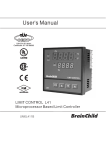
ezeio™ Controller and
the 2400-A16 input expansion.
Important Supplementary Manual to be read in conjunction with the
eze User Manual: http://ezesys.com/manual
ezeio Controller and the 2400-A16 input expansion Manual Index.
Product Liability.
Description.
Ordering Information.
ezeio Controller Compatibility with Intech Micro Stations.
ezeio Ethernet TCP/IP Connection.
Using a data GSM/3G SIM in the ezeio-GSM Controller.
Section 1 - ezeio Controller.
Configuring the ezeio Controller local inputs.
Getting started with configuration.
Easy steps for Calibration.
Section 2 - 2400-A16.
Intech Micro 2400-A16 Station
Adding a 2400-A16 station to an ezeio Controller.
Getting started with configuration.
Configuring the ezeio Controller.
Example 1: eze temperature input scaling for RTD’s and thermocouples.
Example 2: For all other analogue values the 2400-A16 outputs to eze...
Example 2.1: Analogue Flow meter.
Example 2.2: Analogue Pressure sensor.
Example 2.3: Digital Flow Meter.
Example 2.4: State On/Off.
On Site Calibration Trim.
Section 3 - Alarms.
Page 2
Page 3
Page 3
Page 3
Page 3
Page 4
Page 5
Page 5
Page 5
Page 6
Page 8
Page 8
Page 8
Page 9
Page 10
Page 11
Page 12
Page 12
Page 13
Page 14
Page 15
Page 15
Page 16
Note: The eze System uses US English, so some spelling/terminology differs.
ezeio™ is a trademark of eze System, Inc.
Please Note: Intech Instruments Ltd are the New Zealand representative for eze System, Inc products. Please contact
the eze System representative in your country if you require sales or service support for eze System, Inc products.
Product Liability. This information describes our products. It does not constitute guaranteed properties and is not intended to affirm the suitability of a
product for a particular application. Due to on-going research and development, designs, specifications, and documentation are subject to change
without notification. Regrettably, omissions and exceptions cannot be completely ruled out. No liability will be accepted for errors, omissions or
amendments to this specification. Technical data are always specified by their average values and are based on Standard Calibration Units at 25C,
unless otherwise specified. Each product is subject to the ‘Conditions of Sale’.
Warning: These products are not designed for use in, and should not be used for patient connected applications. In any critical installation
an independent fail-safe back-up system must always be implemented.
2
ezeio™ Controller and the
4 Analogue Inputs.
Interface with 2400-A16 for Input Expansion.
Internet Based Setup and Monitoring.
2400-A16 input expansion.
Description.
The ezeio™ Controller comes ready to start monitoring,
logging and controlling over the Internet.
As soon as the controller is connected to power and an
Internet connection, it will start communicating with the
eze System servers. There is no need for special
software or network setup. The ezeio connection is
encrypted, bi-directional and very efficient.
ezeio™ Controller and the 2400-A16 input expansion.
Ordering Information.
ezeio-STD
ezeio-GSM
ezeio Controller with Ethernet port, 4 analogue inputs and Modbus-RTU RS-485 Comms.
ezeio Controller with GSM/3G transceiver, Ethernet port, 4 analogue inputs and Modbus-RTU
RS-485 Comms.
ezeio Controller Compatibility with Intech Micro Stations.
The Modbus-RTU RS-485 port on the ezeio controller can be used to connect to Intech Micro Stations: 2400-A16,
2400-M-R and 2100-A16. This allows the controller to be expanded to log up to 40 channels max per ezeio controller.
If additional relay outputs are required, the 2400-R2 can be connected to the 2400-A16 for relay expansion - refer to the
2400-A16 Installation Guide for more information.
ezeio Ethernet TCP/IP Connection.
Ensure that you connect the Ethernet cable with the Ethernet port on the ezeio controller only. Do NOT plug into the
Modbus 485 port.
Typically the ezeio controller should automatically connect once plugged into the Ethernet TCP/IP network. You may
need to power cycle the ezeio (turn the power off/on).
See pages 11/12 of the ezeio User Manual for Ethernet TCP/IP connection information: http://ezesys.com/manual
Please note that Intech will not be able to help with the setup and operation of an Ethernet TCP/IP network and
assigning of IP addresses.
3
Using a data GSM/3G SIM in the ezeio-GSM Controller.
This section is for the ezeio-GSM controller model only.
1. Obtain a data GSM/3G SIM with no password. (Note: the ezeio-GSM controller takes a standard size SIM card.)
2. Place SIM in a mobile phone to activate as per the providers instructions, or get the provider to do this at the time of
purchase.
3. Place the SIM in the ezeio-GSM Controller with the chisel edge of the SIM at the top left (as shown circled below).
4. Follow the instructions in the ezeio-GSM Controller Instruction Manual starting page 21.
5. Connect via Ethernet and login to www.ezecontrol.com
6. In the eze Configuration area, click on “System”:
Setting required for New Zealand - GPRS APN (leave all other areas blank) - match to your provider as listed below:
Vodafone APN:
vodafone
Spark (was Telecom) APN:
internet
2degrees APN:
internet
7. Click ‘Save changes’. Remove the Ethernet connection and turn the Power off/on. Check that a connection via
GSM/3G has been established in the eze System.
If you are outside New Zealand please contact your local GSM/3G provider for the data GSM/3G SIM and the APN
settings needed.
Note: Initial connection via Ethernet is required for ezeio setup before the GSM/3G connection can be used.
Important: We strongly recommend having the data GSM/3G SIM on account.
Using Prepay will result in no connection if the credit runs out (if this happens, then once more credit has been
added, the eze system will need to have the power turned off/on in order to re-establish a connection).
This is not an issue with on account data plans.
GSM/3G Network Coverage:
For GSM/3G connection, the ezeio-GSM needs to be within the network coverage area where it will be used. Check on
your GSM/3G providers website for their network coverage maps.
Please note that Intech is unable to guarantee connection, even if the ezeio-GSM is within the network coverage
area.
4
Section 1 covers the ezeio Controller 4 local inputs, and Section 2 covers adding the power of the 2400-A16, to
expand the inputs up to 40, plus adding more outputs.
Section 1 - ezeio Controller.
Configuring the ezeio Controller local inputs.
The ezeio™ controller has four standard inputs. Each input may be configured individually in one of the four ways
described here:
Jumper setting
Description
0~5Vdc.
Input impedance is >70kOhm.
Raw reading is about 10000 at 5.0V (0.5V per count).
0~10Vdc.
Input impedance is >70kOhm.
Raw reading is about 10000 at 10.0V (1mV per count).
0~30mA (suitable for 4~20mA transducers).
An internal 100 Ohm resistor connects the input terminal to Common.
Raw reading is about 10000 at 30mA (3uA per count).
Contact, Pulse or Resistive (0~50Ohm).
An Internal 10K resistor will hold the input to 5V.
This is the factory default setting.
4~20mA
Resistance or
Pulse input
To access the input jumper settings, open the ezeio™ by removing the four black screws.
Read the eze User Manual pages 13 through to and including page 16, covering input connections.
http://ezesys.com/manual
Getting started with configuration.
Go to www.ezecontrol.com
Enter your Account number, Login and Password.
Click on the ‘Configure’ tab
And then the + by the Inputs:
Now select which input you wish to configure. Select the
‘Input type’ to match the configuration of the ‘Jumper’
setting in the table above. Always remember to select
‘Save Changes’ after making a change.
Important Note: The analogue inputs have a nominal
calibration only (ex factory), and where accuracy is
required, individual calibration of each channel is
required. This is done with the use of an accurate signal
calibrator.
5
Easy steps for Calibration.
1. As an example: on the ezeio Controller Input 2, the analogue input is set to 0~10Vdc. Apply an accurate 10Vdc
signal to this input and on the eze ‘Status Page’, note the ‘Raw’ reading on channel 2.
In this example below the Raw reading = 9798.
2. Now go to the eze Configure page and click on ‘Input type’ and select ‘Custom’ as shown.
Note: Do not use the percentage symbol in the
‘Input name’ and ‘Unit’ text boxes, as this will result in
an error.
3. Now click on ‘Linear analog’ and enter the values as shown next:
Point 1 and Point 2 are what we want this input to read, which in this example is
‘0~10Vdc’.
Point 1 is the zero point, which is 0 for the Raw Value and 0 for the Value.
Point 2 = 9798 which is the Raw Value from step 1 at 10Vdc input, and the ‘Value’
for this example we want to read 10.
If you wish this to actually read another value, for example 100% then enter 100.
Click on ‘Use’.
4. Now click on ‘Save changes’ and go back to the eze ‘Status’ tab.
6
5. The Status screen now displays input 2 at exactly 10.00 (or whatever value you have entered).
6. If you require good accuracy at a particular point of the span, then calibrate at that point instead of the full span point.
7. For the best average accuracy calibrate the scale between 0~75% of span.
8. Apply this procedure (as applicable) to all other analogue inputs on the ezeio Controller inputs to achieve accurate
calibration.
7
Section 2 - 2400-A16.
Intech Micro 2400-A16 Station.
The 2400-A16 is a high quality, high accuracy I/O station (input/output
expansion station), designed for a wide variety of applications.
Up to 16 Isolated Universal Analogue Inputs, with Plug In Terminals.
Each Input is fully Isolated and Individually Selected & Scaled.
RTD, T/C, mA, mV, V & Pulse/Digital as follows:
RTD: Pt100/Pt1000, -200~320°C to -200~800°C.
T/C: B, E, K, J, N, R, S, T, with CJC.
mA: 4~20mA, 0~2.5mA.
mV: -25~25mV to -200~200mV.
V: 0~1V to 0~15V.
Pulse/Digital: Meter pulses, Counting and Frequency.
Max speed 2500Hz.
Four Isolated Digital Inputs.
State or Count.
Max speed 8000Hz.
Two Analogue, Isolated, 4~20mA Outputs.
Two Isolated, Relay Outputs for alarm or control.
Comms Ports (connecting to eze):
Port 1: Isolated RS485.
Port 2: Isolated RS485.
USB programming port via XU-USB programming key.
2400-A16 Notes:
1. More than one 2400-A16 can be added to a ezeio controller.
2. The ezeio Controller will accept up to 40 inputs total per ezeio controller (this also includes the 4 analogue inputs
on the ezeio controller if they are used).
3. The 2400-A16 is available with 2 options for the number of analogue inputs: 8 inputs or 16 inputs.
Adding a 2400-A16 station to an ezeio Controller.
Follow these steps to add one or more 2400-A16’s:
Disconnect both the ezeio Controller and 2400-A16 from the power supply.
ezeio Controller
First is to connect the 2400-A16 to the ezeio Controller’s ‘ModBus 485’ port.
The 2400-A16’s comms ports 1 & 2 are both Modbus RTU RS485 capable.
Connection to the ezeio Controller ‘ModBus 485’ port is by using a standard Ethernet cable plugged into the ezeio
Controller and broken out to twisted pairs.
Two of these pairs are used to connect to one of the 2400-A16 RS485 ports, to the ‘ModBus 485’ port of the ezeio
Controller as follows:
Blue pair:
Blue
Blue/White
Brown pair: Brown
Brown/White
= 70 on 2400-A16 comms.
= 71 on 2400-A16 comms.
= 74 on 2400-A16.
= not connected.
8
Getting started with configuration.
The first task is to configure the 2400-A16.
Connect the 2400-A16 to a computer as covered bottom of page 16 in the ‘2400-A16 Installation Guide’.
If you do not already have a copy of the ‘Intech Micro Station Programmer Software’, download and install from this link:
www.intech.co.nz/downloads/Install-StationProgrammer.html
Run the ‘Intech Micro Station Programmer Software’.
Click on the ‘Auto Detect 2400 Station’ button.
Configure the required input channel settings as shown.
The 2 important areas to make the same as the eze is the
Baud rate and the ‘Port Settings’.
This 2400-A16 configuration screen (left) displays the
parameters the 2400-A16 should be set to, with special
attention to the ‘Address’ which is referred to on the ezeio
Controller as the ‘Polling address’.
Note that on the 2400-A16, the ‘Address’ number can be set
differently for each (comms) port, so make sure the 2400-A16
port used for the ezeio Controller is the same as that used in
the ezeio Controller.
9
Remember that if two or more 2400-A16’s are connected
to the ezeio Controller, the 2400-A16 ‘Address’ and
corresponding eze ‘Polling address’ on the additional
unit(s) must be set to a different number.
Never use the same number twice.
For example, the 2nd 2400-A16 ‘Address’ and eze
corresponding ‘Polling address’ may be set to 2.
Configuring the ezeio Controller.
Go to www.ezecontrol.com
Enter your Account number, Login and Password.
The first task is to add the 2400-A16 onto the ezeio Controller. Click on the ‘Configure’ tab and wait for the Configure
screen to appear:
Click on ‘Devices’ and then click on ‘Add device’.
Select ‘Intech A16’ in the drop down list.
Next, enter the ‘Serial/ModBus address’, which must be set the same in
the 2400-A16 as well. In this example, 1 has been entered:
Click on ‘Add device’.
10
Next, click on ‘System’.
Set the ‘Modbus speed’ (i.e. Baud rate) to the same as
that of the 2400-A16 (as shown). It is recommended to
also tick the ‘Use slow polling’ box.
Note: Not all the options are shown.
Next task is to add the 2400-A16 inputs onto the ezeio Controller:
Click on ‘Inputs’ and then click on ‘Add input’.
Important! eze System inputs cannot be re-ordered, so the initial setup is critical!
Example 1: eze temperature input scaling for RTD’s and thermocouples.
Select ‘Custom’ for all 2400-A16 input configurations.
Type in these 2 calibration details for all listed temperature probes, both RTD
and Thermocouple.
The 2400-A16 sends the exact temperature to the ezeio Controller.
Chose a ‘Logging’ time.
Note: Failure to select a Logging time will result in this input not being
viewable on eze.
In this case, the Ambient Temperature Probe is wired in the 2400-A16, input 1.
11
Click on ‘Save changes’.
Click on the ‘Status’ tab to see the Temperature.
Example 2: For all other analogue values the 2400-A16 outputs to eze, 0~100% over the range selected on the
2400-A16 as per the table shown, which makes configuration very easy.
The ezeio controller displays input values from the selected range.
Table of how eze scales this input:
2400-A16 output
value to eze
eze Raw value
0
0
100
100,000
Select ‘Custom’.
Click on ‘Linear analog’.
Point 1 is the zero point. As the flow meter range is 0~60m3/Hr, at zero
flow, the Raw value and the flow meter value = 0.
Point 2 is Full Scale, which in this case is 60m3/Hr. At full scale input,
the Raw value will be 100000, and the flow meter value = 60.
Click on ‘Use’ to enter this calibration setting.
12
Click on ‘Save changes’.
Click on the ‘Status’ tab to see the flow meter reading.
Example 2.2: This next example is a compound range such as a pressure transmitter that has a span of -1~9Bar.
Select ‘Custom’.
Click on ‘Linear analog’.
Point 1 is the zero point. As the pressure transmitter range is -1 at
minimum range, the Raw value and the pressure sensor value = 0, but
the Value = -1Bar.
Point 2 is Full Scale, which in this case is 9Bar. At full scale input, the
Raw value will be 100000, and the Value = 9.
Click on ‘Use’ to enter this calibration setting.
Click on ‘Save changes’.
Click on the ‘Status’ tab to see the pressure.
13
Example 2.3: This example is a pulse output from a flow meter or energy meter.
In this example, the water flow meter has a range of 0~80Hz = 0~1000 l/sec (litres per second), and this signal is wired
into one of the 16 analogue inputs on the 2400-A16.
The closest range on the 2400-A16 is 0~100Hz.
By using simple maths, we calculate that the flow at 100Hz = 1250 l/sec.
Therefore 1250 will be value used for full scale reading.
The 2400-A16 calculates this Hz input the same as the normal analogue input: 0Hz = 0% and 100Hz = 100%
Select ‘Custom’.
Click on ‘Linear analog’.
Point 1 is the zero point. As the flow meter range is 0~1000Hz, at zero
flow, the Raw value and the flow meter value = 0.
Point 2 is Full Scale, which in this case is 1250l/sec. At full scale input,
the Raw value will be 100000, and the flow meter value = 1250.
Click on ‘Use’ to enter this calibration setting.
Click on ‘Save changes’.
Click on the ‘Status’ tab to see the pressure.
14
Example 2.4: This example is displaying an on/off state e.g. motor run/stop, valve open/closed, alarm on/off.
Using a spare analogue input.
Using the ‘Intech Micro Station Programmer Software’, setup a spare analogue channel as a
PD1 Pseudo Digital (N/O) or PD2 Pseudo Digital (N/C).
Actual connection onto the spare 2400-A16 channel looks
like this using a clean contact:
On eze, setup the input configuration for this 2400-A16 channel as below:
This will display on easy as ‘0’ or ‘100%’.
In the above example, it is logging a valve which is 0% closed or 100%
open.
The four Digital inputs on the 2400-A16 are also available, but need to
be initialised by eze.
On Site Calibration Trim.
When an onsite calibration offset or zero adjustment is required to correct the reading on the eze web, follow this
procedure:
With a Laptop or Tablet running Windows 7/8/8.1/Vista or XP, connect to the 2400-A16
using the XU-USB programming key available from an Intech Instruments Ltd distributor.
You will also need to install the “Station Programmer” software (free to download) from the
following link:
www.intech.co.nz/downloads/Install-StationProgrammer.html
Use the “Cal” button on the “Station Programmer” software to individually offset the input channels to the desired
reading.
For further information, please refer to the 2400-A16 Installation Guide - pages 8, 16 and 19.
15
Section 3 - Alarms.
The eze system provides a powerful mix of alarm outputs including: alarm relay actuation on the ezeio controller and
2400-A16 relay outputs, email alarm messages, SMS text messages. All of this is covered in the eze User Manual
starting on page 35.
Supplementary notes: Terminology varies a little compared to SCADA but is easy to follow.
1.
When in this alarm configuration screen,
leave the configuration as it is shown here.
2. Two set point settings are required, one for setting the alarm, and the 2nd for unsetting the alarm as per this screen shot:
3. Example for configuration of a SMS text alarm message:
Important note: The monthly ‘Service plan’ fee you chose from eze has
a monthly limit on SMS text messages. Be careful when configuring and
saving configuration changes, as this resets the alarm code and will
generate another text message on any text alarms that have been
activated.
Move the alarm set point clear of any alarm point to prevent wasting text
messages when editing.
The mobile phone number for the text message.
Note: International format of mobile phone number is required.
i.e. New Zealand = +642xxx
www.intech.co.nz
Christchurch Ph: +64 3 343 0646
Auckland Ph: 09 827 1930
Email: [email protected]
eze/2400-A16 080915
16