1
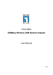
User’s Manual
Warranty
All products manufactured by ICP DAS are under warranty
regarding defective materials for a period of one year from the date
of delivery to the original purchaser.
Warning
ICP DAS assumes no liability for damages resulting from the
use of this product. ICP DAS reserves the right to change this
manual at any time without notice. The information furnished by
ICP DAS is believed to be accurate and reliable. However, no
responsibility is assumed by ICP DAS for its use, or for any
infringements of patents or other rights of third parties resulting
from its use.
Copyright
Copyright 2007 ~ 2008 by ICP DAS. All rights are reserved.
Trademark
The names used for identification only may be registered
trademarks of their respective companies.
GW-7433D MODBUS TCP/RTU to CANopen Gateway User Manual
(Version 2.0.0, Jul/2011)
1
Table of Contents
1
2
3
4
5
General Information ..................................................................................3
1.1
CANopen Introduction ................................................................3
1.2
CANopen Applications................................................................5
1.3
Module Characteristics ...............................................................6
1.4
Hardware Features.....................................................................7
1.5
Firmware Features .....................................................................7
1.6
Specifications .............................................................................8
1.7
Typical Applications ....................................................................9
1.8
Modbus TCP/RTU to CANopen gateway .................................10
Hardware ................................................................................................12
2.1
Pin Assignment.........................................................................12
2.1.1
RS-232 & RS-485 & Power supply interface .....................13
2.1.2
Connect to CANopen devices ...........................................14
2.1.3
Ethernet connection ..........................................................15
2.1.4
Terminator resistor settings ...............................................16
2.2
LED Indication ..........................................................................18
2.2.1
Power LED ........................................................................18
2.2.2
Module Status indicator LED .............................................18
MI LED...................................................................................18
CI LED ...................................................................................18
ERR LED & ERROR Message show in 7-LED ......................18
2.2.3
5-digits 7-Segment LED Displays......................................19
CANopen Interface .................................................................................22
3.1
Network Communication ..........................................................22
3.2
Slave Device Communication...................................................22
3.3
Listen Mode..............................................................................22
3.4
Interaction with Internal Memory ..............................................23
3.5
CAN Status Message ...............................................................24
Modbus TCP/RTU Interface....................................................................25
4.1
Commands ...............................................................................25
4.2
Modbus TCP/RTU Addressing..................................................26
4.2.1
I/O Data Addressing ..........................................................26
4.2.2
Special Data Addressing ...................................................26
Appendix A – Software............................................................................29
5.1
GW-7433D Utility......................................................................29
5.2
Modbus Utility ...........................................................................30
GW-7433D MODBUS TCP/RTU to CANopen Gateway User Manual
(Version 2.0.0, Jul/2011)
2
1 General Information
1.1 CANopen Introduction
The CAN (Controller Area Network) is a serial communication protocol,
which efficiently supports distributed real-time control with a very high level of
security. It is an especially suited for networking “intelligent” devices as well as
sensors and actuators within a system or sub-system. In CAN networks, there
is no addressing of subscribers or stations in the conventional sense, but
instead, prioritized messages are transmitted. CANopen is one kind of the
network protocols based on the CAN bus and mainly used for machine control
network, such as textile machinery, printing machines, injection molding
machinery, or packaging machines, etc. CANopen is a low level network that
provides connections between simple industrial devices (sensors, actuators)
and higher-level devices (controllers), as shown in Figure 1.1.
Figure 1.1 Example of the CANopen network
CANopen was developed as a standardized embedded network with
highly flexible configuration capabilities. It provides standardized
communication objects for real-time data (Process Data Objects, PDO),
GW-7433D MODBUS TCP/RTU to CANopen Gateway User Manual
(Version 2.0.0, Jul/2011)
3
configuration data (Service Data Objects, SDO), network management data
(NMT message, and Error Control), and special functions (Time Stamp, Sync
message, and Emergency message). Nowadays, CANopen is used in many
various application fields, such as medical equipment, off-road vehicles,
maritime electronics, public transportation, building automation and so on.
Baud rate (bit/s)
Max. Bus length (m)
10 K
5000m
20 K
2500 m
50 K
1000 m
125 K
500 m
250 K
250 m
500 K
100 m
800 K
50 m
1M
25 m
Table 1.1 The Baud rate and the Bus length
GW-7433D MODBUS TCP/RTU to CANopen Gateway User Manual
(Version 2.0.0, Jul/2011)
4
1.2 CANopen Applications
CANopen is the standardized network application layer optimized for
embedded networks. Its specifications cover the standardized application layer,
frameworks for the various applications (e.g. general I/O, motion control
system, maritime electronics and so forth) as well as device, interface, and
application profiles.
The main CANopen protocol and products are generally applied in the
low-volume and mid-volume embedded systems. The following examples
show some parts of the CANopen application fields. (For more information,
please refer to the web site, http://www.can-cia.org):
● Truck-based superstructure control systems
● Off-highway and off-road vehicles
● Passenger and cargo trains
● Maritime electronics
● Factory automation
● Industrial machine control
● Lifts and escalators
● Building automation
● Medical equipment and devices
● Non-industrial control
● Non-industrial equipment
GW-7433D MODBUS TCP/RTU to CANopen Gateway User Manual
(Version 2.0.0, Jul/2011)
5
1.3 Module Characteristics
“Embedded Internet” and “Embedded Ethernet” are hot topics today.
Nowadays the Ethernet protocol becomes the de facto standard for local area
network. Via Internet, connectivity is occurring everywhere, from home
appliances to vending machines to testing equipment to UPS…etc. Using
Ethernet for network in industrial area is appealing because the required
cabling is already installed.
The GW-7433D from ICP DAS is a solution that provides a
communication protocol to transfer the Modbus TCP/RTU to CANopen
protocol and solves a mission-critical problem, connecting an existing
CANopen network to Ethernet-base PLCs and PC-based configuration and
monitor system. It enables CANopen networks to be coupled together over the
Internet/Ethernet, whereby remote monitoring and control is possible.
The GW-7433D can be a CANopen master device in the CAN bus on
the CANopen network. On the Ethernet network, it acts as a Modbus TCP
server of Modbus RTU slave. Users can use Modbus TCP/RTU class 0, class
1 and partial class 2 functions to communicate with it. In addition, we also
provide Utility software for users to configure their device parameters for the
GW-7433D. The following figure shows the application architecture for the
GW-7433D.
Figure 1.2 System application
GW-7433D MODBUS TCP/RTU to CANopen Gateway User Manual
(Version 2.0.0, Jul/2011)
6
1.4 Hardware Features
●
●
●
●
●
●
●
●
●
●
●
80186, 80MHz CPU, or compatible
NXP SJA1000 CAN controller with 16 MHz clock
NXP 82C250 CAN Transceiver
1K VDC isolation on CAN side.
Support CAN specification 2.0A.
Jumper select 120Ω terminator resistor for CAN channel
10/100 BASE-T DM9000AE compatible Ethernet Controller
Support one RS-232 port, one RS-485 port and one CAN port
Built-in self-tuner ASIC controller on RS-485 port
7-segment LED display.
MI LED , CI LED , ERR LED
1.5 Firmware Features
● Allow to export/import the configuration of the GW-7433D to/from an
xml file.
● Programmable CANopen transfer rate 10 k, 20 k, 50 k, 125 k, 250 k,
500 k, 800 k, 1 Mbps.
● Support up to 10 CANopen slave devices.
● Support maximum I/O: 3072 DI channels, 3072 DO channels, 640 AI
channels, and 640 AO channels.
● Support message numbers: TxPDO+RxPDO+TxSDO+RxSDO are
more than 120.
● Allow on-line adding device into CANopen network.
● Support boot-up auto communicate with slave devices.
● Provide CAN off-line detection.
● Support Node Guarding protocol and Heartbeat Consumer protocol.
● Provide Boolean, byte, word, and double word data types.
● Mapping the CANopen object to the Modbus address to by utility tool.
● Support Modbus TCP server or Modbus RTU slave functions at the
same time.
● Allowed multi-Modbus TCP client access simultaneously.
GW-7433D MODBUS TCP/RTU to CANopen Gateway User Manual
(Version 2.0.0, Jul/2011)
7
1.6 Specifications
●
●
●
●
●
●
●
●
RS-232 specification (COM1):
○ Communication speed: 115200 bps Max.
○ RS-232: TXD, RXD, RTS, CTS, GND.
○ Non-isolation.
○ Firmware upgrades port.
RS-485 specification (COM2):
○ Communication speed: 115200 bps Max.
○ D2+, D2-.
○ Non-isolation.
○ Self-tuner ASIC inside.
Ethernet specification:
○ 10/100 Base-T.
CAN specification:
○ CAN signal support: CAN_H, CAN_L.
○ CAN bus interface: ISO 11898-2, screw terminal connector.
○ Isolation voltage: 1K VDC isolation on the CAN side.
Power requirement:
○ Unregulated +10VDC ~ +30VDC.
○ Power reverse protection, Over-Voltage brown-out protection.
○ Power consumption: 3W.
Module specification:
○ Dimensions: 123mm x 64.5mm x 19.6mm.
○ Operating temperature: -25 to 75ºC.
○ Storage temperature: -30 to 80ºC.
○ Humidity: 10 to 90%, non-condensing.
○ LEDs: Power, MI, CI, Err, and 5-digits 7 segment LED displays.
Software Utility tool:
○ Online adding/removing CANopen devices via Ethernet.
○ Get/Set Modbus TCP/RTU input/output memory address.
○ Provide CANopen I/O mapping table.
○ Support TxPDO/RxPDO/TxSDO/RxSDO setting.
Application:
○ Factory Automation.
○ Building Automation.
○ Control system.
○ Monitor system.
○ Vehicle Automation.
GW-7433D MODBUS TCP/RTU to CANopen Gateway User Manual
(Version 2.0.0, Jul/2011)
8
1.7 Typical Applications
The GW-7433D is designed as a Modbus TCP server or Modbus RTU
Slave to CANopen master Gateway. It allows you to access the CANopen
slave device by using Modbus commands. A GW-7433D is able to link up to 10
CANopen slave devices. Before using the GW-7433D, it is needed to use the
GW-7433D Utility to set the GW-7433D IP address and COM port. Typical
application architecture is shown below.
Figure 1.3: Application of GW-7433D
GW-7433D MODBUS TCP/RTU to CANopen Gateway User Manual
(Version 2.0.0, Jul/2011)
9
1.8 Modbus TCP/RTU to CANopen gateway
The GW-7433D provides centralized data storage, “Internal Memory”.
This storage is shared by the CANopen and Modbus TCP/RTU network. Data
come from one communication interface will be placed into the “Internal
Memory”, then another communication interface can get the data from the
memory area. The concept of the internal memory is shown below.
Figure 1.4: Internal Memory Table of GW-7433D
The GW-7433D acts as a Modbus TCP server or Modbus RTU slave to
CANopen master gateway. Using the module, users don’t need to take care of
the detail of the CANopen protocol. The module will implement the CANopen
protocol automatically. Therefore, it can efficiently reduce the complexity of
building a CANopen network. When users would like to use SCADA software
to control and monitor the CANopen network, the GW-7433D provides a
solution for this requirement. The GW-7433D provides two kinds of protocols.
One is the PDO protocol and another is SDO protocol. Basically, the PDO
protocol is used for real I/O data. It is more efficient than the SDO because the
PDO protocol don’t have any protocol header. The SDO protocol is always
used for configuration. In some devices, the device manufacturers provide the
SDO method to get the device status. Therefore, before using the GW-7433D,
users need to read the user manual of the CANopen slave device, and confirm
the transmission protocols of the slave data which interest users. The
communication concept between the GW-7433D and CANopen slaves are
shown in the figure 1.6.
GW-7433D MODBUS TCP/RTU to CANopen Gateway User Manual
(Version 2.0.0, Jul/2011)
10
Figure1.6 CANopen Messaging
Before using the GW-7433D, users need to configure it by using
GW-7433D Utility tool. The figure 1.7 demonstrates how to let the GW-7433D
work and how to apply it in users’ CANopen network.
Figure 1.7 Four steps to establish connection
1. Connect to GW-7433D:
You have to use the GW-7433D Utility to connect to the GW-7433D first.
In this step, the IP and mask of the GW-7433D must be used.
2. Add CANopen slave devices to GW-7433D EEPROM:
You can use the GW-7433D Utility to set the I/O configuration and
communication parameters of the CANopen slave device, and save them
into the GW-7433D. In this step, users need to read the CANopen slave
user manual first, then decide what Cob-IDs are used and what CANopen
protocols are implemented.
3. Establish connection:
After finishing the configuration and close the Utility, the GW-7433D will
reboot and apply the new configuration automatically. Then, it starts to
communication with the CANopen slave devices.
4. Access I/O data:
After communicating with slave devices, users can access the I/O data
with corresponding Modbus address via the Ethernet port or COM port.
GW-7433D MODBUS TCP/RTU to CANopen Gateway User Manual
(Version 2.0.0, Jul/2011)
11
2 Hardware
2.1 Pin Assignment
Figure 2.1 Pin assignments on the GW-7433D
GW-7433D MODBUS TCP/RTU to CANopen Gateway User Manual
(Version 2.0.0, Jul/2011)
12
2.1.1 RS-232 & RS-485 & Power supply interface
The GW-7433D provides one RS-232 interface and one RS-485
interface. The GND-signal of COM1 is shared with pin-9, GND. The pin
assignment is shown in table 2-1.
Figure 2.2 Pin assignments (power side)
Pin
Name
Description
1
CTS1
CTS of COM1 (RS-232)
2
RTS1
RTS of COM1 (RS-232)
3
RXD1
RXD of COM1 (RS-232)
4
TXD1
TXD of COM1 (RS-232)
5
INIT*
Pin for enable/disable auto execution
firmware
6
D2+
Data+ of COM2 (RS-485)
7
D2-
Data- of COM2 (RS-485)
8
Vs+
V+ of power supply (+10V to +30VDC
unregulated)
9
GND
Ground of power supply
Table 2-1: COM Connector Pin Assignment
GW-7433D MODBUS TCP/RTU to CANopen Gateway User Manual
(Version 2.0.0, Jul/2011)
13
2.1.2 Connect to CANopen devices
In order to provide an easy CAN bus wiring, the GW-7433D supplies
one CAN port with two CAN bus connector interfaces. Each connecter built on
the GW-7433D looks like as figure 2.3 and table 2-2.
Pin No.
Signal
Description
1
N/A
Unavailable
2
CAN_L
CAN_L bus line (dominant low)
3
N/A
Unavailable
4
CAN_H
CAN_H bus line (dominant high)
5
N/A
Unavailable
Table 2-2 CAN bus Connector Pin Assignment
Note that the bypass CAN bus connector is not another CAN channel. It
is designed for connecting to another CAN device conveniently. The structure
of the inside electronic circuit is displayed as figure 2.4.
Figure2.4 Electronic circuit of CAN bus connector
GW-7433D MODBUS TCP/RTU to CANopen Gateway User Manual
(Version 2.0.0, Jul/2011)
14
2.1.3 Ethernet connection
The Ethernet (10/100 Base-T) signals are routed to an RJ45 socket for
easy connection using a standard CAT 3 or CAT 5 network cable. On power on
of the GW-7433D, it will auto-negotiate the network speed and connection.
Pin
Name
Description
1
TX+
Transmit Data +
2
TX-
Transmit Data -
3
RX+
Receive Data +
4
N.C.
Not Connected
5
N.C.
Not Connected
6
RX-
Receive Data -
7
N.C.
Not Connected
8
N.C.
Not Connected
Table 2-3: Ethernet Connector Pin Assignment
GW-7433D MODBUS TCP/RTU to CANopen Gateway User Manual
(Version 2.0.0, Jul/2011)
15
2.1.4 Terminator resistor settings
In order to minimize reflection effects on the CAN bus line, the CAN bus
lines have to be terminated at both ends by two terminal resistances. Based on
the ISO 11898-2 spec, each terminal resistance is 120Ω (or between
108Ω~132Ω). The length related resistance should have 70 mΩ/m. Users
should check the resistances of their CAN bus, before they install a new CAN
network as figure 2.5.
Figure 2.5 Terminator resistor
Moreover, to minimize the voltage drop on long distance, the terminal
resistance should be higher than the value defined in the ISO 11898-2. Table
2-4 may be used as a reference.
Bus Length
(meter)
Length Related
Resistance (mΩ/m)
Cross Section
(Type)
0~40
70
0.25(23AWG)~
0.34mm2(22AWG)
124 (0.1%)
40~300
< 60
0.34(22AWG)~
0.6mm2(20AWG)
127 (0.1%)
300~600
< 40
0.5~0.6mm2
(20AWG)
150~300
600~1K
< 20
0.75~0.8mm2
(18AWG)
150~300
Terminal
Resistance (Ω)
Table 2-4: Relation between bus cable and length
GW-7433D MODBUS TCP/RTU to CANopen Gateway User Manual
(Version 2.0.0, Jul/2011)
16
Therefore, the GW-7433D module supplies a jumper for users to
connect the terminator resistor or not. If users want to use this terminator
resistor, please open the GW-7433D cover and use the JP3 jumper to activate
the 120Ω terminator resistor built in the system, as in the figure 2.6. Note that
the default setting is active. And about the J3 jumper setting, please refer the
table 2-5.
Figure 2.6
XC100 I/O expansion board LAYOUT
Apply the termination resistor(120Ω)
Don’t apply the termination resistor
Table 2-5 J3 Jumper Selection
GW-7433D MODBUS TCP/RTU to CANopen Gateway User Manual
(Version 2.0.0, Jul/2011)
17
2.2 LED Indication
The GW-7433D provides three LEDs to indicate what situation is in the
GW-7433D. They are described as follows.
2.2.1 Power LED
The GW-7433D needs +10 ~ +30 VDC power input and consumes 3W.
The Power LED will be turn on after applying power and it will be flashing one
time per second.
2.2.2 Module Status indicator LED
The GW-7433D includes three single-color LED displays to indicate the
status of module, network and I/O device. They are MI LED (it is red), CI LED
(it is green), and ERR LED (it is red). The indicators assist maintenance
personnel in quickly identifying a problem unit. When the GW-7433D events
occur, these indicators will be triggered to glitter with different conditions.
MI LED
The LED indicates the Modbus communication status of the GW-7433D.
Following shows the condition of MI status. When GW-7433D is working and
has received a Modbus message, the MI LED will be flash red.
○ LED off: The GW-7433D receives no Modbus command.
○ LED on: The GW-7433D is receiving a Modbus command.
CI LED
This LED indicates the CANopen communication status of the module.
Following shows the conditions of CI status. When module is online and start
to communicate with the devices, it will flash. If there are no TxPDO, RxPDO,
TxSDO, RxSDO protocol running, then the CI LED will be turn off.
○ LED off: The GW-7433D receives no CANopen message.
○ LED on: The GW-7433D is receiving a CANopen message.
ERR LED & ERROR Message show in 7-LED
This LED indicates the CANopen status of the GW-7433D. The
following description shows the conditions of error status.
○ LED off: The GW-7433D has no error.
○ LED flash: The GW-7433D gets some communication errors.
○ LED on: GW-7433D gets some configuration errors.
Note: The table 2-6, section 3.4, and 4.2.2 have more information about
the details of error messages.
GW-7433D MODBUS TCP/RTU to CANopen Gateway User Manual
(Version 2.0.0, Jul/2011)
18
2.2.3 5-digits 7-segment LED Displays
While the GW-7433D boots up, the 5-digits 7-segment LED of the
GW-7433D shows the communication configurations and error status. All of
the information is divided into 4 groups. These groups are displayed by turns.
The information is shown as the figure 2.7.
Figure 2.7 The meaning of the 7-segment LED
The information groups of the GW-7433D are as the following list.
● Group-ID 11111: IP information of this GW-7433D
● Group-ID 22222: baud rate of all ports
● Group-ID 33333: configuration of GW-7433D station number.
● Group-ID 44444: client connection information and error state of this
GW-7433D
The IP information format of the GW-7433D is given as follows:
● Group-ID of 5-digit LED: 11111.
● LED-1: indicator, can be 1 or 2 or 3 or 4 for 4 sections of IP address
● LED-2~5: IP address
GW-7433D MODBUS TCP/RTU to CANopen Gateway User Manual
(Version 2.0.0, Jul/2011)
19
The LED shows Group-ID first, and then shows its IP address as the
figure 2.7. If users change the IP address, the value shown on the LED will be
changed immediately. The default IP address is 192.168.255.1 and the default
Mask is 255.255.0.0.
The baud rate of the COM1, COM2 and CAN port are given as follows:
● Group-ID of 5-digit LED: 22222.
● LED-1: port number. 1 for COM1, 2 for COM2, 3 for CAN port.
● LED-2~5: baud rate. This value needs to multiply by 1000. For COM1
and COM2, the range is from 1.2~115.2 (means 1.2 kbps ~ 115.2 kbps).
For CAN port, the range is from 10~1000 (means 10 kbps ~ 1000 kbps)
The configuration of the communication is given as follows:
● Group-ID of 5-digit LED: 33333.
● LED-1: indicators, always 1.
● LED-2, 3: fix string, “id.”.
● LED-4, 5: The Modbus station ID of the GW-7433D.
The connection-client information is given as follows:
● Group-ID of 5-digit LED: 44444.
● LED-1: indicators, always 1.
● LED-2, 3: total supported socket numbers (5 sockets).
● LED-4, 5: numbers of sockets are used by clients, default 0.
If any client connects to the GW-7433D, the numbers of the
used-socket will be increased. The GW-7433D allows 5 clients for connection.
So if the used-socket number is 5, no more clients can link to the GW-7433D.
The error status of the GW-7433D is given as follows:
● LED-1~3: fix string, “-Er”.
● LED-4, 5: error code, normal is 00. The details of the error codes are
shown below (table 2-6).
Users also can get the error status by the Modbus commands. For the
details please refer to the section 3.4 and 4.2.2.
GW-7433D MODBUS TCP/RTU to CANopen Gateway User Manual
(Version 2.0.0, Jul/2011)
20
Error code (LED)
Description
-Er00
No error
-Er45 *
Guarding or Heartbeat event occurred
-Er46 *
Guarding or Heartbeat setting error
-Er47 *
A CANopen slave had disconnected
-Er48 *
Transmit / receive CAN data error
-Er49 *
CAN Bus off
-Er50 *
EEPROM initialization error
-Er51
CANopen slave amount over the range (1 ~ 10)
-Er52
CANopen slave node ID is over the range (1 ~ 127)
-Er53
There is a PDO COB_ID over the range (0 ~ 0x7FF)
-Er54 *
Install com port error
-Er55 **
PDO Count >100
-Er56 **
SDO Count >15
-Er57 *
Total DO channels are over 3072 (384 bytes)
-Er58 *
Total DI channels are over 3072 (384 bytes)
-Er59 *
Total AO channels are over 640
-Er60 *
Total AI channels are over 640
Table 2-6 Error code table
** : Only for the GW-7433D firmware v2.00 or later.
** : Only for the GW-7433D firmware v1.xx.
GW-7433D MODBUS TCP/RTU to CANopen Gateway User Manual
(Version 2.0.0, Jul/2011)
21
3 CANopen Interface
3.1 Network Communication
The GW-7433D, Modbus TCP/RTU to CANopen Gateway, acts as a
CANopen master on CANopen network. It can exchange I/O data with up to 10
modules. Users can use the GW-7433D Utility tool to mapping CANopen
slave’s data into the GW-7433D via Ethernet, and then the GW-7433D will
work.
3.2 Slave Device Communication
After the configuration of CANopen slave devices, please run the
CANopen slave device in the pre-operation mode. Use the GW-7433D utility to
configure the mapping table of the CANopen slave’s data. When you finish the
GW-7433D utility configuration and close the utiltiy, the GW-7433D will auto
re-boot the firmware, and poll the TxPDO and TxSDO data of the CANopen
slave devices as soon as possible. The RxPDO and RxSDO communication
are decided by the mode. If the cyclic mode is used, the GW-7433D sends the
RxPDO cyclically even the DO or AO data are the same as previous ones. If
users use normal mode, the RxPDO is only sent while the GW-7433D gets the
Modbus command to send the DO or AO data.
3.3 Listen Mode
If users want the GW-7433D to monitor the CANopen network but not to
send any message to the CANopen network, this function will be useful. For
example, if users have two GW-7433Ds in his application, the one is in normal
mode and another is in listening mode, the input data (DI / AI) of the one in the
listen mode will be the same as the one in normal mode. Therefore, users can
use this function to be the second monitor of the CANopen network.
GW-7433D MODBUS TCP/RTU to CANopen Gateway User Manual
(Version 2.0.0, Jul/2011)
22
3.4 Interaction with Internal Memory
When the GW-7433D works, it monitors the CANopen network and
updates the AI or DI data in the corresponding internal memory if these data
responds from the CANopen slaves automatically. The GW-7433D also uses
RTR message to get the DI and AI data, and put these data into the
corresponding internal memory. When the Modbus TCP client or Modbus RTU
master commands to the GW-7433D for getting AI or DI data, the GW-7433D
reply the AI and DI data from the internal memory. When the Modbus TCP
client or Modbus RTU master wants to output the data to the DO or AO
channels of the CANopen slaves, it send Modbus commands to the
GW-7433D. Then, GW-7433D keeps theses data in the corresponding internal
memory and sends the CANopen messages immediately or cyclically (due to
the RxPDO mode) for outputting the DO and AO data. When users use the
cyclic mode of the RXPDO, the GW-7433D will update the DO or AO data by
using the data in the corresponding internal memory cyclically.
Figure 3.1 Internal Memory Table of GW-7433D
GW-7433D MODBUS TCP/RTU to CANopen Gateway User Manual
(Version 2.0.0, Jul/2011)
23
3.5 SJA1000 CAN Status
Users can use the Modbus command to get the CAN status of the
SJA1000 CAN controller which is applied in GW-7433D. The meaning of each
bit of the CAN status is as follow table 3-1. About how to get the CAN status
please refer to the section 4.2.2 (Special Data Addressing).
Bit
Name
Value
Bus Status
1
Bit. 7
0
Error Status
1
Bit. 6
Bit. 5
Bit. 4
Transmit Status
Receive Status
Transmission
Bit. 3
Complete Status
Bit. 2
Status
Bit. 1
Status
bus-on; the SJA1000 is ready to access the CANopen network.
error; at least one of the error counters has reached or exceeded
the CPU warning limit
1
transmit; the SJA1000 is transmitting a message
0
idle; no transmit message is in progress
1
receive; the SJA1000 is receiving a message
0
idle; no receive message is in progress
1
1
1
0
Bit. 0
network
ok; both error counters are under the warning limit
0
Data Overrun
bus-off; the SJA1000 is not allowed to access the CANopen
0
0
Transmit Buffer
Function
complete; the last requested transmission has been successfully
completed
incomplete; the previously requested transmission is not yet
completed
released; the CPU may write a message into the transmit buffer
locked; the CPU cannot access the transmit buffer; a message is
waiting for transmission or is already in process
overrun; a message was lost because there was not enough
space for that message in the RXFIFO
absent; no data overrun has occurred since the last clear data
overrun command was given
Receive Buffer
1
full; one or more messages are available in the RXFIFO
Status
0
empty; no message is available
Table 3-1 Bit interpretation of the CAN status
GW-7433D MODBUS TCP/RTU to CANopen Gateway User Manual
(Version 2.0.0, Jul/2011)
24
4 Modbus TCP/RTU Interface
The GW-7433D supports class 0, class 1 and partial class 2 Modbus slave
functionalities. The Modbus TCP client or Modbus RTU master connected to
the GW-7433D needs to follow the Modbus TCP/RTU specification 1.0.
The GW-7433D can handle maximum 5 Modbus TCP connections, and one
RS-232(COM1) or RS-485(COM2) connection simultaneously.
4.1 Commands
The following Modbus TCP/RTU commands are supported by the GW-7433D.
Function
Function Name
Class
Affects
Data Type
1
Read Multiple Coils
1
DO
Bit
2
Read Multiple Input Discrete
1
DI
Bit
3
Read Multiple Registers
0
AO
Word
4
Read Multiple Input Registers
1
AI
Word
5
Write Single Coil
1
DO
Bit
6
Write Single Register
1
AO
Word
15
Force Multiple Coils
2
DO
Bit
16
Force Multiple Registers
0
AO
Word
Table 4-1: Modbus Commands
GW-7433D MODBUS TCP/RTU to CANopen Gateway User Manual
(Version 2.0.0, Jul/2011)
25
4.2 Modbus TCP/RTU Addressing
4.2.1 I/O Data Addressing
The GW-7433D provides a piece of the internal memory for saving I/O
data. The table 4-2 shows the detail information of the memory type, data type,
address, and so on. After using GW-7433D Utility to configure the mapping
information of the CANopen slaves, users can get the mapping table between
the Modbus address and CANopen data. The information of the Modbus
memory assignment and corresponding data type are shown below.
Memory Command
Type
Start Addr
PLC
Start Addr
Max
channel
Support CANopen
Data Type
Support
Function
DI
0000h
00001h
3072
Boolean
2
DO
0000h
10001h
3072
Boolean
1, 5, 15
AI
0000h
30001h
640
Byte, Word, 4-byte
4
AO
0000h
40001h
640
Byte, Word, 4-byte
3, 6, 16
Table 4-2: I/O Data Addressing
4.2.2 Special Data Addressing
The GW-7433D supports special data such as the error status of the
CANopen slave, reset command, and so on. The table 4-3 shows the details of
these special data addresses.
Type
AI
AI
AI
Address
Description
Max. AI address + n
Read nth CANopen slave’s error status.
*1 *2
*4
Max. AI address + N + 1
Read the GW-7433D’s error status.
*3
*4
Max. AI address + N + 2
Read the GW-7433D’s CAN status.
*3
*5
GW-7433D MODBUS TCP/RTU to CANopen Gateway User Manual
(Version 2.0.0, Jul/2011)
26
AO
AO
Max. AO address + n
Reset nth CANopen slave. (write only)
*1 *2
*6
Max. AO address + N + 1 Reset the GW-7433D. (write only)
*3
AO
*7
Max. AO address + N + 2 Set the GW-7433D to “Listen Mode”
*3
*8
Table 4-3: Special Data Addressing
*1: The Max. AI/AO address is decided by the maximum AI/AO channels
configuration by utility. For example, if users finish the configuration by the
GW-7433D utility, check the mapping table and find that there are 8 AI data
(16-bytes) assigned in the Modbus memory, the Max. AI address is 0007h (or
30008h for PLC) because the useful AI channel is from 0 ~ 7.
*2: “n” is the CANopen slave device number. The number range is 1 ~ 10.
*3: “N” is the total CANopen slave device amount.
*4: About the error status, please refer to the table 2-6.
*5: About the CAN status, please refer to the table 3-1.
*6: Writing the address (Max. AO address + n) to 1 will let the GW7433D send
a CANopen reset command to nth CANopen slave.
*7: Writing the address (Max. AO address + N + 1) to 1 will let the GW-7433D
reboot.
*8: Writing the address (Max. AO address + N + 2) to 1 will let the GW-7433D
into listen mode. If users want to recover to the normal mode, please write it to
0. About the details of “Listen Mode”, please refer to section 3.3.
GW-7433D MODBUS TCP/RTU to CANopen Gateway User Manual
(Version 2.0.0, Jul/2011)
27
Example 1: Get the CANopen slave device’s error status.
Assume that the GW-7433D connects 2 CANopen slaves and with total 10
AI channels, users can send the follow Modbus TCP command to get these
two CANopen slaves’ status.
Query
--> 1 2 0 0 0 6 01 04 00 0A 00 02
Response --> 1 2 0 0 0 6 01 04 04 00 00 00 2F (for Big-endian data type*)
The green word 00 0A is the address for the CAN error status because
the address 00 00 ~ 00 09 are for AI data. The orange word 00 02 indicates
getting the error status of two slaves. The blue word is 1st CANopen slave’s
error status, and 00 00 means no error. The red data is 2nd CANopen slave’s
error status, and 00 2F (47) means the slave has disconnected.
Example 2: Reset the CANopen slave device.
Assume the GW-7433D connects 2 CANopen slaves and with total 8
AO channels. When users want to reset 2nd CANopen slave, users can send
the follow Modbus TCP command to the GW-7433D and it will send a
CANopen reset command to the slave.
Query
--> 1 2 0 0 0 6
Response --> 1 2 0 0 0 6
01 06 00 09 00 01 (for Big-endian data type*)
01 06 00 09 00 01 (for Big-endian data type*)
The address 00 09 is the 2nd CANopen slave reset command address
because the 00 08 is 1st CANopen slave reset command address and the 00
00 ~ 00 07 are the address for AO channel 0 ~ 7. The command 00 01 is to
reset 2nd CANopen slave.
* GW-7433D Modbus data support two kinds of the word data type,
Little-endian and Big-endian, and the Big-endian type is the default type.
The different type will influence the data byte order. Users can select this
type through GW-7433D Utility.
GW-7433D MODBUS TCP/RTU to CANopen Gateway User Manual
(Version 2.0.0, Jul/2011)
28
5 Appendix A – Software
5.1 GW-7433D Utility
The GW-7433D utility is a setting tool for the GW-7433D configuration.
The details about the GW-7433D utility please refer to the GW-7433D
utility user manual. Users can get the utility tool from the following
positions.
Path in product CD:
CD://Fieldbus_cd/canopen/gateway/gw-7433d/utility/
Download website:
http://ftp.icpdas.com/pub/cd/fieldbus_cd/canopen/gateway/gw-7433d/utility/
Get the utility manual for the following positions:
Path in product CD:
CD://Fieldbus_cd/canopen/gateway/gw-7433d/manual/
Download website:
http://ftp.icpdas.com/pub/cd/fieldbus_cd/canopen/gateway/gw-7433d/manual/
GW-7433D MODBUS TCP/RTU to CANopen Gateway User Manual
(Version 2.0.0, Jul/2011)
29
5.2 Modbus Utility
The Modbus utility includes the MBTCP and MBRTU tools. The
MBTCP is a Modbus TCP clientl with source code in VB6. The MBRTU is
a Modbus RTU master with source code in VB6. These two tools are
designed by ICP DAS and they are helpful when users want to diagnostic
the Modbus TCP server devices or Modbus RTU slaves. Users can free
download the utilty from the following web site:
http://www.icpdas.com/products/PAC/i-8000/modbus_web_download.htm
GW-7433D MODBUS TCP/RTU to CANopen Gateway User Manual
(Version 2.0.0, Jul/2011)
30