1
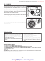
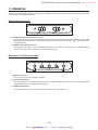
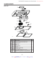
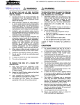
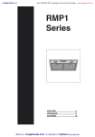
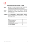
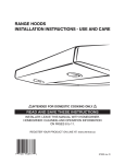
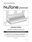
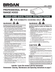
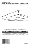
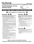
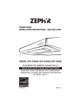
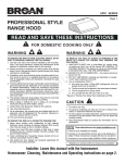
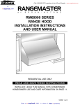
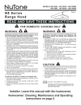
Call 1-800-667-8721 anywhere in the US and Canada - www.rangehoods.com
5. INSTALL THE ADAPTER/DAMPER (CONT’D)
VERTICAL
DISCHARGE
For a vertical discharge installation only, leave the foldable flange (C) of the
adapter/damper as is. This flange must be located towards the front of the hood.
See beside.
C
HO0057
ALL
INSTALLATIONS
Using two 1/2” screws, secure the adapter/damper to the top or back of the
hood. Tape the adapter/damper to the hood using duct tape to seal it.
HO0058
NOTES: 1. For the best ventilation performance, if a round duct must be used, the duct diameter must be 6” or more. Use a
3¼” x 10” to 6” round transition.
2. The wall duct must be well prepared to receive the adapter. Before performing the installation, make sure the
adapter fits easily in the duct.
6. INSTALL THE HOOD
Run power cable to installation location. Place the hood at its location.
Using a pen, mark the position of the screws (smaller part of the
embossed keyholes). Remove the hood and install four 1/2” double thread
screws at sides locations (A), leaving a 1/8” gap. Place the wire clamp,
insert the cable in the hood and tighten the wire clamp to secure the cable.
Place the hood under the cabinet and slide it in position. Make sure the
adapter/damper assembly enters the ducting and the damper opens freely.
Secure the hood by tightening the screws completely. Install the last 1/2”
double thread screw (B) in the remaining embossed hole.
B
A
A
HD0217
7. CONNECT WIRING
! WARNING
Risk of electrical shock. Electrical wiring must be done by qualified personnel in accordance with all applicable codes
and standards. Before connecting wires, switch power off at service panel and lock service disconnecting means to
prevent power to be switched on accidentally.
Connect cable to range hood wiring using included wire connectors.
Connect BLACK to BLACK, WHITE to WHITE and GREEN or BARE WIRE
to GREEN ground screw (1).
1
! WARNING
Do not forget to connect the ground!
HE0059
-7Broan at :: rangehoods . com
is a division of
kitchen :: accessories
U
N
L
I
M
I
T
E
D
Call 1-800-667-8721 anywhere in the US and Canada - www.rangehoods.com
8. REINSTALL BOTTOM PANEL AND FILTERS
Reinstall the bottom panel, using the retaining screw previously removed in
step 4 plus 4 others from parts bag. Refer to illustration beside.
Then, reinstall filters.
HO0092
9. FLUORESCENT LAMPS
! WARNING
This hood has fluorescent lamps containing mercury. Dispose of appropriately, according to local laws and requirements.
This range hood must use compact fluorescent lamps (120 V, 13 W, PLC13, 2700 K with G24q-1 base) (included).
NOTE: The range hood is shipped with both fluorescent lamps packed behind the light diffuser.
1. To access fluorescent lamps, remove the light diffuser by pushing on its both tabs and pulling it down.
2. To install the fluorescent lamps, slide their 4 prongs into their corresponding holes in their socket until secured. Reinstall the
light diffuser.
2
1
HO0099
! WARNING
In order to prevent the risk of personal injury, the fluorescent lamps must be cooled down before removing them.
To remove fluorescent lamps, remove the light diffuser and pull fluorescent lamps out of their socket.
NOTE: Some fluorescent lamps may produce a yellowish lighting on first usages. This temporary effect will disappear out in
time by itself.
-8Broan at :: rangehoods . com
is a division of
kitchen :: accessories
U
N
L
I
M
I
T
E
D
Call 1-800-667-8721 anywhere in the US and Canada - www.rangehoods.com
10. CLEANING
The grease filters, bottom panel, intake ring (A) and blower wheel (B) should
be cleaned frequently. Use a warm detergent solution. The grease filters,
intake ring and blower wheel are dishwasher safe.
Clean all-metal filters in the diswasher using a non-phophate detergent.
Discoloration of the filter may occur if using phosphate detergents, or as a
result of local water conditions — but this will not affect filter performance.
This discoloration is not covered by the warranty.
C
To remove the blower wheel, first take off its intake ring. Then remove the
blower wheel by pulling it down smoothly.
NOTE: Do not try to remove the black part (C) attached to the bottom panel.
B
A
HD0221
D
When reinstalling the blower wheel, make sure the small tab (D) will fit into
one hole of the motor.
HD0156
STAINLESS
STEEL CLEANING:
Do:
• Regularly wash surfaces with clean cloth or rag soaked
with warm water and mild soap or liquid dish detergent.
• Always clean in the direction of original polish lines.
• Always rinse well with clear water (2 or 3 times) after
cleaning. Wipe completely dry.
• You may also use a specialized household stainless steel
cleaner.
Don’t:
• Do not use any steel or stainless steel wool or any other
scrapers to remove stubborn dirt.
• Do not use any harsh or abrasive cleansers.
• Do not allow dirt to accumulate.
• Do not let plaster dust or any other construction residues
reach the hood. During construction or renovation, cover
the hood to make sure no dust adheres to stainless steel
surface.
Avoid: when choosing a detergent
- Any cleaners that contain bleach will attack stainless steel.
- Any products containing: chloride, fluoride, iodide, bromide will deteriorate surfaces rapidly.
- Any combustible products used for cleaning such as acetone, alcohol, ether, benzol, etc., are highly explosive and should
never be used close to a range.
ENAMEL FINISH:
Clean with warm water and mild detergent only. If discoloration occurs, use a good enamel polish such as automotive polish.
(DO NOT use rough abrasive cleaner or porcelain cleaner.)
-9Broan at :: rangehoods . com
is a division of
kitchen :: accessories
U
N
L
I
M
I
T
E
D
Call 1-800-667-8721 anywhere in the US and Canada - www.rangehoods.com
11. OPERATION
Always turn on the hood before begining cooking in order to establish an air flow in the kitchen. Let the blower run for a few minutes
to clear the air after turning off the range.
ROCKER SWITCH CONTROL
A
HC0031
B
A. ON/OFF BLOWER AND SPEED CONTROL SWITCH:
This 3-position rocker switch controls the blower speed. Pressing on left side (1) will result in low speed operation, while
pressing on right side (2) will turn on the blower to high speed. To stop the blower operation, set the rocker switch to the
central position (0).
B. ON/OFF LIGHTING CONTROL SWITCH:
This 3-position rocker switch controls the lighting. Press either on left side (1) or right side (1) to obtain full lighting.
To shut off the lights, set the rocker switch to the central position (0).
MECHANICAL PUSH-BUTTON CONTROL
HC0021
A
B
C
A. OFF BLOWER SWITCH:
Press on this switch to stop the blower operation.
B. SPEED BLOWER SWITCHES:
Press on left switch (1) to turn on the blower on low speed, on middle switch (2) to turn on the blower on medium speed, and
on right switch (3) to turn on the blower on high speed.
C ON/OFF LIGHTING SWITCH :
Press on this switch to turn on the fluorescent lights, and press again to turn them off.
- 10 Broan at :: rangehoods . com
is a division of
kitchen :: accessories
U
N
L
I
M
I
T
E
D
Call 1-800-667-8721 anywhere in the US and Canada - www.rangehoods.com
12. SERVICE PARTS
MODEL QDE
1
2
3
4
12
5
11
6
10
7
9
8
HL0095
KEY PART
No.
No.
1
V13296
V15434
2
V15433
3
V03623
4
V01752
5
V01765
6
V01988
V16119
7
V16117
8
V01757
9
V14131
10 V02104
11 V06756
12 V03649
*
V06727
*
V04281
DESCRIPTION
QTY
1
ADAPTER/DAMPER
1
ROCKER SWITCH WHITE (PAIR)+ OVERLAY WHITE
ROCKER SWITCH BLACK (PAIR)+ OVERLAY BLACK
1
FLUORESCENT LAMP
2
LIGHT DIFFUSER
1
MOTOR
1
BLOWER WHEEL
1
1
BOTTOM PAN WHITE
1
BOTTOM PAN BLACK
INLET RING
1
1
MICROMESH FILTER (THE PAIR)
SECONDARY CAPACITOR 7.5µF
1
1
CAPACITOR 11.5µF
BALLAST HARNESS (SOCKET LAMPS INCLUDED)
1
INSTALLATION & USER MANUAL
1
HARDWARE BAG: (1) WIRE CLAMP, (2) WIRE CONNECTORS
1
(6) NO. 6 X 1/2” SCREWS, (5) NO. 8 X 1/2” DOUBLE THREAD SCREWS
* Item not shown
- 12 Broan at :: rangehoods . com
is a division of
kitchen :: accessories
U
N
L
I
M
I
T
E
D