1
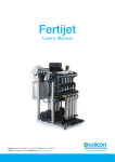
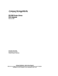
Instrucon Manual
DPD Dual Series Digital Pyrometer Gauge
DPD Series CHT/EGT Pyrometer
Part Number
CHT Scale
EGT Scale
DPD-CHT/EGT-C
0 to 400 °C
350 to 900 °C
DPD-CHT/EGT-F
100 to 700 °F
700 to 1800 °F
DPD Series EGT/EGT Pyrometer
Part Number
05-2013
EGT Scale
DPD-EGT/EGT-0700-C
150 to 700 °C
DPD-EGT/EGT-0900-C
350 to 900 °C
DPD-EGT/EGT-1200-F
200 to 1200 °F
DPD-EGT/EGT-1800-F
700 to 1800 °F
www.TheSensorConnecon.com
Page 1 of 10
Instrucon Manual - DPD Series Pyrometer
Wiring Harness:
Pin Number
Color
Funcon
1
Brown
Probe 1 Analog Output +
Note: For use with data logger
2
Probe 2 Analog Output +
Red
Note: For use with data logger
3
Brown / White
Probe 1 High Temperature Alarm Output
4
Pink
Nigh9me Mode Display Dim Input *
Note: Hi/LO Funcon acvated with input voltage > 5 V
5
Black
Variable Display Dimming Input **
6
Red / White
Probe 2 High Temperature Alarm Output
7
Orange
System Power Input ***
Note: +10 to +26 VDC
8
System Power Ground (Connect to Vehicle Chassis)
Green
* Typically connected to parking light (front sidelights) switch
** This wire is normally connected to the dimmer resistor where the resistor is fi@ed in the negave end of the dash
lights. If dash light dimming is performed by varying the posive voltage of the dash lights, then leave this wire disconnected
*** CAUTION: As a safety precauon, the +12V terminal of this product should be fused before connecng to the
12V ignion switch. We recommend using a 1 Amp, 3AG fast-acng type cartridge fuse (Li@lefuse® # 312 001 or an
equivalent).
①
⑧
Connector (Front View)
05-2013
www.TheSensorConnecon.com
Page 2 of 10
Instrucon Manual - DPD Series Pyrometer
Connecng to the Amplifier:
Channel 2:
Channel 1:
EGT Probe
EGT Probe /
CHT Sensor
Connect to
Pyrometer
cable
Wiring the Probe Connector:
Use a Type K Thermocouple Mini Connector (with flat pins)
The Sensor Connecon p/n: CON-MP-MINI-K
Type K Thermocouple Internaonal Color Codes:
Country Made:
USA & Canada* Japan
Germany
Brish
France
(+) Posive Wire
YELLOW
RED
RED
BROWN
YELLOW
(-) Negave Wire
RED
WHITE
GREEN
BLUE
PURPLE
* Note: All EGT and CHT sensors from The Sensor Connecon follow USA color codes
05-2013
www.TheSensorConnecon.com
Page 3 of 10
Instrucon Manual - DPD Series Pyrometer
Connecng to the Gauge:
The back of the gauge is fi@ed with 2 connectors; a 6 pin connector and a 7 pin connector. Plug the cable from the amplifier in to the 7 pin connector only. The 6 pin connector is not used.
Push Bu@on Funcons:
Display Stored Peak Hold Readings
During normal operaon, a momentary press of the push bu@on will recall the
stored peak temperature values. When in peak recall mode, the le@ers “PH” are
displayed in the lower poron of the pyrometer dial face. The peak values will
stay on the display for about 3 seconds before the display will return to showing
the actual temperature values.
Reset Stored Peak Hold Readings
During normal operaon, pressing and holding the push bu@on for 3 seconds will
reset the stored peak values
Enter Programming Mode
To enter Programming mode, press and hold the push bu@on with ignion and
park lights off. Then keep the push bu@on pressed down while turning the
ignion on. The pyrometer will power up in Programming mode.
05-2013
www.TheSensorConnecon.com
Page 4 of 10
Instrucon Manual - DPD Series Pyrometer
Programming Funcons:
To enter Programming mode, press and hold the push bu@on with ignion and park lights off. Then keep the push bu@on
pressed down while turning the ignion on. The pyrometer will power up in Programming mode.
Display Value
1
Funcon
Instrucons
Change Display Backlight Color
Pressing and holding the push bu@on will cause the gauge
to cycle through all of the backlight color opons. Simply
keep the bu@on depressed unl the desired color is on the
display and then let go of the bu@on. The gauge will then
step to the next Programming funcon.
Opons: 11 user selectable colors
2
Change Display High Temperature Warning Color
Opons: RED or AMBER
Pressing and holding the push bu@on will cause the gauge
to cycle through both of the 2 warning background color
opons. Simply keep the bu@on depressed unl the desired
color is on the display and then let go of the bu@on. The
gauge will then step to the next Programming funcon.
3
Change Probe 1 Alarm Set-point
Pressing and holding the push bu@on will cause the gauge
to step through all of the Probe 1 Alarm points. Simply keep
the bu@on depressed unl the desired Alarm point is
reached on the display and then let go of the bu@on. The
gauge will then step to the next Programming funcon.
4
Change Probe 2 Alarm Set-point
Pressing and holding the push bu@on will cause the gauge
to step through all of the Probe 2 Alarm points. Simply keep
the bu@on depressed unl the desired Alarm point is
reached on the display and then let go of the bu@on. The
gauge will then step to the next Programming funcon.
Increase Display Nigh2me Brightness Level
Pressing and holding the push bu@on will cause the gauge
to increase the Nigh9me brightness se9ng. Simply keep
the bu@on depressed unl the desired brightness is reached
on the display and then let go of the bu@on. The gauge will
then step to the next Programming funcon.
+ILL
Note: Make sure you turn on the parking lights
when making adjustments otherwise you will not
be able to see the effect of the adjustment
-ILL
Decrease Display Nigh2me Brightness Level
Note: Make sure you turn on the parking lights
when making adjustments otherwise you will not
be able to see the effect of the adjustment
Pressing and holding the push bu@on will cause the gauge
to decrease the Nigh9me brightness se9ng. Simply keep
the bu@on depressed unl the desired brightness is reached
on the display and then let go of the bu@on. The gauge will
then step to the next Programming funcon.
To exit Programming mode, turn off ignion and parking lights off. When you turn the ignion back on, the pyrometer will power up in Normal Operaon mode with all of the se9ngs saved.
05-2013
www.TheSensorConnecon.com
Page 5 of 10
Instrucon Manual - DPD Series Pyrometer
Error Codes:
The DigiLite DPD Series gauge has an intelligent warning system that annunciates a Warning Code in the bo@om poron of the
gauge display. The Error Code is symbolized by the le@er “E”, followed by a number.
Display Value
Error
Comment
E0
Loss of Communicaon with Amplifier Module
This can be caused by a break or short in the Yellow wire
coming from the Amplifier module, or possibly a failure in
the Pyrometer gauge or interface that prevents
communicaon
E3
Probe 1 Open Circuit
This can be caused by a break or short in the EGT probe
wire that plugs onto channel #1 of the Amplifier module.
Check to make sure that the connector is plugged in to the
Amplifier, or that the wire connecons have not come loose
in the connector.
E7
Probe 2 Open Circuit
This can be caused by a break or short in the EGT probe or
CHT sensor wire that plugs onto channel # 2 of the Amplifier
module. Check to make sure that the connector is plugged
in to the Amplifier, or that the wire connecons have not
come loose in the connector.
High Temperature Warning Alarm:
Brown/White wire (Channel #1 alarm)
Red/White wire (Channel # 2 alarm)
Switch is Normally Open:
Switches to ground upon alarm acvaon
05-2013
www.TheSensorConnecon.com
Page 6 of 10
Instrucon Manual - DPD Series Pyrometer
Specificaons:
Probe Input #1
Type K thermocouple
Probe Input # 2
Type K thermocouple
Pyrometer Gauge Display Range
EGT/EGT degrees F
200 to 1200 °F |or| 700 to 1800 °F
EGT/EGT degrees C
150 to 700 °C |or| 350 to 900 °C
EGT/CHT degrees F
EGT: 700 to 1800 °F |and| CHT: 100 to 700 °F
EGT/CHT degrees C
EGT: 350 to 900 °C |and| CHT: 0 to 400 °C
LCD Display Pointer Segments
23 discreet posions
Display Update Rate
320 mS
Pointer Sweep (each channel)
120°
Gauge LCD Display Viewing Angle
12:00 O'clock,30 degrees off axis
Panel Mount Hole Cutout
2-1/16” (52 mm)
Environment
0 to 95% RH, non-condensing
Electronics Operang Temperature Range
-5 °F to 175 °F (-20 °C to +80 °C )
Excitaon Power
10 to 26 VDC (reverse polarity protected)
Current Draw
< 50 mA @ 12 VDC (at full display brightness se9ng)
Analog Retransmission Scale Factor
Degrees F scale
2.5 mV/°F
Degrees C scale
5 mV/°C
Analog Output Update Rate
320 mS
Peak Hold Capture Rate
320 mS
High Temperature Warning Alarms
200 mA short circuit protected , normally open,
switches to ground upon acvaon
Internal Alarm Buzzer Sound Pressure Level
90 dba at 10 cm
05-2013
www.TheSensorConnecon.com
Page 7 of 10
Instrucon Manual - DPD Series Pyrometer
05-2013
www.TheSensorConnecon.com
Page 8 of 10
Instrucon Manual - DPD Series Pyrometer
• Ensure that the vehicle will remain staonary and turn off the engine before installing this product. Failure to do so could result in a fire, and could make the
vehicle move during installaon.
● Remove the key from the ignion and disconnect the negave (-) ba@ery terminal prior to installaon of this product. Failure to do so could result in a fire caused
by an electrical short circuit.
● Take care not to install this product in a way that interferes with safety equipment such as seat belts and air bag systems or vehicle operaon equipment such as
engine controls, steering wheel or brake systems. Interference with normal operaon of the vehicle can result in an accident or fire.
● Solder or use a solderless connector for wiring connecons and make sure connecons are insulated. In areas where there could be tension or sudden impacts
on the wiring, safeguard the wiring with corrugated tubing or other shock absorbent material. Accidental shorts can cause fires.
● Carefully consider the installaon locaon and driver's operaon of the product before installaon. Do not install the product where it interrupts driving and the
safety deices of vehicle such as the air bag system. Be sure not to install the unit where it could fall. Improper installaon or operaon could cause the product to
fall and damage the vehicle or cause serious danger by impeding driving.
● Do not disassemble or modify this product. Such acons can not only damage or destroy the product but will also void the warranty.
● Do not perform installaon of this product immediately a]er the engine has been switched off. The engine and exhaust system are extremely hot at this me
and can cause burns if touched.
● Ensure that the wiring of this product does not have an adverse impact on the other wiring of the vehicle. Any controlling devices or other electronic
components of the vehicle could be damaged.
● Please keep children and infants away from the installaon area. Children may swallow small parts or be injured in other ways.
● Insulate any unused wires. If any wires or connectors loosen during installaon, please make sure they are correctly rea@ached.
● Dropping any of the components of this product will result in damage to the product.
● Excessive force on switches/terminals may result in damage to the product.
● Use only the wires provided. If addional wires are required, use the same of quality and gauge wire as is provided with the kit.
● Do not a@ach wires on the body of the vehicle or engine parts as this may result in damage to the product.
● Install wires away from ignion and also radio signal frequency interference as this could cause the gauges to malfuncon.
● Do not place wires near the engine, exhaust pipe or turbine. It may result in damage or fusion of wires.
● Make sure the waterproof processing is done when roung wires in the engine compartment.
● When installing the sensor, do not bend the wire near the sensor body.
● Wear gloves to avoid burns when soldering and cuts when working with wiring.
● Do not share a single fuse with mulple gauges. Every gauge requires an independent fuse.
● Install gauge away from hot or wet places.
● Do not pull the wires out of connectors forcefully. The connectors may be broken and the wires may be cut. When pulling out the wires, press the lock firmly and
unclip the locks of connectors.
05-2013
www.TheSensorConnecon.com
Page 9 of 10
Instrucon Manual - DPD Series Pyrometer
12 MONTH LIMITED WARRANTY
The Sensor Connecon LLC (TSC) warrants to the consumer that all TSC products will be free from defects in material
and workmanship for a period of twelve (12) months from date of the original purchase. Products that fail within this
12 month warranty period will be repaired or replaced at TSC’s opon to the consumer, when it is determined by TSC
that the product failed due to defects in material or workmanship. This warranty is limited to the repair or replacement
of parts in the TSC instruments. In no event shall this warranty exceed the original purchase price of the TSC
instruments nor shall TSC be responsible for special, incidental or consequenal damages or costs incurred due to the
failure of this product. Warranty claims to TSC must be transportaon prepaid and accompanied with dated proof of
purchase. This warranty applies only to the original purchaser of product and is non-transferable. All implied warranes
shall be limited in duraon to the said 12 month warranty period. Breaking the instrument seal, improper use or
installaon, accident, water damage, abuse, unauthorized repairs or alteraons voids this warranty. TSC disclaims any
liability for consequenal damages due to breach of any wri@en or implied warranty on all products manufactured or
supplied by TSC.
FOR SERVICE SEND TO:
The Sensor Connecon
55 East Long Lake Road # 505, Troy, MI 48085 USA (248) 636-1515
email us at: [email protected]
www.thesensorconnecon.com
05-2013
www.TheSensorConnecon.com
Page 10 of 10