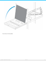
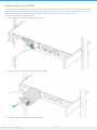
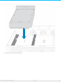
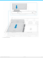
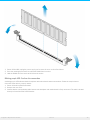
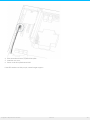
1
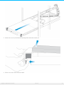
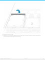
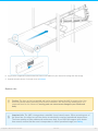
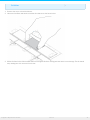
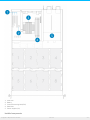
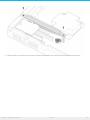
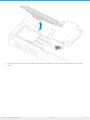
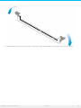
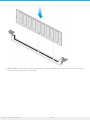
Seagate 8-Bay Rackmount NAS User Manual Cont ent s 1 Regulatory . . . . . . . . . . .Compliance . . . . . . . . . . . . . . . . . . . . . . . . . . . . . . . . . . . . . . . . . . . . . . . . . . . . . . . . . . . . . . . . . . . . . . . . .3 ....... 2 Introduction ....................................................................................4 ....... 3 Safety . . . . . . Guidelines ..............................................................................5 ....... 4 System . . . . . . . .Overview . . . . . . . . . . . . . . . . . . . . . . . . . . . . . . . . . . . . . . . . . . . . . . . . . . . . . . . . . . . . . . . . . . . . . . . . . . . .6 ....... 5 Setting . . . . . . . Up . . . . . . . . . . . . . . . . . . . . . . . . . . . . . . . . . . . . . . . . . . . . . . . . . . . . . . . . . . . . . . . . . . . . . . . . . . . . .8 ....... 6 Software . . . . . . . . . . . . . . . . . . . . . . . . . . . . . . . . . . . . . . . . . . . . . . . . . . . . . . . . . . . . . . . . . . . . . . . . . . . . . . . . . . . 10 ........ 7 Hardware . . . . . . . . . .Maintainance . . . . . . . . . . . . . . . . . . . . . . . . . . . . . . . . . . . . . . . . . . . . . . . . . . . . . . . . . . . . . . . . . . . . . . . . . 11 ........ . . . . . . . . . . . . . . . . . . . . . . . . . . . . . . . . . . . . . . . . . . . . . . . . . . . . . . . . . . . . . . . . . . . . . . . . . . . . . . . . . . . . . . . . . . . . . . . . . . . . . . . . . . . . . . . .11 Precautions .......... . . . . . .chassis Front . . . . . . . . . . . . . . . . . . . . . . . . . . . . . . . . . . . . . . . . . . . . . . . . . . . . . . . . . . . . . . . . . . . . . . . . . . . . . . . . . . . . . . . . . . . . . . . . . . . . . . . . . .11 .......... . . . . . .ve Remo . . the . . . .fro . . nt . . co . . .ver . . . . . . . . . . . . . . . . . . . . . . . . . . . . . . . . . . . . . . . . . . . . . . . . . . . . . . . . . . . . . . . . . . . . . . . . . . . . . . . . . . . . . . . . . . .11 .......... . . . .nt Fro . .chassis . . . . . . . info . . . .rmatio . . . . . n. . . . . . . . . . . . . . . . . . . . . . . . . . . . . . . . . . . . . . . . . . . . . . . . . . . . . . . . . . . . . . . . . . . . . . . . . . . . . . . . . . . . . . . .13 .......... . . . . . . . . a. .po Replace . . wer . . . . supply . . . . . . .unit . . . (PSU) . . . . . . . . . . . . . . . . . . . . . . . . . . . . . . . . . . . . . . . . . . . . . . . . . . . . . . . . . . . . . . . . . . . . . . . . . . . . . . . . . . . .15 .......... . . . . . . . . a. .hard Replace . . . . drive . . . . . . . . . . . . . . . . . . . . . . . . . . . . . . . . . . . . . . . . . . . . . . . . . . . . . . . . . . . . . . . . . . . . . . . . . . . . . . . . . . . . . . . . . . . . . . . .16 .......... . . . . . . . . a. .fan Replace . . . . . . . . . . . . . . . . . . . . . . . . . . . . . . . . . . . . . . . . . . . . . . . . . . . . . . . . . . . . . . . . . . . . . . . . . . . . . . . . . . . . . . . . . . . . . . . . . . . .20 .......... . . . . .chassis Rear . . . . . . . . . . . . . . . . . . . . . . . . . . . . . . . . . . . . . . . . . . . . . . . . . . . . . . . . . . . . . . . . . . . . . . . . . . . . . . . . . . . . . . . . . . . . . . . . . . . . . . . . . . .22 .......... . . . . . .ve Remo . . the . . . .rear . . . .co . . ver . . . . . . . . . . . . . . . . . . . . . . . . . . . . . . . . . . . . . . . . . . . . . . . . . . . . . . . . . . . . . . . . . . . . . . . . . . . . . . . . . . . . . . . . . . . .22 .......... . . . . . chassis Rear . . . . . . . info . . . .rmatio .....n . . . . . . . . . . . . . . . . . . . . . . . . . . . . . . . . . . . . . . . . . . . . . . . . . . . . . . . . . . . . . . . . . . . . . . . . . . . . . . . . . . . . . . . . .23 .......... . . . . . . . . co Installed . . .mpo . . . .nents . . . . . . . . . . . . . . . . . . . . . . . . . . . . . . . . . . . . . . . . . . . . . . . . . . . . . . . . . . . . . . . . . . . . . . . . . . . . . . . . . . . . . . . . . . . . . 24 .......... . . . . . . . . the Replace . . . battery . . . . . . . . . . . . . . . . . . . . . . . . . . . . . . . . . . . . . . . . . . . . . . . . . . . . . . . . . . . . . . . . . . . . . . . . . . . . . . . . . . . . . . . . . . . . . . . . . . .25 .......... . . . . . . . . . . . . . . . . . . . . . . . . . . . . . . . . . . . . . . . . . . . . . . . . . . . . . . . . . . . . . . . . . . . . . . . . . . . . . . . . . . . . . . . . . . . . . . . . . . . . . . . . . . . . . .28 RAM .......... . . . . . . . a. .DIMM Adding . . . . . .(RAM) . . . . . .to. .an . . .empty . . . . . slo . . . t. . . . . . . . . . . . . . . . . . . . . . . . . . . . . . . . . . . . . . . . . . . . . . . . . . . . . . . . . . . . . . . . . . . . . . . . . .28 .......... . . . . . .ve Remo . . a. .DIMM . . . . . .(RAM) . . . . . . . . . . . . . . . . . . . . . . . . . . . . . . . . . . . . . . . . . . . . . . . . . . . . . . . . . . . . . . . . . . . . . . . . . . . . . . . . . . . . . . . . . . . .31 .......... . . . . . . . .purple Blinking . . . . . . LED: . . . . .Confirm . . . . . . . .the . . .connection . . . . . . . . . . . . . . . . . . . . . . . . . . . . . . . . . . . . . . . . . . . . . . . . . . . . . . . . . . . . . . . . . . . . . . . . . . . . . . . . . .32 .......... 8 Getting . . . . . . . Help . . . . . . . . . . . . . . . . . . . . . . . . . . . . . . . . . . . . . . . . . . . . . . . . . . . . . . . . . . . . . . . . . . . . . . . . . . . . 34 ........ Regulatory Compliance Seagate 8-Bay Rackmo unt NAS 1/21/15 3 Introduc on Seagate 8-Bay Rackmo unt NAS 1/21/15 4 Safety Guidelines Seagate 8-Bay Rackmo unt NAS 1/21/15 5 System Overview Seagate 8-Bay Rackmo unt NAS 1/21/15 6 Seagate 8-Bay Rackmo unt NAS 1/21/15 7 Se ng Up Seagate 8-Bay Rackmo unt NAS 1/21/15 8 Seagate 8-Bay Rackmo unt NAS 1/21/15 9 So ware Seagate 8-Bay Rackmo unt NAS 1/21/15 10 Hardware Maintainance The 8-bay Rackmount NAS has a front and rear chassis, each with its own cover. Review the details below for hardware module locations and, where applicable, replacement. Refer to the product's Warranty before performing any hardware repairs or maintenance that is not described in this manual. Precau ons Hot-swapping means that you can perform maintenance or upgrade hardware while the NAS is powered on. The 8-bay Rackmount NAS features three hot-swappable parts: hard drives; fans; and power supply units. Prior to performing hardware maintenance on other parts of the NAS (such as RAM and the battery), power off the product and disconnect the power from the power supply. Use NAS OS or a short push on the power button to shut down the NAS before unplugging the power cables. During operation, all provided hardware (including the installed drives in their frames) should remain in place for optimal air flow. Users with less than eight disks are not required to install empty disk trays in the enclosure. Airflow and fan performance are regulated by temperature. Observe all conventional ESD precautions when handling 8-bay Rackmount NAS parts. Avoid contact with backplane components and module connectors, etc. In most instances, the top cover should be removed only when the unit has been turned off and allowed to cool down. Potential hazards of opening the cover while the product is operating includes, but is not limited to, hot surfaces and exposed parts. Front chassis Remove the front cover 1. Power down the NAS using NAS OS and unplug the power supplies. Wait for the components to completely cool before moving to Step 2. 2. Slide the NAS toward you until it locks into position. Seagate 8-Bay Rackmo unt NAS 1/21/15 11 3. Release the cover by simultaneously pushing both front latches toward you. 4. Lift the cover and remove it from the NAS. Seagate 8-Bay Rackmo unt NAS 1/21/15 12 Front chassis informa on Seagate 8-Bay Rackmo unt NAS 1/21/15 13 1. 2. 3. 4. Fans (x3) Frame 1, hard drives 1 - 4 Hard drive LEDs; SATA connections Frame 2, hard drives 5 - 8 Seagate 8-Bay Rackmo unt NAS 1/21/15 14 Replace a power supply unit (PSU) For optimal power management, the power load for the NAS is shared between the two PSU. If one should fail, all power will automatically run from the active PSU, guaranteeing continuous NAS operation. To help extend the lifetime of your hardware, make certain to replace a failed PSU as soon as possible. Follow the instructions below to replace a PSU: 1. Locate the PSU on the rear of the NAS. 2. Unlock the PSU by pushing its latch toward the handle. 3. Remove the PSU by pulling the handle away from the NAS. 4. Insert the replacement PSU into the empty PSU slot. Seagate 8-Bay Rackmo unt NAS 1/21/15 15 Replace a hard drive If a failed hard drive is under warranty, make certain to contact Seagate customer support to receive a replacement disk. When adding or replacing hard drives, consider using Seagate hard drives that are optimized for use with your 8-bay Rackmount NAS. See Seagate Enterprise Drives for further information. Important info: Replace a faulty drive with a drive of equal or greater capacity. When handling drives, make sure that they are placed (and stored) on a cushioned surface. Important info: When following the instructions below, make certain to place the new or replacement disk on the drive guides before connecting the ends to the SATA ports. Attaching the drive to the SATA ports before placing it on the guides will damage the SATA connections. 1. Power down the system, unplug the power supply, and remove the cover as described above. 2. Push the disk’s lock button to open the latch. 3. Place the disk on the NAS’s hard drive guides. Confirm that the disk is correctly aligned on the guides by gently pushing it away from the SATA connection. Seagate 8-Bay Rackmo unt NAS 1/21/15 16 4. Slide the disk into the SATA connection. Seagate 8-Bay Rackmo unt NAS 1/21/15 17 5. Close the disk’s latch. Seagate 8-Bay Rackmo unt NAS 1/21/15 18 6. Repeat the steps for each disk. 7. Replace the cover and slide the NAS into the rack. To unlock the rails, pull the rail fasteners on each side toward you. Secure the NAS to the rack using the two front screws. Seagate 8-Bay Rackmo unt NAS 1/21/15 19 8. Log on to the Seagate 8-bay Rackmount NAS from a workstation on your network to manage the new storage. 9. Rebuild the NAS volume. For details, refer to Software . Replace a fan Caution: The fans are hot-swappable and can be replaced when the NAS is powered on. You must use caution when removing a fan. In most instances, the fan will stop rotating once it is removed from its slot. However, moving parts can cause severe damage to your hands and body. Important info: The NAS is temperature controlled via an internal sensor. When removing one of the three fans, the other two will turn faster to maintain the required operational temperature. The faster rotation will be sudden and can become loud. If your NAS fans appear to be louder than normal, confirm that the room's temperature is within operational range (see Safety Seagate 8-Bay Rackmo unt NAS 1/21/15 20 Guidelines ). 1. Remove the cover as described above. 2. Using your forefinger and thumb, pinch the clips that secure the fan to its slot. 3. Lift the fan from its slot. Show caution when removing the fan since moving parts can cause severe damage. The fan should stop rotating once it is removed from its slot. Seagate 8-Bay Rackmo unt NAS 1/21/15 21 4. Insert the replacement fan into the empty slot. Rear chassis Remove the rear cover 1. Power off, unplug the power supplies, then wait for the components to completely cool. 2. Slide the NAS toward you until it locks into position. 3. Remove the two screws on the rear cover. Seagate 8-Bay Rackmo unt NAS 1/21/15 22 4. Slide the cover toward the rack and remove it from the NAS. Rear chassis informa on Seagate 8-Bay Rackmo unt NAS 1/21/15 23 1. 2. 3. 4. 5. PCIe slots Battery Central Processing Unit (CPU) RAM slots Power supplies (x2) Installed components Seagate 8-Bay Rackmo unt NAS 1/21/15 24 The rear chassis is shipped with the following: 1. PCIe: SATA extender (do not remove the SATA extender or add third-party PCIe boards to the NAS) 2. Battery: 3V Lithium Battery (CR2032) 3. CPU: Intel® Ivy Bridge 2.3GHz 4. RAM: 4GB DDR3 DIMM ECC (x1) 5. Power supplies: 100 to 240 VAC, 50 to 60 Hz (x2) Replace the ba ery The battery is located next to the PCIe slots and protected by the extension card support. To remove the extension card support, you will need a Torx screwdriver with a T6 point. Use caution when replacing the battery. There is a strong risk of explosion if the battery is replaced by an incorrect type. 1. Power off the system, unplug the power supply, and remove the rear cover as described above. 2. Remove the screws from the extension card support. Seagate 8-Bay Rackmo unt NAS 1/21/15 25 3. Gently unfasten the extension card support from the extension card and remove it to provide access to the battery. Seagate 8-Bay Rackmo unt NAS 1/21/15 26 4. Use one hand to press the battery's retaining clip away from the batter and use the other hand to lift the battery from its socket. Seagate 8-Bay Rackmo unt NAS 1/21/15 27 5. 6. 7. 8. Insert the replacement battery into the battery socket. Connect the extension card support to the extension card and fasten its screws. Replace the rear cover and connect the power supply cables. Power on the NAS. Make certain to dispose of used batteries according to the applicable laws for your region. RAM Adding a DIMM (RAM) to an empty slot 1. Power off the NAS, unplug the power supply, and remove the cover as described above. 2. Locate an empty DIMM slot and press its retaining clips outward. Seagate 8-Bay Rackmo unt NAS 1/21/15 28 3. Align the DIMM on the slot's socket. Make certain that the edge of the DIMM's notch matches the key for the socket. Seagate 8-Bay Rackmo unt NAS 1/21/15 29 4. Hold the DIMM on both ends and carefully insert it into the socket. The DIMM is properly inserted when you cannot push it further and the retaining clips snap into place. Seagate 8-Bay Rackmo unt NAS 1/21/15 30 Important info: Always insert the DIMM vertically to avoid damaging the notch. You may have to apply a limited amount of force on the DIMM's edges when pushing it into the socket. Remove a DIMM (RAM) Seagate 8-Bay Rackmo unt NAS 1/21/15 31 1. Power off the NAS, unplug the power supply, and remove the cover as described above. 2. Press the retaining clips outward to unlock the DIMM from its socket. 3. Hold the DIMM on its two ends and lift it from the socket. Blinking purple LED: Confirm the connec on A blinking purple LED indicates that the backplane and motherboard cannot communicate. Follow the steps below to determine if the cable is properly seated: 1. Power off the 8-bay Rackmount NAS. 2. Remove the rear cover. 3. Confirm that the communication cable between the backplane and motherboard is firmly connected. The cable is located directly in front of the PCIe SATA Extender. Seagate 8-Bay Rackmo unt NAS 1/21/15 32 4. If the connection is loose, try to fix it into place. 5. Install the rear cover. 6. Power on the 8-bay Rackmount NAS. If the LED continues to blink purple, contact Seagate support. Seagate 8-Bay Rackmo unt NAS 1/21/15 33 Ge ng Help Seagate 8-Bay Rackmo unt NAS 1/21/15 34