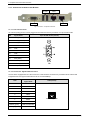
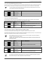
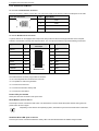
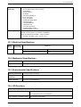
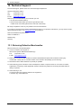
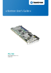
1
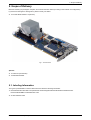
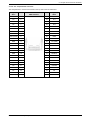
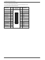
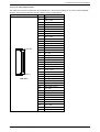
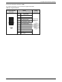
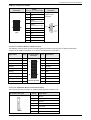
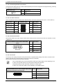
9. Jumpers and Connectors Overview
9.1.2. Jumpers on the PCI-960
The jumpers on the PCI-960 allow you to configure your CPU card according to the needs of your applications.
In order to change a jumper setting, turn off the computer by use of the ATX-power supply switch. If
your power supply has no On/Off switch, disconnect the main power source. Otherwise, the board
could be damaged.
The following examples show the conventions used in this section.
Jumper Open
1
2
1
2
Jumper Closed
9.1.2.1. JP4: Jumper for CompactFlash™ Card Selection as Master or Slave
This jumper is used to connect the CompactFlash™ as master or slave device on the IDE.
JP4: Pin Row; DIP 2-pin
Setting
Function
1
2
Pin 1-2
Closed
Master
2
Pin 1-2
Open(Default)
Slave
1
When connecting a CompactFlash on J8 (IDE port), make sure that you configure one device as master
and the other as slave. Two master devices (or two slave devices) must not be installed on the IDE
channel at the same time.
If using CF, only one device is supported by J8.
9.1.2.2. JP6: Jumper for RTC Reset (Clear CMOS Content)
This jumper allows you to clear the data (such as system password, date, time, and system setup parameters) in CMOS.
In order to change a jumper setting, please turn off the computer and unplug the power source to the
board. Otherwise, the board could be damaged.
The board might not start with this jumper in “closed” position.
JP6: Pin Row,
DIP 2-pin
Setting
Function
2
Pin 1-2
Open (Default)
Normal Operation
1
1
2
Pin 1-2
Short/Closed
Clear CMOS
Content
For clearing of content, please wait 10 sec.
18
PCI-960 – User’s Manual (V1.02)