1
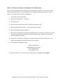
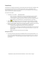
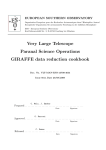
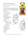
Leica Builder 503 Total Station i nstructions (Refer to either the User Manual or How‐T o Guide for specifics. The following is the most common setup.) Before Going in the Field Make sure the batteries are charged, and one is installed in the door on the left side. The battery compartment w ill hold different size batteries; we have two of the smaller ones, Leica ty pe GEB211 Li Ion 7.4V/2.2 Ah. mounted in the compartment Probably should make sure a flash drive is on the right side. Tour of the Instrument a) Compartment for USB memory stick & USB cable ports b) Bluetooth antenna c) Alignment sight d) Detachable carrying handle e) Telescope with integrated EDM (electronic distance meter) f) Vertical control knob g) On/Off key h) Switch key – we probably don’t need to use this: Top: laser pointer toggle Bottom: switch between Measure/record, All in 1, and Measure i) Horizontal control knob j) Optional second keyboard (not on our unit) k) Telescope focusing ring l) Eyepiece; focusing graticule m) Battery holder n) Serial interface o) Footscrew p) Display q) Keyboard Compiled by Jerry Davis, SFSU Institute for GIScience. Version 13‐Oct‐14. Page 1 Interface and Settings a) Page key: Changes tab between CONFIG, TRANSIT, PROG and DATA b) Navigation key Moves focus onscreen Starts edit mode for fields Control the input bar c) Escape key Leaves the current menu d) Light e) Function keys (work with choices shown onscreen) f) Keypad g) EDM key (short): access EDM settings (long): toggle between red‐dot (reflectorless shooting) and prism h) LED flashes once if EDM setting is changed, or when measurement is taken: White: EDM prism mode Red: EDM red dot mode (reflectorless) Prism Settings: Press the EDM key short to access this (not in TRANSIT, PROG or DATA mode) Using the Seco Prism with a ‐30 mm offset: For an offset off ‐30 mm, what we need to do is to set the prism constant to ‐30 mm, by using the EDM button to go to EDM Settings, to get to the Prism Constant setting, and change that. There's another setting for Prism Type, but we set that to User, since non‐Leica prisms are not shown on the list. Compiled by Jerry Davis, SFSU Institute for GIScience. Version 13‐Oct‐14. Page 2 Initial Setup: Leveling 1. Set up the tripod, either over a known point, or anywhere. a. If you are starting from scratch and don’t care about getting things into standard coordinates, it doesn’t matter. b. If you want to tie to benchmarks, they will need to be visible; if you can set up on one (not easy), this is the most accurate method. c. Get it somewhat close to level. 2. Carefully attach the total station on the 5/8” screw mount. 3. Close the case to keep out moisture and stuff. 4. Rotate the instrument parallel to two of the leveling screws, with the control panel thus parallel and facing you, as shown in the picture. 5. Roughly level the instrument using the circular level. a. For side‐to‐side leveling, turn both leveling screws on the parallel in opposite directions, by turning them both in or both out. b. For front‐to‐back leveling, turn the single screw at the back. 6. Turn on the instrument with the red button on the right. 7. If you are mounting over a benchmark, you will need to make sure you in the right place, by checking the red laser pointer. You may be able to move the instrument around on the tripod surface by loosening the screw a bit and repositioning it over the benchmark. You may also have to move the tripod, and redo the rough leveling. 8. You’ll get to a leveling window, and you can follow its directions with the leveling screws. When all three points are checked, it’s leveled. Import Previous Data (like control points) Use the DATA area to import previous jobs (in GSI format), which might include coordinates for control points (benchmarks) you’ve established before. You will probably want both: Fixpoints: Data points entered in as coordinates, thus do not include measurements used to derive them Measurements: Like fixpoints, these will have coordinates, so can be used for new benchmarks, but the “slope” measurements (angles and distance) are included as well. Compiled by Jerry Davis, SFSU Institute for GIScience. Version 13‐Oct‐14. Page 3 Establishing Coordinates and Orientation For most surveys, we will want to be in an absolute, projected coordinate system like UTM or State Plane. When you set up the instrument, it does not yet have its coordinate position, nor does it know its orientation. There are a few ways to establish this, using either permanent or temporary control points. You will need at least two, unless you also have a distant feature for which you know direction accurately. Permanent and monumented control points are called benchmarks, and may have been placed by geodesists as a brass plate, or as a surveying benchmark nail with an aluminum tag, or a rebar established by GPS or previous survey hammered into the ground, or maybe are a part of a concrete structure like a bridge or building; in any event, you need to know their position in the given coordinate system. Option 1: Setting up over a Control Point and Sighting to One Point This is the most accurate method, but is a bit tricky to set up, mainly in that it requires that you be able to set up directly over a benchmark. See: User Manual 9.3.2 “Establish Coordinates – Over Known Point”, or How to Guide 1.4 “Set Up over One Known Point with Second Known Point”. 1. Make sure you are directly over the benchmark, using the laser plummet: when the instrument is first on, until it’s fully leveled, a red laser dot will be visible on the ground directly below the instrument. If it’s not, you’ll need to reposition the tripod, roughly level and check again. The laser plummet will turn off after you’ve ok’d the accurate (on‐screen) leveling. The hard part is repositioning the tripod; once you’re close, you can loosen the screw mount and move the instrument a bit over the flat tripod head, then tighten once you’re directly over the point. 2. Use the menu button to go to PROG, press SETUP, select Coordinates… and Over Known Station… 3. Enter Height of the Instrument (hi), after measuring this with a tape – there’s a mark on each side, on the door of each compartment; and the Height of the Rod (hr), which for the little rod in the case is 1.3 m, then press OK. 4. Either select a station if you have one stored, or use NEW PT to enter its id and coordinates. 5. Select Orientation Method, either as a Manual Angle Setting (maybe from a compass, though this is not very accurate)or a Known Backsight Point. We’ll assume we have the latter. 6. Select Backsight Point, OK, Measure. Message: Station and Orientation will be changed and set NO – NEXT PT – YES 8. Alternatively, if you know an accurate azimuth to a distance point, use “Manual Angle Setting” for a backsight. 7. If you do another point and measure it, again only the angle will be measured, and an angular error will be displayed. If you’re not ok with it, you can REDO. Note that you can toggle between ANG and DIST errors. Once you OK this, you’ll again have the choice to add NEXT PT or YES to accept the setup. Then you’re ready to survey points. Compiled by Jerry Davis, SFSU Institute for GIScience. Version 13‐Oct‐14. Page 4 Option 2: Setting up “Anywhere” by Sighting to Two or More Points This is the easiest method, and lets you put the instrument where you want it, as long as you can sight to two or more control points. See: User Manual 9.3.3 “Establish Coordinates Anywhere” ; How to Guide 1.3 “Set Up Anywhere with Given Coordinates”) 1. Set up within sight of benchmarks. 2. PROG, SETUP, Coordinates…, Anywhere… 3. Enter hi & hr, OK 4. Select First Point: Either enter data, or select from saved points, OK 5. Measure (and Record) First Point ….[do we really need to record?] 6. Select Second Point, Measure & Record 7. With 2 points, a plausibility check will be displayed, based on the distance. At this point, you can say Yes to be done with the setup, No to measure the point again, or NEXT PT to use another point to improve the accuracy. 8. If you three or more points, you’ll get an assessment of accuracy of each of the points. Once you OK, you’ll again have the option of OK to accept or REDO. 9. A message will be displayed that says Station and Orientation STANYAN005 (or some name) will be changed and set. NO ‐‐ NEXT PT ‐‐ YES 10. Once you’re done, you’re ready to start recording points: Use APPL to select As Built… Compiled by Jerry Davis, SFSU Institute for GIScience. Version 13‐Oct‐14. Page 5 Surveying Points The best program to measure XYZ points is As Built. In contrast, Layout would be for placing points at known locations, like you might do if you were building something from a plan. Angle & Distance would be used if you want to just use the readings of horizontal & vertical angles and distance. Prism vs. other points (like ground points): EDM Type: prism or red dot. I'm assuming that red dot refers to any non‐prism points. Press the EDM key long to toggle between red dot and prism. Remember to also change the rod height (see below) to zero for red‐dot points. Setting the prism (rod) height during a survey: You may need to do this during any survey, such as when you need to extend the rod for visibility. You’ll also want to use this if you go to red‐dot. While surveying, go to SETUP, then Height to change any setting, including hr height of the rod. Compiled by Jerry Davis, SFSU Institute for GIScience. Version 13‐Oct‐14. Page 6 Stream Survey A total station is an excellent instrument for a survey under riparian cover where GPS is ineffective. We just need to get it oriented and into a coordinate system (which may be a challenge due to GPS benchmarking limitations). We can use a prism & pole to survey streambed points and control points, and then the reflectorless mode for many details. The modes to know about: User Manual 10.3 “As Built”. PROG/APPL/As Built… o Use Pt: for point id. Probably easiest to use just one prefix for the project, and let it increment a number. It’s not very easy to change this for different feature types. o In your notebook: Carefully record info you’ll need for each point, probably the type of point (thalweg, terrace, left bankfull, etc.), and include the point in your sketch. long to toggle between prism for control points and streambed (e.g. thalweg) EDM key points, and red dot for reflectorless points. Go to SETTINGS … Height to change the rod height. Measure and Record Mode. Might initially set to Measure/Record, to make sure you have the id numbering system down. Then after you’re comfortable with it, change to All in 1. o To measure a tree and get the center point, use a prism, with this set to Measure/Record: The distance is measured first at the right distance (on the side of the tree), then move to the middle of the trunk facing you to click Record – only then is the angle recorded. o Might also be used to measure the corner of a building. Moving the instrument First set up at least two control points to backsight to from the next instrument position. The most accurate method would establish one as the new instrument position, but it’s a hassle to set up the tripod over it. So maybe setting up three points to sight to, to get an error check, is more efficient. Compiled by Jerry Davis, SFSU Institute for GIScience. Version 13‐Oct‐14. Page 7 Saving your data The instrument can save both its data in various formats to a USB flash drive you can use to transfer the data to your computer. 1. From the total station, export the data to the flash drive, using DATA: IMP/EXP: o Exchange Mode: Export o Data Type: Meas.&Fixpoints o Job: Select the job you want to export (it won’t necessarily be the recent one) o Format IDEX… (to import later, you’ll also want to save a GSI file) 2. Shut the total station down, and remove the flash drive. 3. Copy the .idx files from the flash drive to your computer. Two comma‐delimited files will be saved in the Data folder: F_name.IDX and M_name.IDX, where “name” is the job name, and they can be read into Excel as comma‐delimited. Note that the file will include not only the xyz points (in the DATABASE section), but also the raw angle (Hz & Vz) and slope distance (SDist) readings in the THEODOLITE section. Reading data into Excel The IDEX format data is in text format, so can be edited with a text editor. However, it’s going to be most useful after bringing it into Excel, and that’s going to require a bit of text editing (or programming a script, but it’s pretty easy to do the text editing), then there’s some work in Excel to make it work: 1. Open the document named M_?????.IDX, where ????? is what you named the job, in a text editor like Notepad, Notepad++, TextPad. Not Word. 2. Delete the section called HEADER, and all the way up to the first field name, probably called PointNo. Then delete the closing parenthesis at the end of the first field name. Thus your first line should probably be: PointNo, PointID, East, North, Elevation, Code, Date, CLASS 3. Delete all the stuff at the end of the file after your list of points. This might start with “THEMINFO” and include the sections “METEO” and “THEODOLITE”. You basically want to end up with a single line of fields and x lines of coordinate data. 4. Save the file as ending with .csv. 5. Open the file in Excel. 6. The E, N and Z values won’t work directly as numbers until you convert them from text. They will also have spaces and maybe hidden characters that prevent them being used, so the best solution is to create a new column of E, N, and Z values, using the function =VALUE(CLEAN(C2)) for E, =VALUE(CLEAN(D2)) for N, and =VALUE(CLEAN(E2)) for Z. The CLEAN function removes superfluous characters and VALUE converts text to numbers. Compiled by Jerry Davis, SFSU Institute for GIScience. Version 13‐Oct‐14. Page 8 Adjusting (calibrating) the instrument Any instrument needs calibrating, and there is a way to calibrate the total station using a forward & reverse reading process. This is very easy to do, taking about 10 or 15 minutes if you have the right conditions, and should be done: • • • • • • Before the first use Before every high precision survey After rough or long transportations After long working periods After long storage periods If the temperature difference between current environment and the temperature at the last calibration is more than 20°C The right conditions needed: • Not too sunny conditions, with stable temperature. If it’s sunny, use an umbrella to shade the instrument. • Two points 100 m apart, not more than 5° vertical angle apart. You might be able to measure this with the total station of course, or use a survey tape. The process: 1. Set up the instrument and carefully level it; this will require turning it on for internal leveling as usual. Before starting to work, acclimate the instrument to the ambient temperature, at least 15 minutes from storage temperature. 2. Set the mode to TRANSIT 3. Press ESC for about 5 seconds until SYSTEM INFO is active. 4. Press CALIBR. 5. Press NEW. 6. Press MEASURE to measure to the target. 7. Rotate the target 180° vertically and horizontally to take a reverse reading. 8. (It’ll be a bit awkward because the display is on the wrong side, but…) Press MEASURE to measure the same target again and calculate the instrument errors. The old and new adjustment results are shown. 9. Press SET to set new adjustment data, or ESC to quit without setting the adjustment data if you’re not happy with it. Compiled by Jerry Davis, SFSU Institute for GIScience. Version 13‐Oct‐14. Page 9