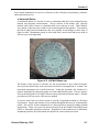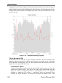
1
Section V Control Surveys Table of Contents A. Geodesy .................................................................................................................V-3 1. General ...............................................................................................................V-3 2. Control Datums ...................................................................................................V-6 a. Horizontal Datum ...........................................................................................V-7 b. Vertical Datum ...............................................................................................V-9 3. Coordinate Systems..........................................................................................V-12 4. State Plane Zones ............................................................................................V-14 a. State Plane Coordinates ..............................................................................V-17 b. Surface Coordinates ....................................................................................V-18 5. Azimuths ...........................................................................................................V-21 a. Azimuth References ....................................................................................V-21 b. Forward and Back Azimuths ........................................................................V-23 B. GPS Surveying .....................................................................................................V-23 1. The Global Positioning System .........................................................................V-24 2. A Brief History of GPS ......................................................................................V-25 3. Global Navigation Satellite Systems .................................................................V-26 4. How GPS Works ...............................................................................................V-27 a. Measuring Distance .....................................................................................V-27 b. Signal Timing ...............................................................................................V-28 5. The GPS Signal ................................................................................................V-28 6. Satellite Geometry ............................................................................................V-29 7. Error Sources in GPS .......................................................................................V-30 a. Atmospheric Errors ......................................................................................V-30 b. Obstructed Signals and Multipath Errors .....................................................V-32 c. Satellite Errors .............................................................................................V-33 d. GPS Equipment Errors ................................................................................V-33 Control Surveys e. Human Errors ..............................................................................................V-33 8. GPS Accuracy...................................................................................................V-33 9. GPS Surveying Procedures ..............................................................................V-34 a. GPS Methods ..............................................................................................V-34 a. Equipment ...................................................................................................V-48 b. Weather Conditions .....................................................................................V-49 C. Differential Leveling ............................................................................................V-49 1. General .............................................................................................................V-49 2. Bench marks .....................................................................................................V-49 3. Procedures .......................................................................................................V-50 4. Instrument Person’s Duties ...............................................................................V-51 5. Rod Person’s Duties .........................................................................................V-51 D. Extendible Control Surveys ................................................................................V-51 1. Extendible Control Coordinates ........................................................................V-51 a. Method 1......................................................................................................V-51 b. Method 2......................................................................................................V-52 c. Method 3 ......................................................................................................V-54 2. Traverse adjustment .........................................................................................V-55 V-2 Revised February, 2015 Section V V. Control Surveys A. Geodesy 1. General Geodesy is the science of measuring and monitoring the size and shape of the Earth and the location of points on its surface. The National Geodetic Survey (NGS) is responsible for the development and maintenance of a national geodetic database. The database serves as the basis of measurement for navigation and mapping. The Earth’s shape is not quite spherical. It is slightly flattened at the poles and bulging at the equator. This equatorial “bulge” is caused by the rotation of the Earth. Irregularities in its surface such as mountains and valleys make modeling the surface impossible. An infinite amount of data would be needed to create an exact model. Due to this complexity, a simplified mathematical model of the Earth was created. To measure the Earth, geodesists use a theoretical surface called an ellipsoid. The ellipsoid is a mathematically defined surface around on the earth's center of mass that approximates the size and shape of the Earth. This ellipsoid is smooth and does not account for surface irregularities. It is created by rotating an ellipse around the shorter polar axis to match the Earth’s actual shape. Because of its relative simplicity, an ellipsoid is the preferred surface to perform geodetic network computations. Point coordinates such as latitude, longitude, and elevation are defined on the ellipsoid. Figure V-1. Reference ellipsoid and geoid. Revised February, 2015 V-3 Control Surveys While the ellipsoid gives a common reference, it is still only a mathematical concept. Geodesists often need to account for the undulating surface of the Earth. To meet this need, the geoid was created. A geoid is a theoretical surface perpendicular at every point to the direction of gravity. It is also commonly associated with mean sea level. Since the Earth’s mass is unevenly distributed, certain areas of the planet experience more gravitational “pull” than others. Figure V-1 is an illustration of the ellipsoid and geoid. Latitude is measured in a north-south direction and is expressed as degrees of departure parallel to the equator. The equator is defined to be 0° latitude and is the intersection of the Earth’s surface with the plane perpendicular to its axis of rotation. It is nearly equidistant from the North Pole and South Pole and divides the Earth into northern and southern hemispheres. Longitude is measured in an east-west direction and is expressed as degrees of departure from the prime meridian. The longitude of the prime meridian is arbitrarily set as 0° and passes through the Royal Observatory in Greenwich, England. The prime meridian and its opposite meridian (at 180° longitude) divide the Earth into the eastern and western hemispheres. The International Date Line closely follows the 180° longitudinal meridian, occasionally deviating around land masses and island groups. Figure V-2 is an illustration of latitudes and longitudes. Figure V-2. Latitudes and longitudes. V-4 Revised February, 2015 Section V Gravity is the force that pulls all objects in the universe toward each other. On Earth, gravity pulls all objects downward, toward the center of the planet. According to Newton’s Universal Law of Gravitation, the attraction between two bodies is stronger when their masses are larger and closer together. This rule applies to the Earth’s gravitational field as well. Because the Earth rotates and its mass and density vary at different locations on the planet, gravity also varies. The variation in Earth’s gravity is measured because it plays a major role in determining mean sea level. Elevations on the Earth’s surface are based on mean sea level. Knowing how gravity affects sea level helps geodesists make more accurate measurements. Generally, areas of the planet where gravitational forces are stronger, the mean sea level will be higher because the water will be “pulled” to these locations. Conversely, areas where the gravitational forces are weaker, the mean sea level will be lower. To measure the Earth’s gravity field, geodesists use instruments located in space and on land. In space, satellites gather data on gravitational changes as they pass over points on the Earth’s surface. On land, devices called gravimeters measure the gravitational pull on a suspended mass. With this data, geodesists can create detailed maps of gravitational fields and adjust existing elevations. Because of the variations in gravitational force, the geoidal surface is irregular, but considerably smoother than the actual surface. The geoid varies from 350 ft (107 m) below to 280 ft (85 m) above the reference ellipsoid. As shown in Figure V-3, areas in red and yellow indicate regions where the Earth’s gravitational pull is stronger. In these areas, the geoid is above the reference ellipsoid. Areas in green and blue indicate regions where the Earth’s gravity is weaker and the geoid is below the reference ellipsoid. Figure V-3. Global geoid undulations. Every topographic point on the Earth’s surface has an orthometric elevation defined as the height above mean sea level. Near coastal areas, mean sea level is determined with by tidal gauges. In areas far from the coast, mean sea level is determined by the geoid. The geoid is a theoretical surface used to closely approximate mean sea level. The orthometric elevation is the distance or height from the geoid to a point on the Earth’s surface, measured along the plumb line normal to the geoid. Each point also has an ellipsoid elevation which is the height of the surface above the reference ellipsoid. Geoid separation is defined as the distance Revised February, 2015 V-5 Control Surveys between the geoid and the ellipsoid at any given point. A positive value indicates that the geoid is above the ellipsoid while a negative value indicates that the geoid is below the ellipsoid. In Wyoming, the geoid separation ranges from -26 ft (-8 m) in the northwest corner to -62 ft (-19 m) in the southeast corner of the state. Every few years, the NGS uses the latest vertical measurement data to develop new geoid models. Each subsequent model is a better representation of the actual size and shape of the Earth. Because GPS elevations are related to the geoid, it is important to use the current version to achieve the highest level of accuracy. The latest model, Geoid 12A, supersedes the previous models, Geoid 12 and Geoid 09. Figure V-4 is an illustration of geoid, ellipsoid, and orthometric elevations. Figure V-4. Geodetic elevations. 2. Control Datums A datum is an established point, line, or surface used as a reference to describe the location of a point. In surveying and geodesy, a datum is a set of reference points on the Earth’s surface. These reference points are used to correlate measurements for the determination of horizontal and vertical positions. Because datums may be defined by differing points of origin, a specific location can have substantially different coordinates. There are hundreds of locally developed datums around the world, usually related to a convenient reference point. Contemporary datums, based on increasingly accurate measurements of the shape of the Earth, are intended to cover larger areas for measurement. A nationwide network of control monuments and bench marks provide the basis for horizontal and vertical datums. A horizontal datum is used to define latitude and longitude or northing and easting locations. A vertical datum is used to define elevations or depths. The horizontal and vertical positions of the monuments in the control network have been determined by precise geodetic control surveys. Subsequent control surveys use the established monuments and bench marks to develop local project control networks. These V-6 Revised February, 2015 Section V local control monuments are used as a reference for the collection of preliminary, cadastral, and construction surveys. a. Horizontal Datum A horizontal datum is a network of survey monuments that have been assigned precise latitude and longitude measurements. Survey stations in the datum were typically marked with a brass, bronze, or aluminum disk set in concrete or rock. These markers were placed so that surveyors could see one marked position from another. To maximize the line-of-sight between monuments, they were usually set on hilltops or other areas of high elevation. Monuments placed in areas with little vertical relief had towers built to aid surveyors in locating them. Figure V-5. USC&GS Brass cap. The datum is then used as a reference for the development of new control networks. Surveyors have historically used a procedure referred to as triangulation to “connect” the horizontal monuments into a unified network. Using this procedure, the location of a point is determined by measuring angles to it from other known points. The new point is fixed as the third point of a triangle with one known side and two known angles. Another procedure used by surveyors is the traverse method. A traverse starts from two known points to provide a beginning azimuth (or direction) and position. Angles and distances are measured throughout the traverse at intermediate points. The traverse is then completed at two known points to check the ending azimuth and position. Today, surveyors rely almost exclusively on the Global Positioning System (GPS) to determine monument positions. Regardless of the method used to determine monument positions, the observations are adjusted to correct misclosure errors. Revised February, 2015 V-7 Control Surveys (1) History In 1807, the U.S. Coast Survey was established to chart the country’s coast in the New York Bay area. Shortly thereafter, its mission changed to include surveys of the interior as the nation grew westward. In 1878 the agency was reorganized into the United States Coast and Geodetic Survey (USC&GS). The first coordinate reference system was established from geodetic surveys performed in 1816 and 1817. The reference system has evolved from the original 11 local markers to more than 250,000 monuments around the country. These stations support various activities such as: Topographic mapping Nautical and aeronautical charting Engineering and construction Public utility management Tectonic motion studies Environmental hazard analysis Geographic information systems Early surveys were often based on a local datum or reference system that was determined by astronomical observations. These surveys were performed to develop nautical charts of small areas. Many other local surveys were used to develop maps as the country expanded westward. It soon became apparent that a common set of reference points were needed. Without a common reference, maps and charts produced from these surveys would not be compatible. By 1900, a sufficient amount of observations were obtained to complete a national geodetic datum. The datum, containing approximately 2,500 monuments, was based on the Clarke 1866 reference ellipsoid. The datum became known as the U.S. Standard Datum of 1901. In 1913, the U.S. Standard Datum became known as the North American Datum (NAD) when the governments of Canada and Mexico adopted it. The geodetic center of the datum is a survey station named Meades Ranch. The monument is located in Kansas near the geographic center of the contiguous United States. In the 1920’s, the USC&GS expanded the national network to more than 25,000 survey monuments. This network established limited geodetic control in many areas that were not involved in the 1901 datum. These new observations were incorporated into an adjustment known as the North American Datum of 1927 (NAD 27). An increase in economic and scientific growth after World War II resulted in a need for accurate coordinate information. Development of distance measuring equipment and aerial photography enhanced the capabilities of geodesists, surveyors, and cartographers to provide more precise positional data. Satellite and remote sensing V-8 Revised February, 2015 Section V technology improved and was made available for civilian applications. Due to these innovations, it became apparent that the NAD 27 coordinates were not sufficiently accurate. To provide more accurate global mapping, improved geoids and geocentric ellipsoids were developed. Newer geoid models combined terrestrial surveying measurements with information gathered from space-based satellites. The geocentric ellipsoid models (centered about the Earth’s mass) more closely approximate the true size and shape of the Earth. Three ellipsoids of note are the World Geodetic System of 1972 (WGS 72), the Geodetic Reference System of 1980 (GRS 80), and the World Geodetic System of 1984 (WGS 84). The GRS 80 ellipsoid system was adopted by the International Union of Geodesy and Geophysics in 1979. The U.S. Department of Defense (DoD) used the WGS 72 ellipsoid for its worldwide navigation until 1986 when it switched to WGS 84. The WGS 84 ellipsoid was last revised in 2004. In 1970, the Federal Government underwent a reorganization that created the National Oceanic and Atmospheric Administration (NOAA). The USC&GS became known as the National Geodetic Survey (NGS) and was placed under NOAA. In 1971, the NGS began an adjustment of the North American Datum to meet the demands for increased positional accuracy. The development of the North American Datum of 1983 (NAD 83) included a readjustment of existing survey observations. The adjustment resulted in the publication of coordinate data for approximately 250,000 geodetic control markers throughout the United States. Just as there was a need to adjust the NAD 27 datum, there was also a need to revise the NAD 83 datum. Further improvements in the Global Positioning System (GPS) revealed inaccuracies in individual survey monuments. Recent versions of the North American Datum include NAD 83 (1993), NAD 83 (CORS), and NAD 83 (2007). The latest version is the NAD 83 (2011) datum. The shift between the various datums is not uniform across the United States. There isn’t a single value that can be applied to every latitude and longitude in an older datum. However, the NGS provides software that transforms geodetic coordinates between datums. NADCON is conversion program that converts latitude and longitude positions between the NAD 27 and NAD 83 datums. NADCON also converts horizontal positions between the NAD 83 datum and the NAD 83 (1993) datum. This conversion tool is available on the NGS website and can be accessed through the following link: http://www.ngs.noaa.gov/TOOLS. b. Vertical Datum A vertical datum is a collection of specific points on the Earth’s surface with known heights in relation to mean sea level. Near coastal areas, mean sea level is determined with a tide gauge. In areas far away from the shore, mean sea level is determined by the geoid. Bench marks in the vertical datum use a non-corrosive metal disk set in concrete or rock to mark elevations. The disks are similar to survey markers used to identify positions in Revised February, 2015 V-9 Control Surveys the horizontal datum. Beginning in 1978, the NGS introduced an improved bench mark into the National Vertical Control Network. The reference point for the elevation is the top of a stainless steel rod which is protected inside an aluminum casement. The rod, driven to refusal, is accessed by lifting a hinged cover. The bench mark is designed to prevent near-surface soil disturbances such as frost heave, soil shrinkage, and soil swelling. This is accomplished by encasing the rod in a lubricated sleeve to the depth of expected soil movement. Figure V-6. Modern NGS bench mark. The traditional method for establishing new elevations is differential leveling. This method uses a known elevation at one location to determine the elevation at another location. For further information on differential leveling, see part C in this Section. (1) History The U.S. Coast Survey established the first geodetic quality leveling route in the United States in 1856. The leveling survey was required for tide and current studies in the New York Bay and Hudson River. The USC&GS began the transcontinental level line in 1887 at bench mark ‘A’ in Hagerstown, Maryland. The survey followed the 39th parallel and reached the Pacific by 1904. By 1900, the vertical control network in the U.S. included 4,200 bench marks and more than 13,000 miles of geodetic leveling. Because the vertical networks in each area were usually fixed to a local reference, most of the data was not compatible. A single vertical datum was needed to link the level elevations. A vertical datum was created and referenced to local mean sea level. Mean sea level is the average (or mean) height of the ocean’s surface measured by tidal stations over a 19-year period. This time period, known as a tidal epoch, is a complete sun and moon cycle and V-10 Revised February, 2015 Section V accounts for the effects on ocean levels. Subsequent adjustments of the leveling network were performed by the USC&GS in 1903, 1907, and 1912. By the late 1920’s, over 60,000 miles of leveling data had been collected. Mean sea level was being measured at 26 tide gauges in the United States and Canada. The gauges were connected through tidal bench marks to an extensive leveling network throughout the United States. However, the height of mean sea level was found to vary slightly from one tidal gauge to another. In 1929, the USC&GS began a least-squares adjustment of all geodetic leveling data completed in the United States and Canada. Because of the variations in mean sea level, the network was adjusted to set the elevation of mean sea level at each tidal gauge to zero. This adjustment established the 1929 Sea Level Datum, to reference each bench mark elevation to mean sea level. The datum was later renamed the National Geodetic Vertical Datum of 1929 (NGVD 29). Since 1929, approximately 385,000 miles of leveling has been added to the National Geodetic Reference System (NGRS). Periodic discussions were held to determine the proper time for the inevitable adjustment. In the early 1970’s, NGS conducted an extensive inventory of the vertical control network. The search identified thousands of bench marks that had been destroyed. Many existing bench mark elevations were affected by: Changes in sea level Movement of the Earth’s crust Uplift due to postglacial rebound Ground subsidence resulting from the withdrawal of underground water and oil Beginning in 1977, the NGVD 29 datum was adjusted to remove inaccuracies and to correct distortions in the network adjustment. Much of the first-order NGS vertical control network had to be re-leveled. Damaged or destroyed monuments were replaced with newer, more stable deep-rod bench marks. Due to the local variations at each tidal station, mean sea level was based on a single tidal gauge located in Quebec. In 1991, the result of the vertical adjustment of new and old leveling data was released. This adjustment also included level runs completed in Mexico and Canada. This new datum, called the North American Vertical Datum of 1988 (NAVD 88), provides a more accurate vertical reference system. Similar to the horizontal datums, there isn’t an exact correlation or translation between vertical datums. VERTCOM is an NGS conversion program that computes orthometric height differences between the NGVD 29 and NAVD 88 datums. The conversion is determined for any location specified by latitude and longitude. This conversion tool is available on the NGS website and can be accessed through the following link: http://www.ngs.noaa.gov/TOOLS. Revised February, 2015 V-11 Control Surveys 3. Coordinate Systems A coordinate system is used to determine the position of any point relative to an origin. Two-dimensional (2-D) coordinate systems utilize a pair of coordinate values to define a location in a single plane. A three-dimensional (3-D) coordinate system uses three coordinates to define a location in three perpendicular planes. The Cartesian coordinate system, also known as the rectangular coordinate system, is used to determine the location of points in a plane. The plane is defined by a Y (north-south) axis and an X (east-west) axis. The axes intersect each other at right angles at a location defined as the origin. The perpendicular distance of any point from the north-south axis is the easting (x) coordinate. The perpendicular distance of any point from the east-west axis is the northing (y) coordinate. The position of a point within the coordinate system is expressed with easting and northing (x, y) values. Figure V-7. Two-dimensional coordinate system. V-12 Revised February, 2015 Section V The polar coordinate system is another coordinate system used to define points located in a single plane. The location of a point is determined by the angle and distance from the origin. The angular coordinate ( ) is the angle between the polar (X) axis and a line to the point. The radial coordinate (r) is the distance from the origin to the point. Polar coordinates can be converted to Cartesian coordinates using the sine and cosine trigonometric functions. Conversely, Cartesian coordinates can be converted to polar coordinates using the Pythagorean Theorem and the inverse of the tangent trigonometric function. ; ; Figure V-8. Polar coordinate system. Revised February, 2015 V-13 Control Surveys A three-dimensional (3-D) Cartesian coordinate system adds a third (Z) axis to provide another dimension of measurement. The perpendicular distance from the Z axis defines the elevation (z) of a point. The position of a point within the coordinate system is expressed with easting, northing, and elevation (x, y, z) values. Figure V-9. Three-dimensional coordinate system. 4. State Plane Zones The state plane coordinate system (SPCS) was established in 1933 by the United States Coast and Geodetic Survey (USC&GS). The USC&GS, now known as the National Geodetic Survey (NGS), developed the system to simplify geodetic calculations. Prior to the development of the SPCS, geodetic positions were given in latitudes and longitudes and involved complex computations on the surface of an ellipsoid. By ignoring the curvature of the Earth, the SPCS allows surveyors to use a rectangular coordinate system to define specific locations. The SPCS is a network of individual state plane zones designed for specific regions throughout the United States. Each zone has an independent rectangular (or Cartesian) coordinate system with its own point of origin. The zones were created by using map projections to transform geodetic coordinates on a curved surface to rectangular coordinates on a flat plane. Distortions between the curved surface and the plane are not evident for small areas. However, as the projection area becomes larger, the distortions become more apparent. V-14 Revised February, 2015 Section V Distortions in a map projection are defined as the difference between distances calculated on the ellipsoid compared to the state plane. A maximum distortion of 1 part in 10,000 was established for the system. To maintain accuracy, larger states were divided into smaller zones the boundaries of which typically follow county lines. Only the smallest of states contain one state plane zone. There are a total of 110 zones in the continental U.S., with 10 more in Alaska, and 5 in Hawaii. Figure V-10 is an illustration of the four Wyoming state plane zones. Figure V-10. Wyoming state plane zones. Revised February, 2015 V-15 Control Surveys Most state plane zones are based on either a transverse Mercator map projection or a Lambert conformal conic map projection. The map projection is centered about a longitudinal line referred to as the central meridian. The specific map projection is dependent on the shape and size of the state. States that are longer in the east-west direction are divided into similar shaped zones that are also longer in the east-west direction. These zones use the Lambert projection to superimpose an imaginary cone over the ellipsoid. The apex of the cone is aligned with the Earth’s rotational axis. Figure V-11 is an illustration of a Lambert conformal conic projection. Figure V-11. Lambert conformal conic projection. States that are longer in the north-south direction are divided into zones that are also longer in the north-south direction. These zones use the transverse Mercator projection to superimpose an imaginary cylinder over the ellipsoid. The axis of the cylinder lies in the Earth’s equatorial plane. Figure V-12 is an illustration of a transverse Mercator map projection. All four Wyoming state plane zones are transverse Mercator projections. Either map projection intersects the ellipsoid along two lines, called secants. Along the secant lines, distortions between the curved surface and the plane are essentially zero. However, distortions increase as the distance from the secant lines increase. To maximize the accuracy of each zone, the width of either projection is limited to 158 miles (254 km). V-16 Revised February, 2015 Section V Also, the secant lines are positioned such that 2/3 of the zone lies between them and 1/6 of the zone lies outside. Figure V-12. Transverse Mercator projection. a. State Plane Coordinates To convert geodetic positions from the ellipsoid to a plane, points are first mathematically projected onto an imaginary surface. This surface is then laid out flat without further distortion in shape or size. A rectangular grid is superimposed over the flat surface to establish x and y state plane coordinates. Easting coordinates increase from west to east and are measured as the distance from the origin. The northing coordinates increase from south to north and are measured as the distance from the origin. The x and y coordinate values assigned to the grid’s origin are termed “false easting” and “false northing”. The grid origin is located south of each state plane zone to assure that the northing coordinates are positive. The easting coordinate at the origin is assigned a sufficiently large number to assure that these values remain positive. As mentioned earlier, each state plane zone has its own independent coordinate system. The easting and northing coordinates in adjacent zones are sufficiently different in magnitude to avoid confusing the coordinates. Revised February, 2015 V-17 Control Surveys State Plane Zone East East Central West Central West Zone Number 4901 4902 4903 4904 Central Meridian Longitude 105°10’00” 107°20’00” 108°45’00” 110°05’00” Latitude Of Origin 40°30’00” 40°30’00” 40°30’00” 40°30’00” False Easting (m) 200,000 400,000 600,000 800,000 False Northing (m) 0 100,000 0 100,000 Zone Width 3°00’00” 3°00’00” 3°00’00” 3°00’00” Table V-1. Wyoming state plane zone properties. b. Surface Coordinates A distance measured between two points on the Earth’s surface will differ from a distance calculated between the same two points on the state plane. An adjustment of the surface coordinates becomes necessary for these distances to match. It is important to remember that a particular adjustment is only valid over a relatively small area. The magnitude of the adjustment depends on the elevation and location within the state plane zone. All surveys utilizing project control monuments are based on surface (or ground) coordinates. This is necessary to produce mapping on a surface that matches the ground on which the project will be designed and constructed. The use of scaling factors is used to equate ellipsoid, grid plane, and ground distances. Figure V-13. Grid, ellipsoid, and surface distances. V-18 Revised February, 2015 Section V One component of the adjustment involves the projection of positions from a curved surface to a flat plane. A grid scale factor is used to convert positions located on the ellipsoid to positions on the state plane grid. It is a dimensionless scale factor that reflects the difference between distances on the ellipsoid and distances on a plane. The grid scale factor varies across the state plane zone and is dependent on the distance from the central meridian in the east-west direction. It is less than 1.0 at the central meridian, equal to 1.0 at the secant lines, and greater than 1.0 when the state plane is above the ellipsoid. For each Wyoming state plane zone, the grid scale factor is 0.9999375 at the central meridian. This equates to a scale factor equal to 1 part in 16,000. Figure V-14. Grid scale factor. The other component of the conversion is a function of elevation. An elevation factor is another dimensionless scale factor used to convert distances. This scale factor is used to convert a distance on the ground to an equivalent distance projected onto the ellipsoid. The elevation factor varies as the elevation of the Earth’s surface changes. Revised February, 2015 V-19 Control Surveys As the ground elevation increases, the distance from the center of the Earth to its surface increases. This distance is equal to the radius of the Earth. As the radius increases, the corresponding arc length also increases. Thus, a distance measured on the ellipsoid is shorter than a corresponding distance measured on the ground due to the longer radius. A distance measured on the surface must be reduced in proportion to the change in radius between the ellipsoid and the surface. The grid and elevation factors for each project are determined from the adjusted project control positions by GPS post-processing software. The combined datum adjustment factor (DAF) is a product of the grid scale factor multiplied by the elevation factor. State plane coordinates are multiplied by the reciprocal of the DAF to determine corresponding surface coordinates. Each project control monument is “occupied” by GPS receivers in a series of static and rapid-static networks. The raw GPS data is then adjusted with proprietary postprocessing GPS software. Although combined factors are computed for each control monument, a single DAF is used for the entire project. This DAF is an average of the individual DAF values of each project control point. The single adjustment factor does not cause an appreciable loss in accuracy and will eliminate confusion caused by multiple factors. The DAF value is carried out to nine decimal places so that surface coordinates can be accurately calculated to the nearest ten-thousandth of a meter. Figure V-15. Scale factors. The purpose of the DAF is to keep surface coordinate computation errors less than 1:50,000 for the entire project. This equates to a linear error of less than 0.02 ft (0.006 m) in a 1000 ft (305 m) distance. Occasionally, the DAF for an individual control point will differ from the project DAF by more than 0.00002. When this happens, errors greater than 1:50,000 will occur. These situations typically take place on projects that are extremely long, have a considerable elevation difference, or run in a predominantly eastwest direction. The project may need to be broken into shorter lengths with a separate V-20 Revised February, 2015 Section V DAF for each segment. Splitting the project will keep the computational errors within acceptable standards. Project control monuments may have dual surface coordinates for each DAF where the project has been split. 5. Azimuths Azimuths are expressed as an angular measurement from a reference line or meridian to an observed line. One of the many interpretations of North is typically used as a reference, although a south reference has also been used. The angular measurement will range through a full circle, most commonly expressed as 0° to 360° measured clockwise from the reference. a. Azimuth References The most commonly used references are geodetic north, astronomic north, magnetic north, grid north, and an assumed north. (1) Geodetic North Geodetic north is defined at any point by a meridian that passes through the north and south geodetic poles. Surveys are typically based on the geodetic north reference unless otherwise specified. Geodetic north may also be referred to as geographic north. (2) Astronomic North Astronomic north is determined by a celestial body. Polaris (the North Star) is typically used to define this reference. Astronomic north is very close to geodetic north, and the two have sometimes been used interchangeably. (3) Magnetic North Magnetic north is based on magnetic or compass meridians which run through the magnetic north and south poles. In the northern hemisphere, magnetic north is the direction that a compass needle will point toward. The Earth’s magnetic poles are not at the same location as the geodetic poles and are constantly changing. Figure V-16. North references. Revised February, 2015 V-21 Control Surveys (4) Grid North Grid north at any point within a state plane zone is parallel to the central meridian. While geodetic north meridians converge at the poles, grid north remains parallel to the central meridian. Therefore, only at the central meridian will grid north point in the same direction as geodetic north. Figure V-17 is an illustration comparing geodetic north and grid north. Figure V-17. Geodetic and grid north. (5) Assumed North Assumed north is an arbitrary direction assigned to be 0°. V-22 Revised February, 2015 Section V b. Forward and Back Azimuths The direction of a given line is usually stated as an azimuth measured from its beginning point to an ending point. This is called the forward azimuth. Each line also has a corresponding back azimuth, which is the azimuth measured from its ending point back to the beginning point. The difference between the forward azimuth and the backward azimuth is always 180 degrees. Figure V-18. Forward and back azimuths. B. GPS Surveying The practical uses of GPS are more meaningful to the surveyor or engineer than the theory behind it. However, when performing a GPS survey, an understanding of the basic principles involved is important. Like any tool, GPS equipment is most effective when it is used in the proper situations. Planning, preparation, and an awareness of the capabilities and limitations of GPS are critical factors for a successful survey. Note: The methods of GPS surveying in this section apply only to preliminary surveys. For information on construction surveys or land surveys, consult the Construction Manual or the Right-of-Way Program. Surveying with GPS equipment has many advantages over conventional surveying methods: It is not necessary to have intervisibility between project control monuments. GPS collection can be used at any time, day or night, and in most weather conditions. GPS methods typically produce results with very high geodetic accuracy. Revised February, 2015 V-23 Control Surveys In general, more work can be accomplished in less time with fewer people. Using GPS equipment also has several disadvantages: GPS receivers require a clear view to a minimum of four satellites. Satellite signals may be blocked or deflected by buildings, trees, utility poles, etc. GPS cannot be used indoors and is difficult to use in urban environments, heavily wooded areas, or in mountainous terrain. The vertical component of GPS measurements may not meet established collection standards for features with critical elevation accuracies. Due to these limitations, it may be necessary in some survey applications to use an optical instrument by itself or in conjunction with GPS equipment. 1. The Global Positioning System The Global Positioning System (GPS) is a worldwide radio-navigation system. The system was originally intended to be used for military applications only. GPS technology has since evolved into a resource used by civilians for locating, navigating, tracking, mapping, and timing applications. The space segment, control segment, and user segment are key components of GPS. The space segment consists of a constellation of up to 32 satellites traveling in nearly circular orbital patterns. The exact number varies as older satellites are continually retired and replaced. The satellites are positioned in six Earth-centered orbital planes approximately 11,000 miles (17,700 km) above the surface of the Earth. The orbits are equally spaced about the equator at a 60 degree separation with an inclination of 55 degrees relative to the equator. Figure V-19. Satellite orbits. The orbital period of a GPS satellite is one-half of a sidereal day or 11 hours 58 minutes. Each satellite will arrive at a specific location above the Earth’s surface every 23 hours 56 V-24 Revised February, 2015 Section V minutes. Because satellite and Earth rotational periods are slightly different, each satellite will appear above the same location of the Earth four minutes earlier every day. Each satellite transmits a signal that gives its current position and time. The control segment consists of monitor stations, ground antennas, and a master control station. The National Geospatial-Intelligence Agency (NGA) operates a globally distributed network of automated GPS monitor stations. This network is positioned to allow each satellite to be observed by at least two monitor stations. Their primary mission is to collect observations from satellites in the GPS constellation. Each satellite’s operational health, ephemeris (altitude, speed, and position), and clock offsets are continually monitored. Figure V-20. Monitor and control station locations. The monitor stations send the satellite information to the master control station located at Schriever AFB in Colorado Springs, CO. The data is processed to identify positional or timing errors for each satellite. The updated ephemeris data and clock offset corrections are then transmitted to each satellite via ground antennas. The satellites incorporate these updates to ensure accurate orbital data is included into the signals sent to ground-based GPS receivers. The user segment includes the equipment used by civilian and military personnel to receive GPS signals. The GPS receiver equipment consists of an antenna and receiver. The antenna acquires the GPS signals while the receiver decodes the signals to determine position, velocity, and time. 2. A Brief History of GPS Trying to calculate a precise position on the Earth’s surface has always been a difficult problem to solve. Over the years various technologies have tried to simplify the task but every method had disadvantages. The United States Department of Defense (DoD) needed a very precise method of worldwide positioning. In the latter days of the arms race, targeting and hitting specific sites became very precise. But a target could only be hit if the exact launch point is known. However, the majority of the U.S. nuclear arsenal was at sea on submarines. The DoD had to find a way to allow the Revised February, 2015 V-25 Control Surveys subs to surface and calculate their exact position. With the development of the Global Positioning System, this was now possible. Figure V-21. GPS satellite. The Navigational Satellite Timing and Ranging (NAVSTAR) system is the official name for the positioning system used by the DoD. The first GPS satellite was launched in 1978 and a full constellation of 24 satellites were in orbit by 1994. The spacing of the satellites was arranged so that a minimum of five satellites are in view from every point on the globe. While each satellite has a designed life expectancy of approximately 10 years, replacements are continuously being built and launched. The satellites are powered by solar energy and use onboard batteries in the absence of solar power. Small rocket boosters are used to keep satellites in their intended orbit. 3. Global Navigation Satellite Systems A Global Navigation Satellite System (GNSS) provides autonomous positioning with global coverage. The coverage for each system is generally achieved by a constellation of 20 to 30 satellites spread between several orbital planes. Although each system varies, satellites generally orbit the Earth in 12 hours and travel in the middle Earth orbit at an altitude between 12,000 to 15,000 miles (19,300 to 24,100 km). The United States’ NAVSTAR Global Positioning System is the only fully operational GNSS. Currently, there are three other global navigational systems in the process of being developed and implemented. These navigation systems, when operational, will provide positional data that is complementary to the U.S. Global Positioning System. The Russian GLONASS system was a fully functional constellation developed in the days of the Soviet Union. With the fall of Communism, GLONASS fell into a state of disrepair leading to gaps in coverage and partial availability. The Russian Federation has since committed to completely restoring the navigational system. Currently, 24 of the 28 GLONASS satellites are fully operational. V-26 Revised February, 2015 Section V Galileo is the project name for the satellite navigation system being developed by the European Space Agency. Designed specifically for commercial and civilian use, Galileo is intended to provide a higher degree of navigational accuracy than is available with NAVSTAR or GLONASS. Currently, Galileo is in the initial deployment phase and is scheduled to have all 30 satellites in orbit by 2020. The Chinese are developing an extension to their regional navigational system, known as Compass. The current system replaces an earlier satellite system referred to as Beidou (Big Dipper). Compass became operational in China in December 2011, and expand into a global network by 2020. The global Compass system is proposed to utilize 30 orbiting satellites and five geostationary satellites. In the near future, these systems have the potential to provide a minimum of 75 satellites for civilian users. GPS receivers will be able to combine the signals from each system to greatly increase positional accuracy. However, older receivers will need to be upgraded or replaced to utilize these global navigational systems. 4. How GPS Works The GPS process utilizes orbiting satellites as reference points for determining locations on or near the Earth’s surface. By measuring the distance from a minimum of three different satellites, a ground-based GPS receiver can then determine its position. The receiver then uses a fourth measurement to another satellite to calibrate its internal clock. a. Measuring Distance The distance to an orbiting satellite is calculated by measuring the elapsed time for a signal sent from a satellite to arrive at a receiver. This method uses the equation distance equals velocity multiplied by travel time. Radio signals travel at the speed of light or roughly 186,000 miles (300,000 km) per second. The travel time of a signal emitted from a satellite directly overhead is approximately 0.06 seconds. Because the travel time of the radio signal is so short, very precise clocks are needed. The pseudo-random code (PRC) is a fundamental part of GPS. It is a digital code with a complicated sequence of “on” and “off” pulses. The signal is so complicated that it resembles random electrical noise. Since all satellites use the same frequency, this pattern ensures that a GPS receiver can distinguish each signal sent from every satellite. The complex digital code also makes the system more difficult to jam and gives the DoD a way to control access to the system. Each GPS satellite continuously broadcasts a signal with the time of day and its ephemeris (among other information). There is a very slight delay between the time the satellite broadcasts the signal to the time the receiver detects it. The amount of delay is equal to the travel time of the satellite’s signal. The distance to the satellite is then calculated by multiplying the delay by the speed of light. Using the GPS signals, a receiver calculates the range (distance to each satellite) to determine its position. When a single range is known, the receiver calculates its position as any point located on an imaginary sphere with the satellite at the center. The receiver Revised February, 2015 V-27 Control Surveys simultaneously generates an imaginary sphere with each visible satellite. By generating a sphere with three satellites, the receiver narrows its location to two possible points. Figure V-22 is an illustration of the intersection of these spheres. The receiver can typically dismiss one of the points leaving only one possible solution. However, to determine a precise position, a fourth satellite must be used. Figure V-22. Position determination. b. Signal Timing Each satellite in the constellation is equipped with an atomic clock. By using the oscillations of a cesium atom, these clocks are the most accurate form of timing ever developed. The atomic clocks installed in each GNSS satellite are synchronized with Universal Time established by the U.S. Naval Observatory. Measuring the travel time of the radio signal emitted by a satellite is the key to precise GPS positioning. As mentioned earlier, the radio signal is traveling at the speed of light. If the timing is off by only one thousandth of a second, an error of 186 miles (300 km) can result. For the system to work correctly, the receiver’s clock must be also be precisely synchronized. By making a fourth satellite measurement, the receiver can eliminate any clock inaccuracies. The distance from a receiver to a satellite is calculated from the radio signal travel time. If the receiver was perfectly synchronized with Universal Time, then each satellite range would intersect at a single point. But with an imperfect clock in the receiver, a fourth measurement will not intersect with the first three. The receiver then calculates a correction factor to apply to each timing measurement that allows all ranges to intersect at a single point. This correction synchronizes the receiver’s clock and is constantly repeated to keep the clock synchronized. 5. The GPS Signal GPS satellites emit radio signals on two carrier frequencies. The L1 frequency is 1575.42 V-28 Revised February, 2015 Section V MHz and transmits satellite status information and the pseudo-random code. The L2 frequency is 1227.60 MHz and transmits another, more precise pseudo-random code. The PRC carried by the L1 signal modulates at a 1 MHz rate and is called the Coarse/Acquisition (C/A) code. The C/A code is the basis for civilian GPS use. The second PRC carried by the L2 signal modulates at a 10 MHz rate and is called the Precise-code (P-code). This code is intended for military users and when encrypted is referred to as the Y-code. Currently, there are over 30 operational satellites in the GPS constellation. Additional satellites with modernized signals are continually being put into orbit. These satellites are capable of transmitting L2C signals (civilian signals on the satellite’s L2 carrier). The new L2C signal will make GPS observations even more reliable. However, a GPS receiver capable of tracking the L2C signal will be required. An entirely new L5 carrier is being transmitted on a new generation of satellites. The launching of these satellites began in 2007. With the L1, L2, L2C, and L5 carriers available, the capabilities of GPS systems should be significantly boosted and will provide more benefits for surveyors. In addition, the L5 signal will provide a higher power output than the other carriers. As a result, acquiring and tracking signals will be easier. As with the L2C signal, a GPS receiver capable of tracking the L5 signal will be required. 6. Satellite Geometry Dilution of precision (DOP) is a measure of satellite geometry as it relates to the spacing and position of every satellite above the mask angle. Several different types of DOP can be calculated. Time dilution of precision (TDOP) measures accuracy degradation as it relates to time. Vertical dilution of precision (VDOP) measures accuracy degradation as it relates to elevation. Horizontal dilution of precision (HDOP) measures accuracy degradation as it relates to latitude and longitude. Positional dilution of precision (PDOP) measures accuracy degradation as it relates to latitude, longitude, and elevation. Geometric dilution of precision (GDOP) measures accuracy degradation as it relates to latitude, longitude, elevation, and time. Lower DOP values occur when satellite constellations are evenly distributed throughout the visible sky. The most accurate positions will generally be achieved when GDOP values are 5.0 or lower. When GDOP values exceed 8.0, GPS data collection should be suspended. Software programs using the latest GPS almanac are used to predict DOP values for a specific location and time. When DOP values are known, GPS sessions may be scheduled to collect data during times of optimal DOP values. See Figure V-23 for an example of a satellite availability program. The GPS almanac is comprised of data transmitted from orbiting satellites regarding the operational status of the entire constellation. Orbital information for individual satellites is also included in the almanac. When an up-to-date almanac is loaded onto a receiver, it can acquire satellite signals and determine an initial position more quickly. Because atmospheric effects are increased for satellites closer to the horizon, an minimum elevation mask of 15 degrees should be set in each receiver. An elevation mask is the lowest elevation above the receiver’s horizon that satellite data is recorded. The receiver’s horizon Revised February, 2015 V-29 Control Surveys is defined by a level plane radiating out from the antenna. The receiver will not utilize a signal emitted from any satellites orbiting below this elevation. Most obstructions below the elevation mask can be ignored but multipath signals from a surface below the mask can still reach the antenna. Figure V-23. Satellite availability program. 7. Error Sources in GPS Measurement errors in GPS can never be completely eliminated. However, through proper planning, collection procedures, redundant measurements, and random checks most errors can be identified and mitigated. There are many external factors that adversely affect GPS signals and consequently the GPS survey. a. Atmospheric Errors Changes in atmospheric conditions alter the speed of GPS signals as they travel from the satellite to the Earth’s surface. Any delay in the signal causes measurement errors that affect the accuracy of calculated positions. Correcting these errors is a significant challenge to improving GPS accuracy. Atmospheric effects are minimized when satellites are directly overhead. The effects are increased for satellites closer to the V-30 Revised February, 2015 Section V horizon because the signal must pass through more of the Earth’s atmosphere. Once the receiver’s approximate location is known, mathematical models can be used to estimate and compensate for some of these errors. Figure V-24. Atmospheric disturbances. The ionosphere is a layer of the Earth’s atmosphere that ranges in altitude from 30 to 300 miles. This layer mainly consists of ionized or charged particles. Increased ionosphere disturbances are caused by solar particles and magnetic fields emitted by the sun. Any significant increase in solar activity can adversely affect GPS collections. Space weather conditions are posted on the National Oceanic and Atmospheric Administration (NOAA) website, http://www.swpc.noaa.gov. NOAA’s Space Weather Prediction Center (SWPC) provides warnings in three different categories; geomagnetic storms, solar radiation storms, and radio blackouts. GPS surveys should not be collected during severe solar weather events. Satellite signals passing through the ionosphere layer are subject to refraction which results in a delay of the GPS signal. The effects of the ionosphere for receivers less than 6 miles (10 km) are nearly equal for each receiver. However, when the receivers are greater than 6 miles apart, the ionosphere effect is not equal. Ionospheric modeling is accomplished by receivers with multi-channel tracking and dual frequency capabilities. While much of the error caused by the ionosphere can be removed through mathematical modeling, it is still one of the most significant error sources. The troposphere is the portion of the atmosphere closest to the Earth’s surface and is the densest layer of the atmosphere. The tropospheric effects are more localized and change more quickly than the ionospheric effects. However, errors caused by the troposphere are smaller than ionospheric errors. This layer is mainly comprised of water vapor and varies in temperature, pressure, and humidity. Because of this variability, errors are more difficult to predict and can only be approximated by a general calculation model. Atmospheric modeling is accomplished by receivers with dual frequency capabilities that compare the relative speeds of two different signals. Low-frequency signals get refracted or slowed more than high-frequency signals. By comparing the delays of the two Revised February, 2015 V-31 Control Surveys different carrier frequencies, L1 and L2, the atmospheric delays can be mitigated. b. Obstructed Signals and Multipath Errors Nearby obstructions can produce poor GPS results or can eliminate the use of GPS altogether. Overhead obstructions may block GPS signals completely or introduce multipath errors to limit the effective use of GPS equipment. Multipath errors result from a GPS signal that has reached the receiver’s antenna by more than one path. This is typically caused by a signal that has been reflected off of another surface before reaching the GPS antenna. When a reflected signal reaches the antenna, a position is calculated as if the signal traveled directly from the satellite. A positional error results because the receiver interprets the slightly longer travel time as a longer travel distance from the satellite. Figure V-25. Signal obstructions and multipath errors. When collecting GPS survey data, obstructions and multipath errors must be kept to a minimum at each receiver. Sources of obstructions and multipath include but are not limited to buildings, trees, vehicles, traffic signs, and overhead utility poles. These error sources can be minimized by following a few simple procedures: V-32 Be aware of the immediate surroundings and do not place the receiver near obstructions or reflective surfaces. Collect data for longer periods of time, with multiple sessions, and with substantially different satellite constellations. Raise the elevation mask to eliminate the source of the multipath. Use an antenna with a choke ring or ground plane to reduce the effects of multipath. Revised February, 2015 Section V c. Satellite Errors While the satellites utilize very accurate on-board atomic clocks and follow precise orbits, deviations are inevitable. These types of errors are the result of orbital drift and timing errors. The discrepancies translate into travel time measurement errors that adversely affect the position determination of the receiver. Although minor, these errors must be accounted for to achieve greater accuracy. The ephemeris data and clock offsets are continuously monitored by the GPS monitor stations. Any necessary corrections are sent back to the satellites to be included in their broadcasted signal. Positional errors occur because of the latency between the time of the actual occurrence of the deviation(s) and the time the corrections are computed and broadcasted. Because these errors are random in nature, the more satellites that are tracked, the more likely these satellites errors will cancel rather than compound. d. GPS Equipment Errors Poorly maintained GPS equipment may potentially introduce errors into the survey. Although not all errors caused by GPS equipment can be completely eliminated, they can be kept to a minimum. Internal and/or external batteries should be fully charged prior to GPS collections. Periodically check equipment cables and connectors. Memory cards should be periodically formatted to limit the chance of corruption and to ensure adequate storage space is available. Refer to the manufacturer’s guidelines regarding routine maintenance and calibration. e. Human Errors Perhaps the biggest and most unpredictable source of error is caused by the human element. Human errors are typically caused by inconsistent setup and collection procedures. Care should be taken while performing GPS surveys to minimize these types of errors. Examples of human error include but are not limited to the following: Incorrect reading or recording of antenna height measurements. Poor centering or tripod leveling procedures. Observing the wrong control point (e.g. setting up on a reference marker instead of the actual survey station). Using GPS equipment in areas where satellite signals may be blocked or deflected. Collecting GPS data with an inadequate number of satellites or an elevated GDOP/PDOP value. Relying on GPS measurements for critical elevations that may not meet established collection standards. Following established GPS setup and collection procedures will eliminate the majority of human errors. 8. GPS Accuracy As previously discussed, GPS accuracy is affected by a number of external factors. The accuracy of a GPS established position is also dependant on the type of receiver. Hand-held GPS receivers use an absolute position method to determine a location. This positioning Revised February, 2015 V-33 Control Surveys method is based on the receiver’s relationship to each satellite. Survey grade receivers use a relative position method to determine a location. This positioning method is based on the receiver’s relationship to each satellite and to other ground based receivers. Most hand-held GPS units establish absolute positions accurate to within 15 to 50 ft (5 to 15 m). Multi-channel, dual frequency receivers are typically able to achieve relative positional accuracies of 3 to 5 ft (0.9 to 1.5 m). Substantially greater accuracies are achieved when a receiver’s survey data is post-processed with another receiver’ data. Post-processing is a procedure used to adjust raw survey data to determine a solution for each occupied position. The receivers must run concurrently and include information from the same satellites. GPS generated positions are typically more accurate when two (or more) measurements are averaged. This is especially true when the measurements are separated by a time difference of three to four hours to include a different satellite constellation. A unique result will be produced from each observation thereby strengthening the overall solution. 9. GPS Surveying Procedures These specifications define procedures that shall be followed while performing GPS surveys by WYDOT personnel or contracted consultant surveyors. GPS technology is constantly undergoing advances with respect to hardware, firmware, and post-processing software. New and/or revised procedures for WYDOT will continually need to be developed within this section to reflect these changes. a. GPS Methods There exists a wide variety of GPS surveying methods. These methods differ in the type of equipment used, length of observation times, and accuracy attained. GPS methods that are most commonly used within WYDOT include but are not limited to HARN, static, rapid-static, and RTK surveys. All GPS surveys shall be referenced to the National Spatial Reference System (NSRS). Previously established WYDOT project control monuments tied to the NSRS are also acceptable for reference stations. The NSRS is a highly accurate network of survey monuments throughout the United States and is the primary source for geodetic control in Wyoming. The National Geodetic Survey (NGS) maintains the survey monuments and corresponding geodetic data within the NSRS. NGS and WYDOT survey monuments are fixed positions used to establish adjusted positions for subsequent control networks. Currently, horizontal positions are referenced to the NAD 83 (2011) horizontal datum. Vertical elevations are referenced to the NAVD 88 vertical datum. Information regarding survey marks in the national database can be accessed through the NGS website http://www.ngs.noaa.gov/cgi-bin/datasheet.prl. They provide ASCII text datasheets that contain information for each survey control station in the database. Datasheets for horizontal control stations show precise latitude and longitude. Datasheets for vertical control stations or bench marks show precise elevations. Other relevant data includes geoid height, state plane coordinates, and directions to the monument. Figure V26 is an example of an NGS data sheet. V-34 Revised February, 2015 Section V Revised February, 2015 V-35 Control Surveys Figure V-26. NGS data sheet. V-36 Revised February, 2015 Section V The NGS has requested that users of NSRS monuments complete an Online Mark Recovery Form. This form allows the surveyor to submit information regarding the location and condition of each survey marker. Monuments that have been destroyed or cannot be found should be reported. The Online Mark Recovery Form can be accessed through the NGS website: http://www.ngs.noaa.gov/ngs-cgi-bin/recvy_entry_www.prl. (1) HARN Densification The High Accuracy Reference Network (HARN) is a nationwide GPS survey network which forms the highest order of control for the NSRS. HARN densification surveys are used to establish geodetic positions to supplement the existing reference network in Wyoming. Horizontal positions for new HARN monuments are established by a GPS network occupying a minimum of three existing HARN monuments. Vertical control is established by completing a level loop from an NGS bench mark. If level elevations from a bench mark are not feasible, then the GPS elevation will be used. The length of observation for a HARN survey is two 3-hour sessions separated by at least 30 minutes to allow for a new satellite constellation. (2) Static GPS Surveys Static GPS surveys are used to establish horizontal and vertical coordinates for project control monuments. The static monuments are spaced throughout the project at a distance of approximately 3 miles (5 km). The adjusted positional coordinates are based on a network of fixed monuments with published coordinates from the NSRS and/or previously established WYDOT monuments. Fixed positions with published coordinates are selected to create a network that surrounds the project to create “good geometry.” Ideally, the surrounding monuments should within 40 miles (65 km) from the project. Shorter baseline lengths are easier to process and require less travel time and collection time. Monuments that are located within the highway right-of-way or on public land are easier to access and typically do not require permission. Monuments located on private property, railroad right-of-way, or further than 45 miles from the project should be avoided unless absolutely necessary. A static network is made up of multiple GPS receivers collecting data over multiple GPS sessions. Static observations typically range from 30 to 120 minutes depending on the distance from the NGS/WYDOT markers to the static monuments. The data from these observations are post-processed with proprietary GPS software using the least-squares method of adjustment. The software generates baselines between stationary GPS receivers that have simultaneously recorded data over an extended period of time. The post-processing software will produce latitude and longitude coordinates and elevations for each static monument in the network. The longest baseline in the GPS session is used to determine the collection time. As a rule of thumb, two minutes of collection time is needed for each kilometer of baseline length. A baseline length of 25 miles (40 km) would require a minimum of 80 Revised February, 2015 V-37 Control Surveys minutes of collection time. Each static monument on the project shall be “occupied” by a GPS receiver at least twice during the static network collection. This redundancy improves the accuracy of the network by comparing measurements of the same quantity. (3) Rapid-Static Surveys Rapid-static networks are used to establish coordinates on intermediate project control monuments between the static monuments. The collection time for these sessions is generally 15 minutes. Typically, five GPS receivers are used to complete the rapid-static network by setting on consecutive monuments. After each rapid-static session, one receiver will remain stationary for another session while the other receivers move to the next four consecutive monuments. The monument with the stationary receiver is referred to as a “hinge point.” The hinge points connect two consecutive rapid-static sessions. This “leap frog” method is repeated until all of the project control monuments have been occupied. Additional rapid-static sessions called hinge point sessions use the same procedure, but are centered on each hinge point. These sessions provide overlapping baselines for the network. Figures V-27 and V-28 are illustrations depicting these rapid-static sessions. Figure V-27. Rapid-static collections. Positional values derived from the static network are used to establish latitude and longitude coordinates for the intermediate monuments. Based on the appropriate Wyoming state plane zone, northing and easting coordinate values are also determined. The datum adjustment factor (DAF) is calculated from the adjusted V-38 Revised February, 2015 Section V rapid-static network. The DAF is used to compute surface coordinates for the project control monuments. Figure V-28. Hinge point collections. Level circuits using a digital level are used to establish elevations throughout the project control. If available, an NGS bench mark should be used as the starting elevation for the levels. Refer to the Differential Leveling portion in Part C of this section for more information on differential leveling procedures. (4) Real-Time Kinematic Surveys Real-time kinematic (RTK) surveys are a “radial” type of survey that utilizes two or more GPS receivers. RTK surveying does not require the data to be post-processed; thereby allowing the surveyor to obtain coordinates in “real-time”. The base or reference station is a receiver that remains stationary over a project control monument with known coordinates. The rover is any other receiver moving from point to point collecting data for short periods of time. RTK surveys measure baselines from the base station to the rover by a radio data link. These baselines consist of delta x, delta y, and delta z measurements between the base and the rover. From these measurements, Cartesian coordinates are produced in “real-time” by each rover. This method allows the surveyor to stake points similar to conventional surveying methods. Data can also be collected by the rovers while the base station has an autonomous position. The computed coordinates for the base can be assigned later in the office using post-processing software. The base station consists of a GPS receiver, data collector, antenna, broadcasting radio, and tripod. Each rover is comprised of a GPS receiver, data collector, antenna, Revised February, 2015 V-39 Control Surveys receiving radio, and RTK pole. Depending on the accuracy required, a bipod or tripod may be required to stabilize the rover pole during collection. The data transfer link may be either a UHF/VHF radio link, a cellular telephone link, or a spread spectrum radio link. A UHF/VHF radio link with an output greater than one watt requires a Federal Communications Commission (FCC) license. RTK collection under a forest canopy or in an urban environment is generally not recommended. However, this method is acceptable if the resulting solutions are within defined survey standards. Refer to Section VIII, Survey Standards, in this manual for defined accuracy tolerances. The surveyor must make an informed decision when choosing the appropriate methodology to be used in a particular project area. For survey projects with marginal sky visibility, conventional instrument methods should be considered instead of RTK equipment. A minimum of five satellites should be available throughout the RTK survey to increase the accuracy of the survey. Each receiver should also have an elevation mask setting from 10 to 15 degrees, depending on the manufacturer’s specifications. Under optimum conditions, most RTK equipment is able to achieve a horizontal accuracy of 0.03 ft (1.0 cm) + 1 ppm and a vertical accuracy of 0.06 ft (2.0 cm) + 1 ppm. The parts per million (ppm) constant is the amount of additional error added to an RTK measurement. This constant is dependent on the rover’s distance from the base. A measurement distance of 1,000 ft (305 m) will result in 0.001 ft (0.3 mm) of error. If a rover is 6 miles (10 km) from the base then the measurement will have over 0.03 ft (10 mm) of additional error, both horizontally and vertically. When surveying in an RTK mode, the ppm error occurs because the receiver operates as a single frequency unit. As mentioned earlier, dual frequency receivers compare the relative speeds of two different satellite signals (L1/L2) as they pass through the Earth’s atmosphere. By comparing the signal delays of the two signals, the atmospheric delays can be mitigated. However, single frequency receivers are unable to compare the L1 and L2 signals and therefore cannot correct for atmospheric effects. The base station may be set over any of the control points along the project corridor; however, consideration must be given for the best overall location. Choose a location that will minimize satellite signal interference and maximize the data transfer link between the base and rover(s). To maximize the radio communication range, set the base station on a hilltop or with a raised radio antenna. A fully charged battery also will increase the effective communication range between base and rover. The accuracy of RTK surveys decline as the rover moves further from the base station. To maximize accuracy, the baseline distance from the base station to the rover should be less than 6 miles (10 km). Some surveys require a horizontal or vertical component with more accuracy than can be achieved with RTK equipment. Specific features that require greater collection V-40 Revised February, 2015 Section V accuracy include but are not limited to: Pavement features Sidewalk and curb features Bridge ends, approach slabs, retaining walls, and box culverts DTM feature codes with the exception of ground shots and breaklines RTK equipment may be used for the following features: Topographic ground shots and breaklines Utilities Photo control collection All photo control targets will be collected twice. During the 2nd occupation the base station will be set up on a different control monument and should have a minimum of three different satellites in the constellation. This is generally achieved by observing the 2nd occupation at a time of day that is several hours later than the 1st occupation. When collecting photo control targets, a bipod or tripod is required to stabilize the rover pole. (a) Initialization The RTK process begins with a preliminary ambiguity resolution or initialization. This is a crucial aspect of any kinematic system. During RTK initialization, the receiver calculates the integer numbers of carrier-phase wavelengths between the antenna and each satellite. This process is known as fixing the integers. Before the integers are fixed, the position is referred to as a float solution. After the integers are fixed, the position becomes a fixed solution. In order to collect accurate data, a fixed solution is required. If the rover is receiving a strong signal from the base station and has adequate satellite geometry, it is operating with this fixed solution. If at any time during the survey, the base signal is interrupted or the rover displays a high GDOP value it is operating under a floating solution. Any points staked or collected with a floating solution will not be accepted. If the integer computation is incorrectly calculated, significant baseline errors can be introduced without being immediately obvious to the operator. There are methods available to solve the integer ambiguity problem when collecting RTK surveys. A known-point initialization requires that the rover be positioned on a project control monument with established 3-D coordinates. The rover antenna height and offsets must be accurately measured. A known-point initialization allows the integer ambiguities to be directly computed within a few seconds of observation. The rover unit will perform a statistical check and display the results of the initialization including a pass/fail indication. Revised February, 2015 V-41 Control Surveys An on-the-fly (OTF) initialization allows the rover to be moving while the integer ambiguities are resolved. This technique is only possible with dual-frequency RTK systems. These systems continuously perform “background” OTF initializations as an ongoing quality check of the current initialization. Regardless of the initialization method used, it is important to realize that the integer ambiguities may not always be correctly resolved. Changing satellite geometry will eventually indicate if an incorrect initialization occurred. Typically, the quality indicators gradually increase in magnitude until a threshold value is exceeded indicating a probable incorrect initialization. Any survey work completed during this period will have unknown accuracies. For this reason, it is important that the operator is aware of the initialization status at all times. As part of each RTK survey, periodic checks on known control points should be performed to increase the confidence of the initialization. The 3-D coordinates of each check are compared to the published coordinates. If the comparison is within acceptable tolerances, then the initialization is confirmed. If the comparison is not within tolerance, then the operator should be concerned about the initialization. Any data collected during this initialization is suspect and should be confirmed before being accepted. RTK systems with OTF capabilities can perform “forced” re-initializations as a check confirmation. This is done by inverting the GPS antenna (referred to as an “antenna dump”) to force a loss of tracking to all satellites. A new OTF initialization is performed and the most recent point is re-surveyed and the 3-D coordinates compared. (b) Calibration A calibration is necessary whenever an RTK survey is used to collect preliminary survey features or stake specific locations. The calibration, also known as a onestep transformation, is used to relate GPS positions to a set of local coordinates. The GPS positions, defined by the curved surface of the WGS 84 ellipsoid, are expressed in terms of latitude, longitude, and ellipsoid height. The local coordinates, defined by a plane, are expressed in terms of northing, easting, and orthometric height. Because of the curved surface/plane relationship, distortions will occur. These distortions become increasingly larger as the survey progresses outward from the area defined by the project control monuments used in the calibration. The calibration may be computed in the office with post-processing software or on the project with the GPS equipment. In either case, the WGS 84 positions are squeezed or stretched to fit the surface coordinates for each project control point in the calibration. A minimum of four points surrounding the intended surveying area should be used in the calibration. Through a site-specific coordinate system, the calibration allows the user to relate any GPS position to local x, y, and z coordinates. V-42 Revised February, 2015 Section V When the base station is set up on a project control monument and transmitting data, a calibration check should performed by each rover. This check provides a means to verify that the calibration and initialization was performed correctly. The best method to accomplish this task is to use a stake-out mode. With each rover, collect an observation at a minimum of two control points in the area of the survey. Each stake-out observation is used to determine the residual value between the published coordinates and the measured coordinates. Specific tolerances must be met in order for any succeeding surveys to be considered acceptable. The maximum residual values for each control point used in the calibration check are 0.05 ft (1.5 cm) horizontally and 0.10 ft (3.0 cm) vertically. Once the check shot measurements have been stored, and the residual values are within the tolerance limits, the survey may proceed. Additional checks must also be performed throughout the survey to verify that the initialization is still valid. These periodic checks are especially important whenever there is an interruption in the GPS signal or data transfer link. As with the initial calibration check, perform a stakeout operation to one or two control points. Additionally, at the end of the survey for each base station setup, another initialization check must be completed. An RTK collected survey will only be considered complete after the calibration and initialization checks have been performed. If any of the horizontal and vertical tolerances have not been met, the collected data may not be accepted. There are various factors that can adversely affect the residuals at individual control points during the calibration check. These factors include but are not limited to: Poor satellite configuration (high GDOP/PDOP values) Satellite signal obstructions or multipath errors at the base or rover Signal interference between the base to the rover Low battery charge The accuracy of the RTK survey also degrades as the rover moves away from the base. If the tolerances are not met during any of the initialization checks, the rover may have experienced one or more of these conditions. When this occurs, try a stake-out observation at a control point closer to the base or wait for a better satellite configuration. If the tolerances are still not met, the survey must be restarted at the last point when a check was made and the tolerances were met. Due to the nature of typical highway projects, the control is set inside the highway right-of-way along long, narrow corridors. This is not an ideal configuration for establishing an area for an RTK survey. To accommodate RTK surveys outside of the right-of-way, the photogrammetric wing points may be used to allow for a wider survey area. Depending on the mapping scale, wing points are placed from 500 to 1000 ft (150 to 300 m) outside the highway corridor. When the photo Revised February, 2015 V-43 Control Surveys targets are removed, the wooden hub is left in the ground. These hubs have coordinate values assigned and can be used in the calibration of an RTK survey. (5) GPS Surveying Specifications GPS and RTK equipment used to collect control and supplemental survey data must adhere to the specifications outlined in Table V-2. These specifications apply only to surveys that are intended for inclusion in the project mapping. The specifications relate to baseline distances, occupation times, mask angles, dilution of precision (DOP) values, RTK measurement quality, and stakeout residuals. By following these specifications, the accuracy of GPS and RTK data will be greatly increased. (a) Submittal There are specific requirements for submitting GPS/RTK data to the State Photogrammetry & Surveys Engineer. The survey shall be submitted in a coordinate file format as defined in Chapter 10 of the Data Collection Manual. A hardcopy printout of the survey and a signed and sealed cover letter shall also be submitted. In the cover letter include the project name, section, and number; also include a brief description of the survey. The cover letter should also state that the survey has been completed under the direction of a P.E. or P.L.S and has been reviewed and found to be correct and accurate. Refer to Chapter 10 in the Data Collection Manual for more information on submitting survey files. Many topographic features require greater vertical accuracy than RTK surveys are able to produce. An RTK survey may be rejected if specific items such as pavement, curb & gutter, or bridge features are collected. Refer to Section VIII, Survey standards, in this manual for a complete list of the DTM features that are required to be collected with conventional means. Each RTK survey submitted to the Photogrammetry & Surveys Section (P&S) will be examined to ensure the specification parameters were not exceeded. At some point in the near future, the Photogrammetry & Surveys Engineer will require a GPS survey report for all RTK collected data. This report is only for data that is submitted to P&S for inclusion in the project mapping. Currently, P&S is in the midst of developing an outline for the report. This report will include, at a minimum, the following information: V-44 Base station location with coordinates Base/rover antenna heights Base/rover mask angles PDOP or GDOP values Stakeout results with horizontal and vertical residuals Baseline distance from base to rover Quality measurement of each observation Revised February, 2015 Section V When in the RTK measurement indicator of the current position. square (RMS) value, while others (3D CQ) value. These values environmental conditions. mode, GPS receivers will display a quality Some manufacturers will display a root mean display a three-dimensional coordinate quality are an indicator of measurement noise and Specification Static Surveys Rapid-Static Surveys RTK Surveys Typical use Control surveys Control surveys Preliminary survey collection and stakeout Maximum baseline length from CORS Stations 125 miles (200 km) N/A N/A Maximum baseline length from NSRS Monuments 45 miles (72 km) 5 miles (8 km) 6 miles (10 km) Minimum occupation time 2 minutes/km of baseline length 15 minutes 5 epochs Minimum satellite mask angle 10 degrees 10 degrees 10 degrees Maximum GDOP during satellite observation 8.0 8.0 8.0 5 5 5 N/A N/A 30/0.05 N/A N/A 0.05 ft (0.015 m) N/A N/A N/A N/A Minimum number of satellites observed simultaneously Maximum position indicator values (RMS/3D CQ) Maximum horizontal residual for calibration check Maximum vertical residual for calibration check Minimum number of horizontal and vertical control points for Calibration 0.10 ft (0.030 m) 4 Table V-2. GPS and RTK survey specifications. (6) Continuously Operating Reference Stations (CORS) The NGS coordinates a network of Continuously Operating Reference Stations (CORS) throughout the United States. The CORS stations are owned and operated by various federal, state, and local municipalities as well as academic institutions and private organizations. New sites are continually evaluated for inclusion into the network according to established criteria. Revised February, 2015 V-45 Control Surveys The CORS network consists of approximately 1,250 individual sites with a geodetic quality, dual-frequency GPS receiver and antenna. There are currently 12 CORS stations operating in Wyoming. There are many more CORS stations operating in the surrounding states that may be of use for surveys located near the Wyoming borders. The NGS and its partners collect, process, and distribute data from the CORS sites on a continuous basis. This data is used for a variety of activities including land surveying, navigation, GIS development, remote sensing, weather forecasting, and satellite tracking. Figure V-29. CORS locations. The GPS data collected at each CORS site is corrected with its precise position and can be accessed via the internet. The CORS system enables positioning accuracies approaching a few centimeters relative to the National Spatial Reference System (NSRS), both horizontally and vertically. WYDOT surveys using CORS stations for HARN or static network collections can be downloaded from the NGS website, http://www.ngs.noaa.gov/CORS. Using the UFCORS tool, specify the collection date, session starting time, collection duration, appropriate time zone, and CORS station. After submitting the required information, the CORS data is available in a receiver independent exchange (RINEX) format. The data, contained in a zip file, can then be saved to a local network drive and imported into a post-processing software program. The CORS data can be processed with other CORS data or used to supplement static GPS data to produce more accurate solutions. NGS has recently released an update to the North American Datum called NAD 83 (2007). This version revised the coordinates for approximately 70,000 geodetic control monuments. The readjustment used approximately 700 CORS stations to adjust GPS data collected during geodetic surveys between 1985 and 2005. V-46 Revised February, 2015 Section V (7) On-line Positioning User Service NGS operates an on-line positioning user service (OPUS) that processes individual GPS data files in a RINEX format. This service can be accessed through the NGS website, http://www.ngs.noaa.gov/OPUS. The OPUS program allows users to submit raw GPS data files to determine WGS 84 and state plane coordinates. Each data file will be processed with respect to three CORS sites. An NGS OPUS Solution Report will be sent to the user via email. Figure V-30 is an example of an NGS OPUS Solution Report. Figure V-30. OPUS solution. Revised February, 2015 V-47 Control Surveys a. Equipment Basic instrumentation for a GPS network survey includes multiple sets of receivers, antennas, fixed-height tripods, and meteorological instruments. Identical equipment should be used whenever possible to minimize the effect of equipment biases. Any GPS data stored on memory cards should be downloaded daily onto a laptop or personal computer. This practice will limit the amount of stored data that could be lost in the event of a memory card malfunction. The proper storage, transportation, and adjustment of equipment are major factors in the successful completion of a survey. Poorly maintained GPS equipment has the potential to produce errors. These errors cannot be completely eliminated but can be kept to a minimum with periodic maintenance. Field survey operations should be performed using the manufacturer’s recommended receiver settings and observation times. GPS operations in an urban environment, under a forest canopy, in canyons, or mountainous terrain may require longer observation times than specified by the manufacturer. Fixed height or adjustable height antenna tripods can be used for GPS observations. However, the elevation of an adjustable height tripod should be regularly checked to ensure slippage has not occurred. All plumbing/centering equipment such as RTK poles, tripods, and tribrachs should be periodically checked and calibrated. (1) Receiver Specifications The receivers used for network surveys should record the full wavelength carrier phase and signal strength of both L1 and L2 frequencies. They should also be able to track at least eight satellites simultaneously on parallel channels. WYDOT requires multi-channel tracking, dual frequency receivers for all GPS surveys to mitigate some of the atmospheric effects on the GPS signal. Each GPS receiver should also have the most current manufacturer’s firmware upgrades. Refer to the instrument’s user manual for additional specifications and recommended servicing and adjusting intervals and methods. Periodic servicing, repair, or complex adjustments shall be accomplished by authorized service facilities. (2) Antenna Specifications GPS antennas should have stable phase centers and choke rings or large ground planes to minimize multipath interference. Any antenna models used for GPS collection shall have undergone antenna calibration by the National Geodetic Survey (NGS). The antenna height used at NGS is the vertical distance between the station datum point and the antenna reference point (ARP). Operators must carefully measure and record this height. As mentioned previously, this measurement should be periodically checked. Fixed-height tripods simplify the measurement of antenna height. (3) Tripod Specifications The tripods used must facilitate precise offset measurements between the station datum point and the ARP. Fixed height tripods are preferable, due to the decreased V-48 Revised February, 2015 Section V potential for antenna centering and height measurement errors. All tripods shall be examined for stability with each use. Ensure that hinges, clamps, and feet are secure and in good condition. Fixed height tripods should be regularly tested for stability, plumb alignment, and height verification. b. Weather Conditions In general, most weather conditions do not affect GPS surveying. However, observations should not be conducted during an electrical storm or during severe snow, hail, and rain storms. These weather conditions must be considered when planning GPS surveys. Pertinent weather data (temperature, wind speed, rain, snow, etc.) should be recorded during each network session. Sunspots, magnetic storms, or other solar events can also adversely affect GPS observations. Periods of extreme solar activity should be avoided. Solar activity alerts can be viewed on the National Oceanic and Atmospheric Administration (NOAA) website http://www.swpc.noaa.gov/. C. Differential Leveling 1. General The most accurate method for determining elevations is known as differential leveling. This method uses a leveling instrument to measure the vertical difference between two points. The instrument is set on a stable, horizontally leveled tripod and takes backsight and foresight readings on a calibrated level rod. A leveling run is a series of backsight and foresight measurements that establish elevations relative to a local reference. A leveling loop is a series of measurements that begin and end at the same reference point. For more information on leveling accuracy standards, refer to Section VIII, Survey Standards, in this manual. A digital level is used to perform the differential level measurements through project control monuments and photo control targets. An NGS bench mark is typically used as the starting reference point. Office research and field reconnaissance will help determine which NGS bench marks are available for each level run. It should be noted that only the elevations of project and photo control points located within the right-of-way are established in this manner. Elevations outside of the right-of-way are established through GPS measurements. 2. Bench marks If only one bench mark is located near the project, a single level loop or a series of smaller loops will need to be completed. The level loop(s) will run through the entire project and return to the starting bench mark. If NGS bench marks are located throughout the project, then a single level line through the project is adequate. Each bench mark elevation must be verified before continuing with the next line. In the absence of NGS bench marks located near the project, a level loop will begin at a project control monument. The loop will run throughout the project and return to the starting monument. A GPS elevation will be used for the reference elevation. If the GPS elevation is not known at the time of the run, use an Revised February, 2015 V-49 Control Surveys assumed elevation of 1,000 ft or 1,000 m. The misclosure at the end of each line or loop shall be less than the maximum allowable. 3. Procedures For proper leveling procedures, tolerance settings, and misclosure calculations refer to Chapter 9 in the Data Collection Manual. The operator should perform regular adjustment procedures (peg tests) for correcting collimation errors. Furthermore, each digital level should be submitted annually to the WYDOT vendor for routine maintenance, calibration, and necessary firmware upgrades. Keeping the backsight and foresight distances balanced reduces earth curvature and atmospheric refraction errors. Additionally, it minimizes errors due to the instrument’s line of sight differing from a true horizontal line. These line of sight errors are caused by internal instrument mal-adjustments and/or imperfectly leveled instrument setups. All tolerances should be set in the instrument prior to commencing a level run. The maximum distance balance between the backsight and foresight measurements should be set to 15 ft (5 m). The maximum sight distance should be set to 230 ft (70 m). Avoid low, ground skimming shots where refraction might become pronounced. The minimum ground clearance should be set to 1 ft (0.3 m). Avoid sighting close to obstructions that interfere with the line of sight. Tree branches, tall grass, and shadows can prevent the digital level from taking accurate rod readings. When leveling in steep terrain, place turn points and instrument setups so that they follow parallel paths and not on the same line. Figure V-31 is an illustration of this procedure. Figure V-31. Parallel leveling on steep terrain. V-50 Revised February, 2015 Section V Communication between crew members keeps the work progressing in an orderly fashion. Everyone in the survey crew should know what their duties are at all times. Remember, SAFETY FIRST when working near traffic, power lines, or other hazards. 4. Instrument Person’s Duties A stable, horizontally leveled instrument setup is vital to a successful survey. Ideally, the digital level should be set on a stable, flat surface. However, if it is necessary to set the instrument on uneven terrain, place two tripod legs on the downhill side. Field notes are an essential part of any level survey. Write down the results of each peg test including the collimation errors and reticle adjustment. The field notes should also include the name and elevation for the starting bench mark, each monument and target along the level run, and the final bench mark. At the end of each run, verify that the misclosure is within allowable standards. If the misclosure is not within specifications, then a loop will need to be established to verify the results or to find errors within the run. Balance distances, minimum ground clearance values, and maximum shot distances should be in compliance with WYDOT specifications. 5. Rod Person’s Duties It is important for the rod person to make sure the level rod is in good condition and each section of the rod is securely locked when extended. Ensure that turning points are sufficiently stable to minimize potential errors associated with movement. A turning plate (turtle), railroad spike, wooden hub, and a prominent point on a solid rock are examples of temporary turning points. Inform the instrument person when the rod is on the turning point and plumb. While the instrument person is moving, leave the level rod on the turning point, and rotate it towards the next instrument setup. After the backsight measurement has been completed, pace the distance to the instrument and then pace the same distance to the next turning point. The foresight distance may need to be shortened or lengthened to adjust the cumulative distance balance. D. Extendible Control Surveys 1. Extendible Control Coordinates The coordinate positions for extendible control shall be determined by utilizing one of the following conventional surveying methods. Refer to Table 6-1 in Chapter 6 of the Data Collection Manual for the required number of measurements per setup. For each backsight and foresight shot, the vertical angle, horizontal angle, and slope distance will be measured by the data collector. a. Method 1 Measurements are taken from at least two existing control points to each extendible control point. For the first set of measurements, the instrument is set up at existing control point LALC 8. A prism target is placed at existing control point LALC 9 and extendible control point LALC 101. The instrument height and both target heights will need to be recorded prior to any distance measurements. Next, take a backsight shot to the target at point LALC 9 and turn to point LALC 101 for the foresight shot. Revised February, 2015 V-51 Control Surveys Figure V-32. Establishing extendible control, Method 1. For the second set of measurements, the instrument is set up at existing control point LALC 9. A prism target is placed at existing control point LALC 8 and extendible control point LALC 101. Record the instrument height and both target heights. Take a backsight shot to the target at point LALC 8 and turn to point LALC 101 for the foresight shot. Figure V-32 is an illustration of this method. b. Method 2 A sub-traverse is run from an existing control point through all of the extendible control points to another existing project control point. For the first set of measurements, the instrument is set up at existing control point LALC 9. A target prism is placed at existing control point LALC 10 and extendible control point LALC 102. The instrument height and both target heights will need to be recorded prior to any distance measurements. Next, take a backsight shot to the target at point LALC 10 and turn to point LALC 102 for the foresight shot. For the second set of measurements, the instrument is set up at extendible control point LALC 102. A prism target is placed at existing control point LALC 9 and extendible control point LALC 103. Record the instrument height and both target heights. Take a backsight shot to the target at point LALC 9 and turn to point LALC 103 for the foresight shot. V-52 Revised February, 2015 Section V Figure V-33. Establishing extendible control, Method 2. Revised February, 2015 V-53 Control Surveys For the third set of measurements, the instrument is now set up at extendible control point LALC 103. A prism target is placed at extendible control point LALC 102 and existing control point LALC 11. Record the instrument height and both target heights. Take a backsight shot to the target at point LALC 102 and turn to point LALC 11 for the foresight shot. Figure V-33 is an illustration of this method. In this process, all sub-traverse legs except the last are measured twice. This redundancy improves the accuracy of the coordinate positions for the extendible control points by identifying, isolating, and removing blunders. The data collector compares the second set of measurements of any line to the first set of measurements. A distance tolerance error message will be displayed whenever the difference between measurements of the same line is larger than the tolerances set in the data collector. c. Method 3 A resection is performed using two existing control points for each extendible control point. For the first set of measurements, the instrument is set up at extendible control point LALC 104. A prism target is placed at existing control points LALC 11 and LALC 12. The instrument height and the target heights will need to be recorded prior to any distance measurements. Take a backsight shot to the target at point LALC 11 and turn to point LALC 12 for the foresight shot. Figure V-34 is an illustration of this method. Figure V-34. Establishing extendible control, Method 3. V-54 Revised February, 2015 Section V 2. Traverse adjustment All of the traverse measurements are recorded by the data collector. These measurements should be collected in a job file on the data collector that does not contain any other observations. Once the measurements have been stored the compass rule or the transit rule will be used to distribute the closure errors within the traverse. The data collector will then calculate the coordinates for the unknown vertices in the traverse. The measurement file can then be imported and adjusted in MicroStation using Geopak Survey to compute horizontal and vertical coordinates. Geopak Survey uses the least-squares adjustment for the traverse coordinates. Because of the different adjustment method, the data collector coordinates may not exactly match the Geopak Survey adjusted coordinates. Despite these minor adjustment variances, the traverse coordinates can be calculated while still in the field to identify potential blunders. The data collector will provide an evaluation of the accuracy and precision of the combined measurements. Any necessary corrections can be made before leaving the project. These methods for establishing extendible project control are used to ensure the calculated coordinate values conform to the survey accuracy standards defined in Section VIII, Survey Standards, in this manual. Differential leveling elevations should be established at each extendible control point if the extendible control is to be used for critical elevation measurements. Traverse data collected by a field crew and submitted to P&S will be adjusted to compute the final coordinate values for each extendible control point. The resulting coordinates will be added to the original project control file and distributed to the field office. The updated control file can then be used for collection or staking surveys. Revised February, 2015 V-55