1
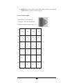
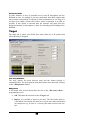
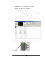
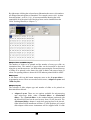
4
Chapter
MICROARRAY
Options ................................................................................................................................45
Tool group ......................................................................................................................45
Tool.................................................................................................................................45
Spots per source visit ......................................................................................................46
Wash frequency ..............................................................................................................46
Source..................................................................................................................................46
Microplate group ............................................................................................................46
Microplate type...............................................................................................................47
Number of Plates (1 BioBanks) ......................................................................................47
Number of Samples ........................................................................................................47
This run requires the x BioBank .....................................................................................47
Last Plate ........................................................................................................................47
Lid Removal ...................................................................................................................48
Source Action .................................................................................................................48
Prompt for Plates ............................................................................................................50
Target ..................................................................................................................................50
Tool array definition .......................................................................................................50
Edit pattern .....................................................................................................................50
Adaptor Plate and Slide Layout ......................................................................................52
Edit Layout .....................................................................................................................52
Adaptor Layout...............................................................................................................52
Slide Layout....................................................................................................................53
Target Action..................................................................................................................54
Pre-spotting.....................................................................................................................55
Edit pre-spotting .............................................................................................................55
Pre-spotting options ........................................................................................................55
Slide Layout....................................................................................................................57
Soft Touch ......................................................................................................................58
Edit soft touch.................................................................................................................58
Run Preferences...................................................................................................................59
General ...........................................................................................................................60
Source Action .................................................................................................................61
Target Action..................................................................................................................62
Printing ...........................................................................................................................62
Soft touch........................................................................................................................62
Climate ...........................................................................................................................62
Barcodes .........................................................................................................................64
Baths 1 & 2 .....................................................................................................................65
MWS...............................................................................................................................66
The Run ...............................................................................................................................67
Pre-Run Checks ..............................................................................................................67
Starting the Run ..............................................................................................................68
During the Run ...............................................................................................................68
43
End of Run......................................................................................................................70
44
The microarray application program allows users to produce up to 108/120
identical slides per run (see Chapter 1, page 2). The software is fully
flexible offering users the choice of where to place their arrays on the slide
and a fully customizable array design feature.
Options
The <Option> tab is where users select which pin tool configuration they
require and the frequency of washing that pin tool. It is advisable to choose the
pin tool required before working through the <Source> and <Target> tabs.
Tool group
The MicroGrid II is capable of using pins from a variety of manufacturers.
There are some 40 tool configurations for the BioRobotics MicroSpot pins
(Telechem pin tools use the same tool configurations) and 7 tool configurations
for other Majer Precision pin tools. The choice of manufacturer, whether the
pins are solid or split, and the source plate configuration (96, 384 or 1536) is
selected from this pull down menu.
Note: Only Telechem Stealth™ pins can be used on the MicroGrid II.
The tool illustration will update as tool configuration is changed, the GREEN
highlighted area being where the pins are to be placed.
Tool
The pin tool configuration is chosen in this second pull down menu.
45
Spots per source visit
This is the number of spots that the pins will attempt to deliver before they are
refilled. The number of spots that a split pin can deliver from one fill of the
reservoir is dependent on a variety of factors. These factors include temperature,
humidity, spotting solution, slide chemistry and sample concentration.
Wash frequency
The frequency of washing the pin tool is defined in this section.
•
Never wash. This option should only be used when performing test
runs, where no samples are being used.
•
Wash before pin refills. This option washes the pin before every pin
refill, even when doing repeat source visits to the same source.
•
Wash before new source visit. The pin tool is washed after every
completed source visit.
Source
The Source tab gives user definable options related to the configuration of
microplates stored in the BioBank.
Microplate group
Depending on which MicroGrid II you have dictates what options are available
from this menu. For MGII600 instruments the only option available is ‘Classic
plate definitions’ and for MGII610 instruments there are three options available;
‘Generic’, ‘Falcon’ and ‘Matrix’. Classic plate definitions are the plate types
that have been present in the software up to software version 2.1.5.0. Generic
46
plate definitions are plate definition files that require some user optimization.
The manufacturer plate definitions consist of plates that have complete
configuration files written for them. Specific manufacturer plates are listed in
the following format: catalogue number > number of well > plastic type > well
shape. Plastic types are abbreviated as: PS = polystyrene and PP =
polypropylene. Well shapes are abbreviated as: FB = flat bottom, RB = round
bottom and VB = V bottom.
Microplate type
The menu of plates listed here will depend on the <Microplate group>. The
pull down menu lists those manufacturers and plate configurations that can be
used within the MicroGrid II. It is important that you choose the plate
manufacturer and configuration that corresponds to the plate that you wish to
use.
Number of Plates (1 BioBanks)
This refers to the number of microplates stored in the BioBank, 24 plates or less
will be 1 BioBanks, 25 to 48 plates will be 2 BioBanks and so on. By entering
in the number of microplates the <Number of Samples> is automatically
calculated, assuming all the wells of the microplates contain samples.
Number of Samples
As an alternative to entering the <Number of Plates>, the number of samples
can be entered. The <Number of Plates> will be automatically updated. The
number of samples entered must be divisible by the tool type chosen under
<Options>, if not the software will adjust to the nearest appropriate value.
The software allows for the final plate of the run to be incompletely filled but
assumes that all the plates before the final plate are complete. Any gaps in the
source plates can be accounted for when the array is designed under <Target>.
The last plate must be filled as illustrated in the <Last Plate> section, the BLUE
shading corresponding to where the samples must be placed.
This run requires the x BioBank
There are three BioBank options available for use on the MicroGrid II. The
BioBank that must be used is stated in words as well as indicated by a
coloured square. The default BioBank is the standard BLACK coloured one
and is only used on MGII600 instruments. The RED BioBank only has 20
plate positions and is used for standard profile microplates. The BLUE
BioBank has 24 positions and is used for low profile microplates.
Last Plate
This section refers to the last source plate of the run. It includes an illustration of
the sample layout in the last plate, which is influenced in part by the tool type
chosen under <Options>.
To the left of the illustration is a fraction box (e.g. 24 / 24) that informs you that
the tool type selected will visit the last plate 24 times out of a possible 24 visits.
47
Each visit to a source plate by the selected tool type is termed a ‘source visit’.
Therefore, in this example 24 source visits are being made out of a possible 24
source visits.
The text in this section ‘You have a total of x source visits defined, and y distinct
tool spots available’ refers to the number of source visits set under <Source>
and the number of source visits that have been set in the array pattern under
<Target>. The x and y values should be identical. If these values match then the
text turns GREEN, if x is less than y then the text turns BLACK and if x is
greater than y then the text turns RED. When the text is RED a run cannot be
initiated.
Lid Removal
Three lid removal options are available, which have their own advantages and
disadvantages regarding speed of printing and evaporation of sample. The
instrument will check that lids have been correctly removed prior to pin tool
use. Should the lid lifter fail to pick up a lid then you will be prompted to ‘retry,
ignore or cancel’ the run, the lid can then be manually removed or the run
restarted.
•
Replace lids immediately. If this box is checked, lids are replaced
between source visits.
•
Plates have no lids. When this option is chosen the lid lifter is
deactivated and the instrument does not check for lids. If plates do have
lids and you choose this option you will cause pin tool and possible
instrument damage.
•
Remove one lid at a time. Only the lid from the source plate about to
be sampled will be removed.
•
Remove two lids at a time. Both source plate lids are removed at the
same time. Not recommended for microarraying.
Source Action
This option determines how the pin tool will behave when it is in the wells of
the microplate.
•
Wiggle. The pin tool will move left and right a user defined number of
times (see Source Action, page 61). This feature cannot be used with
split pins.
•
Dip. The pin tool will move up and down in the source plate wells a
user-defined number of times (see Source Action, page 61). It is
possible to dwell the pin tool in the microplate following a number of
dips.
48
•
Dwell. The pin tool will sit in the source plate well for a user-defined
length of time (see Source Action, page 61).
Source Visits Example:
Source plate = 96 well format
Tool type = 2x2 (96 well) split pin
12
Number of possible source visits = 24
22
23
24
17
18
19
20
13
14
15
16
9
10
11
12
5
6
7
8
1
2
3
4
49
H
G
F
E
D
C
B
A
1
2
3
4
5
6
7
8
9
10
11
21
Prompt for Plates
In some instances it may be desirable not to load all microplates into the
BioBank at once, for example if you have particularly heat labile samples that
may become compromised if exposed to room temperatures for too long or if
you have low sample volume and wish to reduce evaporation to as little as
possible. If this option is activated then the software will pause after the
designated number of microplates to allow for unloading and reloading of the
BioBank.
Target
The target tab is where users define how many slides are to be printed and
where the array is designed.
Tool array definition
The array pattern, the pitch between spots and the format selected is
summarized here. The array pattern, pitch and format can be altered by clicking
on the <Edit pattern> button.
Edit pattern
A left mouse click on this button takes the user to the <Pin array editor> –
programming screen.
•
OK. This takes the user back to the <Target> tab.
•
Import. It is possible to import a pin array. The file format must be
*.csv and the size must be the same as set in pin array editor and should
not contain text e.g. if want 10 x 10 array then must set this in the size
box.
50
•
Format. There are four format options to choose from.
Standard. Each source visit is printed at n=1.
Double offset. This option is no longer available to microarray.
Custom. Source visits can be repeated any number of times, and printed
anywhere in the array. To change a source visit number first highlight
the source visit number to be edited by clicking on it. The number can
then be changed in the ‘Edit’ box by typing the new number and
pressing the keyboard return key. The pin array screen is then updated.
A zero represents a gap in the array where no spot will be printed.
n=x. Source visits can be repeated n number of times, in this case the
replicates are laid down next to one another.
Note: The numbers displayed in the pin array editor represent source visits; the
illustration is a representation of one pin – the front left pin.
Front left pin
51
By right mouse clicking the coloured array illustration the source visit numbers
are changed into microplate well numbers. For example, source visit 1 is taken
from microplate 1 well A1 (1A1). A layout spreadsheet showing the wells
sampled for all of the pins in all of the target areas can be obtained from the
Clone Tracking Wizard (see Chapter 7).
Adaptor Plate and Slide Layout
The number of slides to be printed and the number of arrays per slide are
summarized here. The number of target slides can be increased or decreased
using the up and down arrows. An illustration representing the first and last tray
of slides to be printed is also shown, the slide in black with arrayed areas in
colour. Pre-spotting slides are shown in BLUE and non-printed slides in GREY.
Edit Layout
A left mouse click on this button transports users to the <Layout editor> –
programming screen. There are two tabs to this screen, <Adaptor Layout> and
<Slide Layout>.
Adaptor Layout
The selection of slide adaptor type and number of slides to be printed are
determined from this tab.
•
Adaptor Layout. There are two options available for microarraying
onto microscope slides, either <Vertical slides> or <Horizontal
slides>. The <Vertical slides> is the standard adaptor purchased with
the MicroGrid II and can be used to array from 1 to 48 pin tools. The
<Horizontal slides> adaptor is used when arraying from a 64 pin tool.
Older MicroGrid II instruments will have 27 slide positions per vertical
slide adaptor whilst newer instruments will be supplied with 30 slide
52
positions per vertical slide adaptor. Other adaptor options are available
if you wish to array to different substrates other than microscope slides.
•
Number of copies. Each of the four slide adaptors holds 27/30
microscope slides thus the capacity of the instrument is 108/120
microscope slides in total. The illustration to the right of the screen
represents the last tray of microscope slides and where those microscope
slides are to be positioned on that tray. The BLACK blocks represent the
number of microscope slides chosen, a GREY block represents a
microscope slide not to be printed (though the microscope slide position
must still be filled in order to maintain the integrity of the tray vacuum),
a RED block is representative of an unprintable area (a few tool types
are unable to print to the far left or right of the slide adaptors), and the
numbered coloured blocks overlying the black blocks are array areas.
Slide Layout
The positioning of the array on the microscope slide is determined in this
section.
•
Margins. All four margins of the array area can be altered
independently of one another. If the mirror margins option is enabled
then, for example as you move the left margin the right margin will
move a similar amount.
53
•
Spacing. The x and y spacing between array areas can be altered.
•
Array Area. A brightly coloured numbered block represents the array
area. The array area is dependent on the tool type chosen under
<Options>. Some tool types (e.g. 4x4 – 384 split pin) have an array
area such that up to four arrays may be printed to a single microscope
slide. These areas will be represented by different colours and be
numbered 1 to 4. So if, for example, you had 400 source visits and were
printing a standard 10x10 array then into area 1 source visits 1 to 100
would be printed, source visits 101 to 200 would be printed into area 2
and so on. The same array may be printed to a microscope slide multiple
times by changing the numbering. To do this highlight the array area to
be altered, type the new number in the ‘Sample set #’ box and press the
keyboard return key.
•
Slide size. Standard size (European and/or American) microscope slides
can be used on the slide adaptors.
•
Tool array width. The tool array width is dependent on the tool type
chosen under <Options> and can be used to calculate the number of
array areas per microscope slide and the layout of those areas on the
microscope slide.
Target Action
This section determines how the pin tool will place the sample spot onto the
sample slides.
54
•
Delay before spotting. A delay can be incorporated after the pin tool
has sampled and before it prints.
•
Target height. The distance the pin tool moves towards the slide can be
adjusted to either increase pin contact (positive value) or decrease pin
contact (negative value).
•
Dwell time. The pin tool will pause on the slide for the set time. This
may be useful where sample concentration is low, to ensure that
maximum transfer can take place. Increasing the dwell time on the slide
may increase spot size.
•
Multiple strikes. The pin tool will repeat strike each spot a given
number of times before carrying out its next operation. The option
‘Reload pins before each strike’ will become active when a value
greater than 1 is entered.
•
Delay between strikes. A time delay between multiple strikes to ensure
that the previous spot is completely dry before the next spot is laid on
top.
•
Reload pins before each strike. Depending on the number of spots per
source visit set under the <Options> tab will determine whether this
box should be checked or not.
Pre-spotting
A characteristic feature of split pins is that the first few spots tend to be larger
than subsequent spots. This is due to the ‘rush’ effect. Pre-spotting is the way to
remove this ‘rush’ before printing the sample slides. When pre-spotting is
enabled and you are only printing to one tray of slides the pre-spot slides are
shown in BLUE in the tray illustration.
Edit pre-spotting
A left mouse click on this button transports users to the <Pre-spotting
preferences> – programming screen. There are two tabs to this screen, <Prespotting Options> and <Slide Layout>.
Pre-spotting options
There are two ways of pre-spotting available the first is the historical method
that was utilized in TAS Application Suite software version 2.1.5.0 and below.
The second is the method utilized in TAS Application Suite software 2.2.0.0
and above.
55
The historical method of pre-spotting follows the pattern as described for the
sample slides. Here the pre-spotting spots are placed one on top of another
which increases the possibility of cross contamination between samples.
Therefore increased numbers of pre-spotting slides have to be used to reduce
this risk.
The new scheme for pre-spotting allows for less slides and virtually eliminates
the risk of cross contamination between samples. Here each pre-spot is
deposited onto a fresh area of the slide i.e. instead of 2 pre-spots being placed
one atop another they are placed next to one another.
•
General options. The number of pre-spots required is set here. If using
the <Historical options> then this value is equivalent to number of
slides.
•
Historical options. Pre-spotting can be done as under software version
2.1.5.0 and below to allow for backward compatibility with existing
*.grid files. However, it is recommended to upgrade to the new
methodology as less pre-spotting slides are required thus allowing for
more sample slides to be printed. The <Multiple strikes> value is the
number of times to pre-spot to each slide.
•
Pre-spotting summary. This section summaries how many pre-spot
slides are required and how many slides are then available for sample
printing. The number of pre-spotting areas required for printing the
56
sample slides is also detailed, as are the number of available pre-spotting
areas on each slide.
•
Pre-spotting protocol. The same printing parameters can either be used
for the pre-spotting slides as for the sample slides or the printing
parameters can be customized for pre-spotting. Customization may be
desirable if using two different slide chemistries for the pre-spot slides
and sample slides. There are a total of 9 parameters that can be altered
depending on whether you are pre-spotting historically or not. If you are
pre-spotting historically then only 7 out of the 9 can be altered.
Pitch. The distance between the centre of one spot and the next can be
adjusted independently of the target slide pitch. However, this value
cannot be adjusted when pre-spotting historically.
Slide layout. The number of pre-spotting areas per slide can be adjusted
independently of the sample slide layout. Cannot be adjusted when prespotting historically.
Soft touch. Soft touch slows the speed of travel of the pin tool from
100mm/s to 4mm/s. MGII610 or upgraded MGII600 instruments have
variable speed soft touch, where soft touch speed ranges from 40 – 0.6
mm/s.
Soft touch distance. The distance over which soft touch occurs.
Soft touch speed. This value is set and cannot be altered unless using
an MGII610 or upgraded MGII600 instrument.
Delay before spotting. A time delay in seconds which pauses the pin
tool before it begins printing.
Slide surface height. Slides of different substrate and manufacturer vary
in their depth, this parameter accounts for those differences.
Dwell time. A length of time in seconds that the pins remain in contact
with the slide surface.
Multiple strikes. Repeat spots can be placed one atop of another.
Delay after spotting. A time delay in seconds which pauses the pin tool
after it has printed one spot and before it prints the next thus allowing
time for the first spot to dry.
Slide Layout
The positioning and number of pre-spot areas on the pre-spotting slide is
determined in this section.
57
•
Margins. All four margins of the array area can be altered
independently of one another. If the mirror margins option is enabled
then, for example as you move the left margin the right margin will
move a similar amount.
•
Spacing. The x and y spacing between array areas can be altered.
•
Array Area. A brightly coloured numbered block represents the array
area. The array area is dependent on the tool type chosen with some tool
types (e.g. 4x4 – 384 split pin) having an array area such that up to four
arrays may be printed to a single microscope slide. These areas will be
represented by different colours and be numbered 1 to 4.
•
Pre-spotting summary. A mirror of the details on the <Pre-spotting
options> tab which updates as the number of pre-spot areas are
adjusted.
Soft Touch
Soft touch slows the speed of travel of the pin tool from 100mm/s to 4mm/s.
With some substrates and spotting solutions, spot morphology can be improved
by changing the speed at which the pin touches and leaves the slide surface.
Edit soft touch
A left mouse click on this button transports users to the <Soft Touch> tab under
<Run Preferences>. The distance over which the pin tool will travel at the
58
reduced speed is set here. The soft touch distance is calculated from various
parameters.
•
Target height. The distance the pin tool moves towards/away from
the target slides in relation to the calibration setting.
•
Soft touch distance. The distance that the pin tool will be traveling at
reduced speed before contacting the slide surface. This is calculated
independently of <Target height> and the values set here are
dependent on the thickness of the slide and any variation of the pin
lengths.
•
Speed. The pin tool will slow down from its initial velocity of
100mm/s to 4mm/s over the set distance (see above). This value is
set and cannot be altered unless using an MGII610 or upgraded
MGII600 instrument.
•
Diagram. The diagram illustrates the relation of soft touch distance
with target height. The values are representative only. The BLUE line
represents the pin, the RED line the soft touch distance and the BLACK
line is the slide.
Run Preferences
Further programming options are located under Window>Run Preferences on
the TAS Application Suite toolbar. There are 9 tabs to work through in this
section and as you complete one tab move to the next by clicking on it. Clicking
the <OK> button will take you out of <Run Preferences>.
59
General
There are a number of check boxes available under this section relating to how
the instrument will behave when a program is started.
•
Load BioBank. If this box is checked then at the start of a run the user
will be prompted to load the BioBank and conversely will be prompted
to unload the BioBank at the end of the run.
•
Load Trays. If this box is checked then at the start of a run the user will
be prompted to load the required number of trays and conversely will be
prompted to unload those trays at the end of the run. If it is unchecked
the vacuum will remain on at the end of the run.
•
Load Tool. If this box is checked then at the start of a run the user will
be prompted to load the tool and conversely at the end of a run will be
prompted to unload the tool.
•
Prime bath before start of run. If this box is checked then all three
wash stations will undergo a short priming sequence prior to the run
beginning.
•
Wash at start of run. If this box is checked then the pin tool will be
washed before the first source visit. The user can set the number of wash
cycles.
•
Wash at end of run. If this box is checked then the pin tool will be
washed after the last source visit. The user can set the number of wash
cycles.
60
•
Plug in to use. This option is unavailable at this time.
Source Action
The action of the pin tool into the source microplate wells is fine tuned in this
section.
•
Number of wiggles. The number of wiggles and wiggle deflection is set
here. The maximum deflection when using 96 well microplates is
4.5mm and 2.25mm for 384 well microplates.
•
Number of dips. The number of dips and dip deflection is set here. The
dip deflection is the distance that the pins will move back up from the
source plate before going back down for the next dip.
•
Inter-dip delay. A delay can now be introduced into the dip either at
the top or at the bottom of the dip.
•
Pin depth. The depth that the pins go into the source microplates can be
adjusted to accommodate the variation in well depth across
manufacturers. A positive value will move the pins deeper into the
wells, whilst a negative value will reduce the distance the pins move
into the wells.
Soft touch. Soft touch slows the speed of travel of the pin tool from
100mm/s to 4mm/s. MGII610 or upgraded MGII600 instruments have
variable speed soft touch, where soft touch speed ranges from 40 – 0.6
mm/s.
61
•
Dwell time. This is the waiting time that the pins spend in the source
plates. This may be useful for viscous samples.
Target Action
This section is not used for microarray.
Printing
This section is where the order of printing is determined.
•
Print first replicate on all slides first. The first replicate will be printed
onto all slides before the second replicate is printed.
•
Print all replicates on first slide first. All replicates will be printed
onto the first slide before moving onto the second slide and so on.
Soft touch
See page 58.
Climate
If a humidity control unit (HCU) has been purchased, the unit is controlled
through this section.
•
Start rate. The initial rate that humidity is added into the MicroGrid II
cabinet. The ‘start rate’ is the initial boost to get humidity to the
minimum humidity value.
•
Run rate. The rate that humidity is added into the MicroGrid II cabinet
to maintain the steady state target humidity value.
62
•
Min humid. The minimum relative humidity value that you require for
your run. It is possible to pause the run if the humidity falls below this
value by enabling the pause check box. Once the humidity increases
beyond this value the run will continue.
•
Target humid. The relative humidity value that is to be maintained
throughout the run.
•
Use humidity control. Humidity control can either be switched on or
off. Even if you do not want to use humidity control the HCU must be
switched on during a run.
•
Use only HEPA fan. There is a HEPA unit attached to the front of the
HCU, and you can choose to use the HEPA independently of the
humidifier. If using the humidifier the HEPA fan will be used
automatically.
Note: This does not control the stand-alone HEPA unit, which is only
operated by the power switch on the side of the unit.
•
Pause if humidity falls below minimum during run. If the humidity
falls below this set value then the run will be paused until the humidity
once again increases beyond this value.
•
Graph. On the graph the YELLOW line represents the actual humidity,
the RED line represents the minimum humidity value, and the GREEN
line represents the target humidity. By right mouse clicking on the graph
the frequency by which the graph updates can be altered.
63
Barcodes
Class 2 Laser Product
The barcode reader is a Class 2 laser product. Only let
professionals do the maintenance or repair. Do not
look straight into the beam, not even with optical
instruments.
The options available under this section depend on which model of barcode
scanner has been fitted to your MicroGrid II (Chapter 1, page 5).
•
Sequential option. If the microplates loaded into the BioBank have
consecutive numbering (e.g. 1, 2, 3, etc) then once you have entered the
Plate 1 barcode, and press ‘Fill’ all the other barcode cells will
automatically update.
•
Read barcodes. If you have the optional barcode scanner installed, you
can enable or disable the scanner using this check box.
•
Halt on mismatch. If, when the microplate barcodes are scanned they
do not match those barcodes entered, a warning will appear on screen
and the run will be halted.
•
Read on BB load. Upon loading the BioBank the barcodes will be
scanned in the manner selected under ‘Barcode read method’.
•
Clear cache before run. Previously cached barcodes are overwritten by
the new barcodes. Recommend that this option be always checked.
64
•
Barcode read method. (BL500) The only option available with the
BL500 barcode scanner is the third one ‘holding plates (no lids)’.
•
Barcode read method. (BL700) The BL700 barcode scanner is a more
flexible scanner utilizing a wider laser beam width. This means that
barcodes can be scanned whilst the plates are still in the BioBank and
with the plate lids on.
Baths 1 & 2
The wash parameters for the two recirculating baths are set and adjusted in this
section.
•
Use Bath 1. The user can choose not to wash in this bath if required,
however the wash bath reservoir must be filled as the bath will still
operate in recirculating mode. If enabled wash time can be adjusted,
wash times are quoted in seconds.
•
Use Bath 2. The user can choose not to wash in this bath if required,
however the wash bath reservoir must be filled as the bath will still
operate in recirculating mode. If enabled wash time can be adjusted,
wash times are quoted in seconds.
•
Wiggle. A side-to-side movement washes the pin tool. In microarray a
wiggle size of 2mm is standard.
•
Dip. An up and down movement washes the pin tool. Dip deflection can
be adjusted.
65
•
Dwell. The pin tool is washed through the recirculating action of the
wash bath.
•
Target depth for Baths 1 and 2. The depth of the pin tool in the
recirculating baths can be increased or decreased by adjusting this value.
A positive value increases the depth; a negative value decreases the
depth. The depth will have been set during installation. Adjusting this
value from zero could damage your pin tool. If you want to use Majer
Precision or Telechem pin tools then this value may require adjustment,
contact BioRobotics for advice.
•
Use recirculating baths as static baths. Baths 1 and 2 can be used as
static baths by disabling the recirculating pump, and using the supplied
polypropylene bath inserts.
MWS
The wash cycle parameters for the main wash station (MWS) are set up here.
•
Use Main Wash Station for x cycles. Checking this box enables
the main wash station and the number of wash cycles can be
adjusted.
•
Delay between cycles. If you have more than one wash cycle then
you can build in a delay between each wash cycle. It is possible to
pause the tool between each cycle using this parameter.
•
Time taken to fill MWS bath. The time taken to fill the MWS will
depend on the wash bath insert used. This value should be sufficient to
66
fill the perforated area but not too great that the water overflows and
floods the instrument. A 16 hole perforated plate typically requires 0.2
to 0.3 of a second to fill.
•
Time taken to drain MWS bath. This is the time that the MWS
vacuum will be applied for.
•
Target depth for MWS. The depth that the BioRobotics pin tool enters
the MWS will have been set during installation. Therefore, to avoid
damage to your pin tool do not adjust this value from zero. If you want
to use Majer Precision or Telechem pin tools then this value may
require adjustment, contact BioRobotics for advice.
•
Halt run if water falls below 1/3 level. A warning will be displayed on
screen when the liquid level in the 6-litre reservoir falls below the 2-litre
mark and the run will be paused.
•
Repeat entire wash cycle. The entire wash protocol (i.e. wash
behaviour in baths 1 & 2 and the MWS) can be repeated n number
of times.
The Run
The run has been programmed; you are ready to go right? Well, not quite! There
are a number of pre-run checks that need to be carried out. These checks are
carried out using the <Housekeeping> menu (Chapter 2, page 17).
Pre-Run Checks
The first thing to check is that all three wash station reservoirs have been filled
with fresh wash solutions. For the two recirculating baths disconnect all pipe
work from the two 2-litre bottles, unscrew the bottle caps, fill with fresh ultra
pure water, screw on the bottle cap making sure the rubber seal is in place, and
reconnect the pipe work. The 6-litre reservoir is drained and filled using the
<Housekeeping> toolbar buttons. The reservoir picture will indicate how full
the 6-litre reservoir is. There must always be a minimum of 2-litres in the 6-litre
reservoir.
A visual check of the four trays and the inside of the instrument should be made
to check for dust accumulation and the inside cleaned if necessary.
Before the microplates are loaded into the BioBank check that no residual
adhesive from plate sealing films has been left behind. Residual adhesive may
affect lid removal from the microplates and could thus cause damage to the pin
tool.
If you have disabled the ‘start of run’ checklist under <Run Preferences> then
you will have to load the tool, BioBank and trays using the <Housekeeping>
functions.
67
If you have the ‘start of run’ checklist enabled under <Run Preferences> then
you will be prompted to load the tool, BioBank and trays at the beginning of the
run.
Starting the Run
Finally! You have completed your pre-run checks, your source and target plates
are ready to go so all you have to do now is press the green <GO> button on the
toolbar.
The wash baths will be primed and the air pump will come on for a few
seconds, and then you will be prompted to load the tool, trays and the BioBank.
The run proper will now begin.
During the Run
Throughout the run a <Current gridding progress> window will be displayed.
This window consists of two tabs.
The <Current Progress> tab shows the start time of the run, how long the run
has taken thus far and the estimated time remaining to the end of the run. There
are four buttons displayed on this tab:
Play. Resumes the current run if been paused.
Pause. Pauses the current run. Initially only the <Pause> button
is active during a run the others being active once <Pause> has
been pressed. The same effect can be accomplished by pressing
the YELLOW button on one of the Emergency Stop boxes.
68
Spanner. Certain run parameters can be adjusted during a run.
Clicking this button transports Users to the <Mid Run
Parameters> window.
In this window certain parameters can be altered mid run. This is especially
useful when carrying out method development on the MicroGrid II. The values
that can be altered are covered elsewhere in this manual but if any changes are
made then the alterations are only used for the current run – they do not
overwrite the original run parameters.
Once any alterations have been made pressing <OK> will return the User to the
<Current gridding progress> window where the run can be resumed by
pressing the green <Play> button.
Stop. The run can be aborted by pressing this button.
The <Climate Control> tab shows the humidity throughout a run provided you
have a HCU installed otherwise this tab will be greyed out. The four sliders
allow you to adjust the climate control settings during a run.
69
End of Run
When the run has completed, the <Current gridding progress> window shuts
down and the instrument tidies itself up i.e. all axes are returned to their home
position.
If you loaded the tool, trays and BioBank through <Run Preferences> you will
be prompted to unload the tool, trays and BioBank.
If you loaded the tool, trays and BioBank through <Housekeeping> then you
will also have to use <Housekeeping> to unload these items.
Once you have unloaded everything the following message will appear to
advise you to drain the three reservoirs.
It is recommended to change the wash solutions after every print run and to
leave the reservoirs dry if the MicroGrid II will not be used for a while. This is
to prevent possible bacterial growth within the reservoirs which may lead to
contamination of your samples and damage to the instrument.
The MicroGrid II should be switched off when not in use.
70