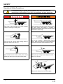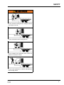
1
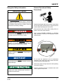
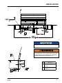
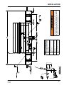
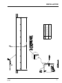
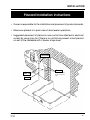
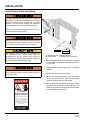
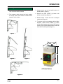
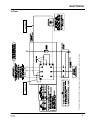
HED SERIES Hydraulic EOD Dock Leveler Owner’s/User’s Manual DLM • Division of Systems, Inc. • W194 N11481 McCormick Drive • Germantown, WI 53022 800.643.5424 • fax: 262.255.5917 • www.docksystemsinc.com • [email protected] Printed in U.S.A. Copyright © 2015 Manual No. 4111-0027 Feb 2015 July 2015 Table of Contents Page Safety Recognize Safety Information..................................................................1 General Operational Safety Precautions.................................................1 Operational Safety Precautions...............................................................2 Maintenance Safety Precautions.............................................................4 Safety Decals...........................................................................................5 Owner’s/User’s Responsibilities...............................................................6 Introduction General Information.................................................................................7 Dock Leveler Stock Specifications...........................................................7 Component Identification.........................................................................8 Installation Installations Details............................................................................... 10 Flush Mount-Weld On........................................................................... 12 Ramp Mount-Weld/Bolt On.................................................................... 14 Flush Mount-Bolt On.............................................................................. 16 Ramp Mount-Weld On w/Formed Angle................................................ 18 Formed Angle........................................................................................ 20 Ramp and Face Plate............................................................................ 22 Installation Check List............................................................................ 24 Placard Installation................................................................................. 25 Install Control Panel and Wiring............................................................. 26 Put New Dock Leveler Into Service....................................................... 27 Operation Operating Instructions............................................................................ 28 Maintenance Periodic Maintenance............................................................................ 30 Adjustments Adjust Main Pressure Relief.................................................................. 33 Adjust Lip Function................................................................................ 34 Electrical Single Phase.......................................................................................... 36 Three Phase.......................................................................................... 37 Troubleshooting Troubleshooting..................................................................................... 38 Parts HED Series............................................................................................ 40 Bumper Components............................................................................. 43 Notes Customer Information............................................................................ 45 Warranty.................................................................................. Back Cover SAFETY Recognize Safety Information Safety-Alert Symbol The Safety-Alert Symbol identifies important safety messages on equipment, safety signs, in manuals, or elsewhere. When you see this symbol, be alert to the possibility of personal injury or death. Follow the instructions in the safety message. General Operational Safety Precautions Read and understand the Owner’s/User’s manual and become thoroughly familiar with the equipment and its controls before operating the dock leveler. Never operate a dock leveler while a safety device or guard is removed or disconnected. The use of the word WARNING signifies the presence of a serious hazard or unsafe practice which may result in serious injury or death. Never remove DANGER, WARNING, or CAUTION signs, placards or decals on the equipment unless replacing them. O The use of the word DANGER signifies the presence of an extreme hazard or unsafe practice which will most likely result in severe injury or death. p ng ati er Zon e on e The use of the word CAUTION signifies possible hazard or unsafe practice which could result in personal injury. Op The use of the word NOTICE is to draw attention to a procedure that needs to be followed to prevent machine damage. g tin era Z Do not start the equipment until all unauthorized personnel in the area have been warned and have moved outside the operating zone. Remove any tools or foreign objects from the operating zone before starting. Indicates a type of safety sign, or separate panel on a safety sign, where safety-related instructions or procedures as described. Manual No. 4111-0027 Feb 2015 July 2015 Keep the operating zone free of obstacles that could cause a person to trip or fall. 1 SAFETY Operational Safety Precautions Learn the safe way to operate this equipment. Read and understand the manufacturer’s instructions. If you have any questions, ask your supervisor. Stay clear of dock leveling device when transport vehicle is entering or leaving area. Chock/restrain all transport vehicles. Never remove the wheel chocks until loading or unloading is finished and transport vehicle driver has been given permission to drive away. Do not move or use the dock leveling device if anyone is under or in front of it. Do not use a broken or damage dock leveling device. Make sure proper service and maintenance procedures have been performed before using. Keep hands and feet clear of pinch points. Avoid putting any part of your body near moving parts. Make sure lip overlaps onto transport vehicle at least 4 in. (102 mm). Keep a safe distance from both side edges. 2 Manual No. 4111-0027 Feb 2015 July 2015 SAFETY Do not use dock leveling device if transport vehicle is too high or too low. Do not overload the dock leveling device. Do not operate any equipment while under the influence of alcohol or drugs. Do not leave equipment or material unattended on dock leveling device. Manual No. 4111-0027 Feb 2015 July 2015 3 SAFETY Maintenance Safety Precautions ALWAYS disconnect electrical power source and ground wire before welding on dock leveler. DO NOT ground welding equipment to any hydraulic or electrical components of the dock leveler. Always ground to the dock leveler frame. Failure to follow these instructions may result in damage to dock leveler and/or serious personal injury or death. Hydraulic and electrical power must be OFF when servicing the equipment. For maximum protection, use an OSHA approved locking device to lock out all power sources. Only the person servicing the equipment should have the key to unlock the device. DO NOT grind or weld if hydraulic fluid or other flammable liquid is present on the surface to be ground or welded DO NOT grind or weld if uncontained hydraulic fluid or other flammable liquid is present. Stray sparks can ignite spills or leaks near the work area. Always clean up the oil leaks and spills before proceeding with grinding or welding. Always post safety warnings and barricade the work area at dock level and ground level to prevent unauthorized use of the unit before maintenance is complete. 1.50" 3.00" DANGER Always keep a fire extinguisher of the proper type nearby when grinding or welding. Failure to follow these instructions may result in serious personal injury or death. ALWAYS stand clear of dock leveler lip when working in front of the dock leveler. Failure to do this may result in serious personal injury or death. Arc Flash and Shock Hazard PPE (Personal Protection Equipment) Required De-energize equipment before working on or inside. Do not open cover without appropriate PPE. Refer to NFPA 70E for PPE requirements. This panel may contain more than one power source. Hazardous Voltage Will Cause Severe Injury or Death 4 Control Box Size: Overlay Decal Size: 1.5 x 3 File Name: 1751-0736 Manual No. 4111-0027 Feb 2015 July 2015 SAFETY Safety Decals SAFETY INFORMATION DANGER Unsupported dock leveler ramps can lower unexpectedly. 2 Before allowing vehicle to leave the dock always: Ensure that no equipment, material or people are on the dock leveler. Return the dock leveler to its stored position at dock level. Failure to follow posted instructions will result in death or serious injury. Unsupported dock leveler ramps can lower unexpectedly. Before allowing vehicle to leave the dock always: Ensure that no equipment, material or people are on the dock leveler. Return the dock leveler to its stored position at dock level. Failure to follow posted instructions will result in death or serious injury. Maintenance/Service 1. Read and follow all instructions, warnings and maintenance schedules in the owner’s/user’s manual. 2. Maintenance/Service of dock leveler restricted to trained personnel. 3. Place barriers on the driveway and on dock floor to indicate service work is being performed. 4. DO NOT ENTER PIT unless dock leveler is securely supported by maintenance prop. 5. If electrically powered turn off and use OSHA lockout/tagout procedures. Call 262.255.1510 for replacement placards, warning labels, or owner’s/user’s manuals. Operation 1. Read and follow all instructions and warnings in the owner’s/user’s manual. 2. Use of dock leveler restricted to trained operators 3. Always chock trailer wheels or engage truck restraint before operating dock leveler or beginning to load or unload. 4. Never use hands or equipment to move the ramp or lip 5. Before activating dock leveler: Ensure trailer is backed in against bumpers. Remove any end loads if required. Check trailer alignment to avoid lip interference. If lip does not lower to trailer bed, reposition vehicle. 6. Ensure that truck bed supports extended lip or the leveler frame Supports the ramp before driving on ramp. 7. Stay clear of hinges and front and sides of moving dock leveler. 8. Never use damaged or malfunctioning dock leveler. Report problems immediately to supervisor. Maintenance/Service 1. Read and follow all instructions, warnings and maintenance schedules in the owner’s/user’s manual. 2. Maintenance/Service of dock leveler restricted to trained personnel. 3. Place barriers on the driveway and on dock floor to indicate service work is being performed. 4. DO NOT ENTER PIT unless dock leveler is securely supported by maintenance prop. 5. If electrically powered turn off and use OSHA lockout/tagout procedures. Call 262.255.1510 for replacement placards, warning labels, or owner’s/user’s manuals. ! DANGER ! DANGER 3 Supports the ramp before driving on ramp. 7. Stay clear of hinges and front and sides of moving dock leveler. 8. Never use damaged or malfunctioning dock leveler. Report problems immediately to supervisor. SAFETY INFORMATION DANGER 2 Operation 1. Read and follow all instructions and warnings in the owner’s/user’s manual. 2. Use of dock leveler restricted to trained operators 3. Always chock trailer wheels or engage truck restraint before operating dock leveler or beginning to load or unload. 4. Never use hands or equipment to move the ramp or lip 5. Before activating dock leveler: Ensure trailer is backed in against bumpers. Remove any end loads if required. Check trailer alignment to avoid lip interference. If lip does not lower to trailer bed, reposition vehicle. 6. Ensure that truck bed supports extended lip or the leveler frame CRUSH HAZARD DO NOT REMOVE hydraulic cylinder until leveler is safely supported by maintenance prop. Refer to owner’s/user’s manual for proper maintenance procedure. Failure to comply will result in death or serious injury. 1 2 Ramp swings toward you. Stand Clear. Use maintenance strut while servicing. Failure to do so will result in death or serious injury. 1 4 3 2 Manual No. 4111-0027 Feb 2015 July 2015 Decal 2 will have two positions, one on the outside of the left bumper and one on the outside of the right bumper. Decal 4 represents the placement of the serial tag. 5 OWNER’S/USER’S RESPONSIBILITIES 1. The owner/ user should recognize the inherent dangers of the interface between the loading dock and the transportation vehicle. The owner/ user should, therefore, train and instruct all operators in the safe operation and use of the loading dock equipment in accordance with manufacturer’s recommendations and industry standards. Effective operator training should also focus on the owner’s/user’s company policies and operating conditions. Maintaining, updating and re training all operators on safe working habits and operation of the equipment, regardless of previous experience, should be done on a regular basis and should include an understanding and familiarity with all functions of the equipment. Owner’s/ user’s shall actively maintain, update and retrain all operators on safe working habits and operations of the equipment. 2. The manufacturer shall provide to the initial purchaser all necessary information regarding Safety Information, Operation, Installation and Safety Precautions, Recommended Initial and Periodic Inspections Procedures, Planned Maintenance Schedule, Product Specifications, Troubleshooting Guide, Parts Break Down, Warranty Information, and Manufacturers Contact Information, as well as tables to identify the grade(slope) for all variations of length or configuration of the dock leveling device and information identifying the maximum uncontrolled drop encountered when sudden removal of support while in the working range of the equipment. 3. It is recommended that when the transportation vehicle is positioned correctly in the dock opening and in contact with both bumpers, there shall be a minimum of 4.00 inches (100mm) overlap of the leveling device and the transportation vehicle at all times during the loading and unloading process. 4. The Owner/User must review all name plates, placards, decals, instructions and posted warnings and place the same in view of the operator or maintenance personnel for whom such warnings are intended for. Contact manufacturer for any replacements. 5. Manufacturer’s recommended periodic maintenance and inspection procedures in effect at the date of shipment shall be followed at all times. Written documentation of maintenance, replacement parts or damage should be retained. In the event of damage notification to the manufacturer is required. 6. Loading dock equipment that has been structurally damaged or has experienced a sudden loss of main support while under load (such as what might occur when a transport vehicle pulls out from under the leveling device) shall be removed from service, inspected by a manufacturer’s authorized representative, and repaired or replaced as needed before being placed back in service. 7. Any modifications or alterations of loading dock equipment shall only be done with prior written approval from the manufacturer and the same shall be at least as safe as the original equipment was prior to the modification and shall also satisfy all safety requirements of the manufacturer for the particular application of the leveling device. 8. When industrial moving devices are being used in the loading or unloading of product from the transportation vehicle, this vehicle shall have the brakes and wheel chocks applied appropriately or all other positive restraining device shall be fully utilized. It is recommended that transport vehicles with airride suspension systems shall have its air exhausted prior to performing loading and unloading operation to minimize transport vehicle bed drop. 9. Loading dock safety equipment should never be used outside of its intended use, vertical working range, or capacity. Please consult the manufacturer if you have any questions as to the use, vertical working range or capacity of the equipment. Only properly trained and authorized personnel should operate the equipment. 10.When selecting loading dock safety equipment, it is important to consider not only present requirements but also future plans and any possible adverse conditions, environmental factors or usage. 6 Manual No. 4111-0027 Feb 2015 July 2015 INTRODUCTION General Information Congratulations on your choice of a DLM Edge-ofDock leveler. This manual covers the HED series mechanical Edge-of-Dock levelers. Designed by DLM to be a marvel of simplicity and efficiency, your dock leveler, when properly installed, will provide many years of trouble-free performance with an absolute minimum of maintenance. To obtain maximum performance and longest possible use, a simple program of preventive maintenance is recommended. Once again, thank you and congratulations on your purchase of a DLM Hydraulic Edge-of-Dock leveler. The HED series Edge-of-Dock leveler comes equipped with an electrical control panel, which allows pushbutton operation of the dock leveler functions. Each HED dock leveler unit and control panel has been factory pre-wired and tested to ensure satisfactory operation. HED Series Edge-of-Dock levelers are available in the following sizes, weight capacities, and options: Dimensions and Capacities Model # - Deck - Width Total Unit Width Comparative Industry Rating HED-6666” 104” 20,000 HED-7272” 110” 25,000 HED-7878” 116” 30,000 35,000 HED-8484” 122” Call Systems Inc to discuss available voltages, phases and options to meet your specific needs. To illustrate which connections are to be made in the field at installation, electrical drawings are included with each order or by contacting Systems, Inc. Technical Services. Once again, thank you and congratulations on your purchase of a DLM Hydraulic Edge-of-Dock leveler. Manual No. 4111-0027 Feb 2015 July 2015 7 INTRODUCTION Component Identification A F B E D C G J H A — Lip Plate B —Center Plate C — Safety Prop D — Powerpack (Motor/Pump/Reservoir) E — Hinge Area F — Lip Cylinder G — Main Hoist Cylinder H — Bumper Blocks (2 used) J —Raise Button THEORY The HED Edge-of-Dock leveler uses hydraulic pressure and single push-button operation for ease of use. Platform (B) is raised by depressing and holding the RAISE button (J). This activates an electric motor (D) which, in turn, drives a hydraulic pump. The hydraulic pump forces oil into the platform cylinder (G), causing the platform to rise. Hold (J) until lip fully extends. 8 Releasing the raise button will allow the platform to float down to the bed of the transport vehicle. The lip will stay extended until the platform reaches the full below dock position. Depressing the raise button will return the platform and lip to the stored position. Manual No. 4111-0027 Feb 2015 July 2015 INTRODUCTION This page intentionally left blank Manual No. 4111-0027 Feb 2015 July 2015 9 INSTALLATION INSTALLATION DETAILS Post safety warnings and barricade the work area at dock level and ground level to prevent unauthorized use of the dock leveler before installation has been completed. Failure to follow the installation instructions can result in damage to dock leveler, the facilities, and/ or serious personal injury or death. Only trained installation professionals with the proper equipment should install this product. DO NOT grind or weld if hydraulic fluid or other flammable liquid is present on the surface to be ground or welded. DO NOT grind or weld if uncontained hydraulic fluid or other flammable liquid is present. Stray sparks can ignite spills or leaks near the work area. Always clean up the oil leaks and spills before proceeding with grinding or welding. Always keep a fire extinguisher of the proper type nearby when grinding or welding. Failure to follow these instructions may result in serious personal injury or death. DO NOT remove the shipping bands around the dock leveler lip until instructed to do so. 10 Manual No. 4111-0027 Feb 2015 July 2015 INSTALLATION IMPORTANT DO NOT connect the dock leveler electrical wiring and ground connections until all welding has been completed. DO NOT ground welding equipment to any hydraulic or electrical components of the dock leveler. Always ground welding equipment to the dock leveler frame, NEVER to the platform. Failure to follow these instructions may damage the motor, hoist cylinder, wiring, and/or control panel. If the platform is raised using an external lifting device or the hydraulic system is opened to atmosphere, air will enter into the hydraulic system. Whenever this happens, always cycle the leveler at least 4 times using the leveler’s own hydraulic power system before allowing the leveler to be put into service. This is to make sure all air is purged from the hydraulic cylinders. Failure to do this may result in serious personal injury or death. Two people are required to engage the maintenance prop: one person to operate the lifting device, the other person to engage the maintenance prop. Manual No. 4111-0027 Feb 2015 July 2015 11 INSTALLATION H.E.D. Installation Instructions - Flush Mount - Weld On Follow all safety precautions prior to installation. A flush mount weld on application is used when an 8” wide (minimum) embed channel is securely anchored into the concrete at the dock edge, and the dock height is adequate. Installation Steps: 1. Remove all existing bumper material and protruding objects from dock edge. Clean and sweep dock edge free of debris and flammable chemicals before installing unit. 2. At chosen location for Edge-of-Dock leveler, locate the center of space and mark a point half of the base plate width to the left and right. 3. Using a proper lifting device, raise and position leveler on dock face with the top of the base plate being flush with the top of the embedded channel. Position ends of base plate to match up with marks made previously. 4. Tack weld base plate to dock steel on left hand end of the leveler. Check right hand end of base plate, ensure that end is against dock steel and that the top of the base plate is still flush with the top of the embedded channel. Tack right hand end to dock steel. 8. Installer must remove all welding slag, and repaint welded areas. 9. Drill 5/8” dia. by 5” deep holes in concrete through holes in lower cylinder mount, and install anchor bolts with washers and tighten securely. 10. Field mount control box to inside wall. Field wire control box and hydraulic power unit per electrical schematic(s) provided. Read and comply with all local electrical codes. 11. Before install is complete, installer must make a final operational check of dock leveler to verify all phases of install are correct. Installer must complete, sign and return the Installation Checklist upon completion. Reference page 24. Motor should NOT be wired in while welding. 5. Position bump blocks out approximately 5/8” from the edge of the inside flange of the bump block to the end of the base plate. This will allow for vertical welding of both the base plate and the bump block flange back to the dock steel. Top of the bump block cover plate should be flush with the top of the embed channel. Tack weld bump blocks to dock steel. 6. Check the positioning of the base plate and the bump blocks. 7. Complete welding of tacked parts as follows: A.Apply a continuous weld across top of each bumper and base plate to dock steel. Skip welding is acceptable to prevent warping,completed. B. Weld vertically along each end of base plate and on both inboard and outboard flanges of bump blocks. C. Fully plug weld all holes in base plate. 12 Manual No. 4111-0027 Feb 2015 July 2015 Manual No. 4111-0027 Feb 2015 July 2015 DESCRIPTION Top of base plate and bumper cover plate to be flush with top of dock floor and embedded channel Apply continuous bevel weld across both bumpers and length of base plate. NOTE 1 2 Junction Box Securely block or support ramp and lip when in vertical positions. Lack of proper bracing can result in ramp dropping during adjustment or installation causing personal injury or damage to unit. INSTALLATION 13 INSTALLATION H.E.D. Installation Instructions - RampMount - Weld/Bolt On Follow all safety precautions prior to installation. A ramp mount-weld on application is used when adequate dock steel is securely anchored in the concrete at the dock edge, but the existing dock height is too low and the dock leveler must be installed above this height to correct this situation. Installation Steps: 1. Remove all existing bumper material and protruding objects from dock edge. Clean and sweep dock edge free of debris and flammable chemicals before installing unit. 2. At chosen location for Edge of Dock leveler, locate the center of space and mark a point half of the base plate width to the left and right. 3. At the points marked to each side of center, measure and mark points 7-3/4” below dock level less height the unit is to be raised to locate bottom of base plate. This will locate the top of the base plate X” above dock level. 4. Using a proper lifting device, raise and position the leveler base plate to marked position. While holding base plate tight against dock face, tack weld securely to dock steel on left hand end of leveler. Check right hand end of base plate, ensure that end is against dock steel and that the bottom of the base plate is even with the marks made previously. Tack right hand end to dock steel. Support unit until final welding is ready to complete. 5. Position bump blocks out approximately 5/8” out from the edge of the inside flange of the bump block to the end of the base plate. Position the top of the tread cover plate on the bump blocks to be flush with the top of the base plate. Tack weld bump blocks to dock steel. 6. Place steel ramp plate in position, flush with top backside of base plate. Mark along full length of back edge of ramp plate. Slide ramp plate forward over dock leveler the width of bushing tool, approximately 2”. 7. Place bushing tool on marked line at each end of ramp to ensure proper alignment at both ends, and tack weld ramp plate to dock leveler to hold ramp plate in place while bushing. A Skil Roto Hammer #736 or similar tool is recommended. 14 8. Using the back edge of the ramp plate as a guide, groove concrete approximately 3/4” deep by 2” wide, and should be the entire length of ramp plate. 9. Break tack welds holding ramp in place, slide ramp plate back into position with the top of the ramp plate flush with the top of the base plate. Tack weld each end and center of ramp plate to base plate. 10. Drill 5/8” dia. by 5” deep holes through ramp plate at back edge. Install anchor bolts per manufacturers specifications, and tighten securely. Weld anchor bolt nuts to ramp plate using a ¼” fillet weld all the way around the nut. Cut off any portion of the anchor bolt exposed through the nut, and plug weld around the top of the nut to the anchor bolt. Ensure the top of the nuts are well rounded for smooth rollover. 11. Complete welding of tacked parts as follows: A. Apply continuous weld across top of each bumper and base plate to ramp plate. Skip welding is acceptable to prevent warping, but complete weld must be completed. B. Weld vertically along each end of base plate and on both inboard and outboard flanges of bump blocks. C. Fully plug weld all holes in base plate. 12. Installer must remove all welding slag, and repaint welded areas. 13. Drill 5/8” dia. by 5” deep holes in concrete through holes in lower cylinder mount, and install anchor bolts with washers and tighten securely. 14. Field mount control box to inside wall. Field wire control box and hydraulic power unit per electrical schematic(s) provided. Read and comply with all local electrical codes. 15. Before install is complete, installer must make a final operational check of dock leveler to verify all phases of install are correct. Installer must complete, sign, and return the Installation Checklist upon completion. Reference page 24. Motor should NOT be wired in while welding. Manual No. 4111-0027 Feb 2015 July 2015 Manual No. 4111-0027 Feb 2015 July 2015 DESCRIPTION Top of base plate and bumper cover plate to be flush with top of ramp plate. Apply continuous bevel weld across both bumpers and length of base plate. To figure ramp plate length, need 12” ramp for every 1-1/2” of rise to ramp. NOTE 1 2 3 Junction Box Securely block or support ramp and lip when in vertical positions. Lack of proper bracing can result in ramp dropping during adjustment or installation causing personal injury or damage to unit. INSTALLATION 15 INSTALLATION H.E.D. Installation Instructions - Flush Mount - Bolt On Follow all safety precautions prior to installation. A flush mount bolt on application is used when there is no steel on dock edge, and the dock height is adequate. Additional steel ramp plate and bolting is required with this type of installation. Installation Steps: 1. Remove all existing bumper material and protruding objects from dock edge. Clean and sweep dock edge free of debris and flammable chemicals before installing unit. 2. At chosen location for Edge of Dock leveler, locate the center of space and mark a point half of the base plate width to the left and right. 3. At the points marked to each side of center, measure and mark points 7-1/2” below dock level (for ¼” ramp plate) to locate position for bottom of base plate. This position will place the top of the base plate ¼” above the dock floor. This position will vary with ramp plate thickness. 4. Mark line connecting these points and position support angles. Position angles as shown in installation drawing provided. Mark center of holes in each of the support angles. 5. At center marks, drill holes 5/8” dia. by 5” deep in concrete. Install anchor bolts with washers through support angles into holes in concrete. Tighten bolts until support angles are secure. Follow anchor manufacturers installation instructions for proper installation. 6. Using a proper lifting device, raise and position the leveler base plate to marked position, while resting on the support angles. While holding base plate tight against dock face, tack weld securely to support angles. 7. Drill 5/8” dia. by 5” deep holes in concrete through holes in base plate, and install anchor bolts with washers and tighten securely. 8. Position bump blocks out approximately 5/8” out from the edge of the inside flange of the bump block to the end of the base plate. Position the top of the tread cover plate on the bump blocks to be ¼” above dock level. Note that this placement will vary with ramp plate thickness. Mark centers of holes in bump block flanges. 9. Drill 5/8” dia. by 5” deep holes at center marks. Reposition bump blocks, insert anchor bolts with washers and tighten securely to dock face. 10. Place steel ramp plate in position, flush with top 16 backside of base plate. Mark along full length of back edge of ramp plate. Slide ramp plate forward over dock leveler the width of bushing tool, approximately 2”. 11. Place bushing tool on marked line at each end of ramp to ensure proper alignment at both ends, and tack weld ramp plate to dock leveler to hold ramp plate in place while bushing. A Skil Roto Hammer #736 or similar tool is recommended. 12. Using the back edge of the ramp plate as a guide, groove concrete approximately 5/8” deep by 2” wide, and should be the entire length of ramp plate. 13. Break tack welds holding ramp in place, slide ramp plate back into position with the top of the ramp plate flush with the top of the base plate. Tack weld each end and center of ramp plate to base plate. 14. Drill 5/8” dia. by 5” deep holes through ramp plate at back edge. Install anchor bolts per manufacturers specifications, and tighten securely. Weld anchor bolt nuts to ramp plate using a ¼” fillet weld all the way around the nut. Cut off any portion of the anchor bolt exposed through the nut, and plug weld around the top of the nut to the anchor bolt. Ensure the top of the nuts are well rounded for smooth rollover. 15. Complete welding of tacked parts as follows: A. Apply continuous weld across top of each bumper and base plate to ramp plate. Skip welding is acceptable to prevent warping, but complete weld must be completed. B. Weld bottom of base plate to support angles using a ¼” fillet weld. 16. Installer must remove all welding slag, and repaint welded areas. 17. Drill 5/8” dia. by 5” deep holes in concrete through holes in lower cylinder mount, and install anchor bolts with washers and tighten securely. 18. Field mount control box to inside wall. Field wire control box and hydraulic power unit per electrical schematic(s) provided. Read and comply with all local electrical codes. 19. Before install is complete, installer must make a final operational check of dock leveler to verify all phases of install are correct. Installer must complete, sign, and return the Installation Checklist upon completion. Reference page 24. Manual No. 4111-0027 Feb 2015 July 2015 INSTALLATION Junction Box Motor should NOT be wired in while welding. Securely block or support ramp and lip when in vertical positions. Lack of proper bracing can result in ramp dropping during adjustment or installation causing personal injury or damage to unit. Manual No. 4111-0027 Feb 2015 July 2015 NOTE DESCRIPTION 1 Top of base plate and bumper cover plate to be flush with top of ramp plate. 2 Apply continuous bevel weld across both bumpers and length of base plate. 17 INSTALLATION H.E.D. Installation Instructions - Ramp Mount - Weld On w/Formed Angle Follow all safety precautions prior to installation. A ramp mount-weld on used with a formed angle application is used when dock edge is damaged, there is no dock steel securely anchored into the concrete, and the dock height is too low and the leveler must be installed above this height to correct this situation. Installation Steps: 1. Remove all existing bumper material and protruding objects from dock edge. Clean and sweep dock edge free of debris and flammable chemicals before installing unit. 2. Review and follow formed angle installation instructions prior to leveler installation. 3. At chosen location for Edge of Dock leveler, locate the center of space and mark a point half of the base plate width to the left and right. 4. At the points marked to each side of center, measure and mark points 7-3/4” below dock level less height the unit is to be raised to locate bottom of base plate. This will locate the top of the base plate X” above dock level. 5. Using a proper lifting device, raise and position the leveler base plate to marked position. While holding base plate tight against dock face, tack weld securely to dock steel on left hand end of leveler. Check right hand end of base plate, ensure that end is against dock steel and that the bottom of the base plate is even with the marks made previously. Tack right hand end to dock steel. Support unit until final welding is ready to complete. 6. Position bump blocks out approximately 5/8” out from the edge of the inside flange of the bump block to the end of the base plate. Position the top of the tread cover plate on the bump blocks to be flush with the top of the base plate. Tack weld bump blocks to dock steel. 7. Place steel ramp plate in position, flush with top backside of base plate. Mark along full length of back edge of ramp plate. Slide ramp plate forward over dock leveler the width of bushing tool, approximately 2”. 8. Place bushing tool on marked line at each end of ramp to ensure proper alignment at both ends, and tack weld ramp plate to dock leveler to hold ramp plate in place while bushing. A Skil Roto Hammer #736 or similar tool is recommended. 18 9. Using the back edge of the ramp plate as a guide, groove concrete approximately 3/4” deep by 2” wide, and should be the entire length of ramp plate. 10. Break tack welds holding ramp in place, slide ramp plate back into position with the top of the ramp plate flush with the top of the base plate. Tack weld each end and center of ramp plate to base plate. 11. Drill 5/8” dia. by 5” deep holes through ramp plate at back edge. Install anchor bolts per manufacturers specifications, and tighten securely. Weld anchor bolt nuts to ramp plate using a ¼” fillet weld all the way around the nut. Cut off any portion of the anchor bolt exposed through the nut, and plug weld around the top of the nut to the anchor bolt. Ensure the top of the nuts are well rounded for smooth rollover. 12. Complete welding of tacked parts as follows: A. Apply continuous weld across top of each bumper and base plate to ramp plate. Skip welding is acceptable to prevent warping, but complete weld must be completed. B. Weld vertically along each end of base plate and on both inboard and outboard flanges of bump blocks. C. Fully plug weld all holes in base plate. 13. Installer must remove all welding slag, and repaint welded areas. 14. Drill 5/8” dia. by 5” deep holes in concrete through holes in lower cylinder mount, and install anchor bolts with washers and tighten securely. 15. Field mount control box to inside wall. Field wire control box and hydraulic power unit per electrical schematic(s) provided. Read and comply with all local electrical codes. 16. Before install is complete, installer must make a final operational check of dock leveler to verify all phases of install are correct. Installer must complete, sign, and return the Installation Checklist upon completion. Reference page 24. Motor should NOT be wired in while welding. Manual No. 4111-0027 Feb 2015 July 2015 Manual No. 4111-0027 Feb 2015 July 2015 DESCRIPTION Top of base plate and bumper cover plate to be flush with top of ramp plate. Apply continuous bevel weld across both bumpers and length of base plate. To figure ramp plate length, need 12” ramp for every 1-1/2” of rise to ramp. To install formed angle, see formed angle installation instructions. NOTE 1 2 3 4 Junction Box Securely block or support ramp and lip when in vertical positions. Lack of proper bracing can result in ramp dropping during adjustment or installation causing personal injury or damage to unit. INSTALLATION 19 INSTALLATION H.E.D. Installation Instructions - Formed Angle Follow all safety precautions prior to installation. A formed angle is used when there is no existing dock steel and concrete at the dock edge has been damaged. The formed angle is required to rebuild the damaged concrete edge for a proper installation if the dock height is adequate. Installation Steps: 1. Remove all existing bumper material and protruding objects from dock edge. Clean and sweep dock edge free of debris and flammable chemicals before installing unit. 2. At chosen location for the formed angle, locate the center of space and mark a point half of the angle width to the left and right. 3. Using a proper lifting device, raise and position the formed angle to marked position, slide formed angle against dock face. 4. Mark along full length of back edge of formed angle. Slide angle forward the width of brushing tool, approximately 2”. 5. Place brushing tool on marked line at each end of formed angle to ensure proper alignment at both ends. A Skil Roto Hammer #736 or similar tool is recommended. 6. Using the back edge of the formed angle as a guide, groove concrete approximately 5/8” deep by 2” wide, and should be the entire length of the formed angle. 7. Slide formed angle back until tight against dock face. drill 5/8” dia. by 5” deep holes through formed angle at back edge. Install anchor bolts per manufacturers specifications, and tighten securely. Weld anchor bolt nuts to formed angle using a 1/4” fillet weld all the way around the nut. Cut off any portion of the anchor bolt exposed through the nut, and plug weld around the top of the nut to the anchor bolt. Ensure the top of the nuts are well rounded for smooth rollover. 8. Drill 5/8” dia. by 5” deep holes in dock face through holes in formed angle. Install anchor bolts with washers and tighten securely per manufacturers specifications. 20 Manual No. 4111-0027 Feb 2015 July 2015 Manual No. 4111-0027 Feb 2015 July 2015 1 NOTE Secure formed angle with (18) anchor bolts, (9) each side DESCRIPTION INSTALLATION 21 INSTALLATION H.E.D. Installation Instructions - Ramp and Face Plate Follow all safety precautions prior to installation. A ramp mount requiring a face plate application is used when there is no existing dock steel and the concrete at the dock edge has been damaged. The dock height can be low, high, or adequate for this application, however, the face plate and ramp plate are required to rebuild the damaged concrete edge. securely. Weld anchor bolt nuts to ramp plate using a 1/4” fillet weld all the way around the nut. Cut off any portion of the anchor bolt exposed through he nut, and plug weld around the top of the nut to the anchor bolt. Ensure the top of the nuts are well rounded for smooth rollover. Installation Steps: 1. Remove all existing bumper material and protruding objects from dock edge. Clean and sweep dock edge free of debris and flammable chemicals before installing unit. 11. Apply a continuous fillet weld at the created joint between the face plate and ramp. Skip welding should be the proper method used to avoid warping, and a complete weld must be achieved. 2. At chosen location for the face plate, locate the center of space and mark a point half of the face plate width to the left and right. 3. Using a proper lifting device, raise and position the face plate to marked position, and push face plate against dock face. 4. Top of face plate should be flush with the top of dock floor. Mark center of holes in face plate into dock face. Drill 5/8” dia. by 5” holes into dock face. Install anchor bolts with washers per manufacturers specifications and tighten securely. 5. Place ramp plate to match each end of the face plate. Leading (forward) edge of ramp plate should be flush with dock face. 6. Mark along full length of back edge of ramp plate. Slide ramp forward the width of bushing tool, approximately 2”. 7. Place bushing tool on marked line at each end of ramp to ensure proper alignment at both ends. A Skil Roto Hammer #736 or similar tool is recommended. 8. Tack weld ramp to face plate on each end to secure in place. 9. Using the back edge of the ramp plate as a guide, groove concrete approximately 5/8” deep by 2” wide, and should be the entire length of the lamp plate. 10. Break tack welds and slide ramp back until forward edge is flush with dock face. Tack weld ramp on each end and center to face plate. Drill 5/8” dia. by 5” deep holes through ramp plate at back edge. Install anchor bolts per manufacturers specifications, and tighten 22 Manual No. 4111-0027 Feb 2015 July 2015 Manual No. 4111-0027 Feb 2015 July 2015 Secure formed angle with (18) anchor bolts, (9) each side Apply continuous fillet weld across entire length of face plate and ramp 2 DESCRIPTION 1 NOTE INSTALLATION 23 INSTALLATION CHECK LIST E.O.D. Installation Checklist Date: __________ Order No.: __________ Serial Number:______________ Installer: ____________________________ Customer Name: _____________________ Address: ____________________________ City/State: ___________________________ Zip: __________ Phone: _________________ 1. Unit is properly aligned and installed properly. 2. All welding has been fully completed. 3. Welding slag has been removed. 4. Welds and other affected areas have been painted. 5. Springs have been properly adjusted. 6. Unit is functioning properly without fault. I hereby certify that all installation and/or repair work has been inspected and approved by: Company: ________________________ Date Completed: _________________ Name: ___________________________ Signature: ______________________ A copy of this document must be signed and faxed to Systems, Inc at 262-257-7399 to the attention Customer Service/ Technical Service. To be placed in job folder. Copy as needed 24 Manual No. 4111-0027 Feb 2015 July 2015 INSTALLATION Placard Installation Instructions • Owner is responsible for the installation and placement of product placards. • Make sure placard is in plain view of dock leveler operations. • Suggested placement of placard is near control box attached to electrical conduit by using nylon tie. If there is no control box present, mount placard on wall to the immediate left of leveler at eye level. Control Box Placard Nylon Tie (Placard placement shown as reference only.) Conduit Manual No. 4111-0027 Feb 2015 July 2015 25 INSTALLATION Install Control Panel and Wiring The electrical power must be OFF prior to electrical installation. For maximum protection, use an OSHA approved locking device to lock out all power sources. Only the person installing the equipment should have the key to unlock the power source. Failure to follow these instructions may result in serious personal injury or death. DO NOT make any final electrical connections until all welding has been completed. Failure to do this may result in serious personal injury or death. A B C e Lin ter L) n Ce (C 32” off CL All electrical work — including the installation of the disconnect panel, control panel, and final connections to the pit junction box — must be performed by a certified electrician and conform to all local and applicable national codes. Always stand clear of platform lip when working in front of the dock leveler. Serious personal injury or death may result. 1.50" 3.00" DANGER Arc Flash and Shock Hazard PPE (Personal Protection Equipment) Required 16” DOWN A— Disconnect Panel (provided by others) B— Control Panel C— Distance, 48 in. (14 630 mm) 1. Mount the push-button control panel (B) so bottom of control panel-to-dock floor distance (C) is 48 in. (1219.2 mm). 2. Install electrical disconnect panel (A) if not already installed. 3. Install and connect the control wiring. 4. Connect the dock leveler power cable to the field wires in the pit junction box. Refer to the electrical drawings supplied with the dock leveler. 5. After all electrical connections have been made, disengage the maintenance prop and lower the platform using the external lifting device connected to the platform lifting brackets. De-energize equipment before working on or inside. Do not open cover without appropriate PPE. Refer to NFPA 70E for PPE requirements. This panel may contain more than one power source. Hazardous Voltage Will Cause Severe Injury or Death 26 Control Box Size: Overlay Decal Size: 1.5 x 3 File Name: 1751-0736 Manual No. 4111-0027 Feb 2015 July 2015 INSTALLATION Put New Dock Leveler Into Service 1. Disconnect the external lifting device 2. Install the dock bumpers as required. 3. Turn the main electrical power ON. 4. Raise the leveler platform fully by depressing and holding the RAISE button. NOTE:The platform of a properly operating dock leveler will automatically stop rising when it reaches its full raised height, at which point, the lip extends. 5. Release the RAISE button to lower the platform. As long as there is no transport vehicle present at the dock, the platform will lower to the full below-dock position as the lip folds. NOTE: If a transport vehicle is present, the platform will lower until the lip rests on the transport vehicle bed. (See Operating Instructions in Operation section.) 6. Perform steps 4 & 5 at least four times to purge any air that may be in the hydraulic system and to ensure proper operation. Always stand clear of platform lip when working in front of the dock leveler. Serious personal injury or death may result. Unless the dock leveler is equipped with a tethered remote, two people are required to engage the maintenance prop: one person to operate the unit, the other person to engage the maintenance prop. Manual No. 4111-0027 Feb 2015 July 2015 27 OPERATION Operating Instructions Stay clear of dock leveler when transport vehicle is entering or leaving dock area. 5 in. (127 mm) DO NOT move or use the dock leveler if anyone is under or in front of leveler. Keep hands and feet clear of pinch points. Avoid putting any part of your body near moving parts. Failure to follow these instructions will result in severe personal injury or death. Only trained personnel should operate the dock leveler. DO NOT use a broken or damaged dock leveler. Make sure proper service and maintenance procedures have been performed on leveler before using. Transport vehicle wheels must be chocked unless the vehicle restraint is used. Never remove the wheel chocks until loading/unloading is finished and transport vehicle driver has been given permission to leave. 5 in. (127 mm) The HED hydraulic Edge-of dock leveler is designed to compensate for a maximum ± 5 in.* (127 mm) of height difference between the loading dock and the transport vehicle bed. DO NOT use the dock leveler if the transport vehicle bed is more than 5 in. (127 mm) higher or lower than the dock floor. *Service height may vary with design specifications DO NOT overload the dock leveler. DO NOT operate any equipment while under the influence of alcohol or drugs. DO NOT leave equipment or material unattended on the dock leveler. Failure to follow these instructions may result in personal injury and/or damage to equipment. Make sure platform lip rests on the transport vehicle bed with at least 4 in. (102 mm) of overlap. Maintain a safe distance from side edges of leveler during the loading/unloading process. Failure to follow these instructions may result in serious personal injury or death. 28 Manual No. 4111-0027 Feb 2015 July 2015 OPERATION Operating Instructions 1. Make certain all equipment and personnel are clear of leveler before operation. 3. Always remove any end load while leveler is in stored position. (Figure 1). 2. The transport vehicle should be firmly against the bump blocks and wheels chocked before operation of the leveler. 4. Depress and hold “RAISE” (A) button until leveler extends fully (Figure 3). 5. Release button. Leveler will lower to transport vehicle bed (Figure 4). 6. To remove leveler from transport vehicle before departure, operate leveler “RAISE” (A) button until lip clears transport vehicle bed, folds up and returns, (Figure 2) then release button. Leveler will then return to stored position (Figure 1). Figure 1 3.50 0 4.5 6.50 Figure 3 Figure 2 A A- Raise Button Figure 4 Manual No. 4111-0027 Feb 2015 July 2015 29 MAINTENANCE Periodic Maintenance A D B C S Y S T E M S, P O W E R A M D L I N C. L o a d i n g D o c k E q u i p m e n t NL-X MAINTENANCE PROP DRAWN BY SR TOLERANCES (UNLESS OTHERWISE NOTED) FRACTIONAL: `1/32" CHECKED BY DATE 8/6/200 DRAWING NO. HED6620-15 Mainten DECIMAL: .00 = `.01" .000 = `.005" ANGULAR: `1~ patent andisother rights, including exclusive rights of use and/or manufacture and/or sale. Possession of this Thisconvey print the permission property of to Systems, Inc. print and represents a proprietary article in which Systems, Inc. retains not any reproduce, or manufacture the article or articles shown therein, such per A— Lip Hinge Area B— Platform Hinge Area C— Platform Cylinder Trunnion D— Lip Cylinder Trunnion Before performing any maintenance under the dock leveler, lock the electrical power source in OFF position and lock the maintenance prop in the service position using an approved locking device. (See Service Dock Leveler Safely in this section.) Failure to follow these instructions may result in serious personal injury or death. Use of fluids that do not have equivalent specifications to those in the following list will result in abnormal operation of the dock leveler and voiding of warranty. 30 granted only by written authorization signed by an officer or other authorized agent of Systems,Inc. thereof. To ensure normal operation of the dock leveler, use only aircraft hydraulic fluid designed to meet or exceed military specification MIL-H-5606G. It is recommended that the following hydraulic fluids be used: • • • • • ULTRA-VIS-HVI-15 Aero Shell Fluid 4 or Fluid 41 Mobile Aero HFA MIL-HS606A or Aero HF Texaco Aircraft Hydraulic Oil 15 or 5606 Exxon Univis J13 These fluid brands can be mixed together. Mixing with fluids that do not meet or exceed MIL-H-5606G may damage the equipment and WILL void warranty. Use of hydraulic fluids with equivalent specifications to those listed here are acceptable. Manual No. 4111-0027 Feb 2015 July 2015 MAINTENANCE Periodic Maintenance N FOLLOW ALL SAFETY PRECAUTIONS • P Q Regular maintenance must be performed on a weekly and quarterly schedule. Weekly Maintenance • Operate the dock leveler through the complete operating cycle to maintain lubrication. M NOTE: To thoroughly inspect the platform hinge area, put the platform in the full below-dockposition. • Look for cracks or damage. Repair or replace damaged or cracked parts as needed. • Inspect the platform hinge and the lip hinge areas. The hinge areas must be kept free of dirt and debris. Build-up of foreign material in the hinge areas will cause abnormal operation. Failure to properly lubricate the dock leveler will cause abnormal operation of the leveler. Quarterly Maintenance • Follow weekly maintenance schedule in addition to the following: • Platform hinge area - apply oil to top of all platform hinges while platform is in stored position. • Lubricate the following areas with light weight machine oil: (C)(D) - Apply oil to each of the hoist and lip cylinder trunnions • M -- Reservoir N- 3 in. (76.5mm) From Top of Reservoir P - Breather Cap Q - Fluid Level A low fluid level or the use of hydraulic fluids not equivalent to the fluid types recommended, will cause abnormal operation of the leveler and WILL void warranty. • Check reservoir fluid level (Q): 1. Put the dock leveler platform at the full abovedock position, engage prop. 2. Turn OFF all electrical power to the leveler. 3. Measure fluid level. The fluid level should be approximately 3 in. (76.5 mm) (N) from top of reservoir (M) with platform raised on the maintenance prop. 4. Add hydraulic fluid if necessary. Use only recommended fluid. Reference page 30 5. Turn ON electrical power to the leveler. 6. Return the platform to the stored position. Lubricate the following areas with white lithium grease: (A)(B) - Zerk fittings on both lip and platform hinge lines Manual No. 4111-0027 Feb 2015 July 2015 31 NOTES This page intentionally left blank 32 Manual No. 4111-0027 Feb 2015 July 2015 ADJUSTMENTS Adjust Main Pressure Relief When service under the dock leveler is required, always lock all electrical disconnects in the OFF position after raising the platform and engaging the maintenance prop. Failure to do this may result in serious personal injury or death. A D C Always post safety warnings and barricade the work area at dock level and ground level to prevent unauthorized use of the dock leveler before maintenance is complete. Failure to do this may result in serious personal injury or death. Always stand clear of the dock leveler lip when working in front of the dock leveler. The maintenance prop MUST be in the service position when working under the dock leveler. For maximum protection, use an OSHA approved locking device to lock the maintenance prop in the service position. Only the person servicing the equipment should have the key to unlock the maintenance prop. Unless the dock leveler is equipped with a tethered remote, two people are required to engage the maintenance prop: one person to operate the unit, the other person to engage the maintenance prop. Failure to follow these instructions may result in serious personal injury or death. B A— Motor B— Breather/Fill Cap C— Reservoir D—Main Pressure Relief To adjust the main pressure relief: 1. Raise the platform fully and engage the maintenance prop in the service position. 2. Turn OFF all electrical power to the dock leveler. Attach safety lockout and tagout devices. 3. Loosen locking nut. 4. Adjust hex adjusting screw in small 1/4 turn increments as follows: • Turn clockwise to increase pressure relief. • Turn counterclockwise to decrease pressure relief. 5. Tighten the jam nut. The main pressure relief may need to be increased if the platform does not rise or rises slowly and the system operates in pressure relief mode. See Troubleshooting section. The main pressure relief may need to be decreased if the pump motor loads down when platform reaches the full raised position. See Troubleshooting section. Manual No. 4111-0027 Feb 2015 July 2015 6. Turn ON electrical power to the dock leveler. 7. Disengage the maintenance prop. 8. Check leveler operation. 9. Repeat steps 1– 8 as necessary. 33 ADJUSTMENTS Adjust Lip Function 1. Raise platform fully and engage the maintenance prop in the service position. Allow platform to rest on the prop so the lip will fully fold until it contacts the lip stops. 2. Turn OFF all electrical power to the dock leveler. Attach safety lockout and tagout devices. When service under the dock leveler is required, always lock all electrical disconnects in the OFF position after raising the platform and engaging the maintenance prop. Failure to do this may result in serious personal injury or death. Always post safety warnings and barricade the work area at dock level and ground level to prevent unauthorized use of the dock leveler before maintenance is complete. Failure to do this may result in serious personal injury or death. Always stand clear of the dock leveler lip when working in front of the dock leveler. The maintenance prop MUST be in the service position when working under the dock leveler. For maximum protection, use an OSHA approved locking device to lock the maintenance prop in the service position. Only the person servicing the equipment should have the key to unlock the maintenance prop. Unless the dock leveler is equipped with a tethered remote, two people are required to engage the maintenance prop: one person to operate the unit, the other person to engage the maintenance prop. Notes: 1. Relief valve is factory set at 1500 PSI. This valve is main system relief. 2. Relief valve adjustment: • Loosen jam nut. • Turn screw clockwise to increase pressure. • Turn screw counter clockwise to decrease pressure. • Tighten jam nut. 3. Sequence valve is factory set at 750 PSI. Turn clockwise to increase pressure, turn counter clockwise to decrease pressure. This valve normally should not need adjustment. 4. See trouble shooting section for further adjustment procedures. 34 Failure to follow these instructions may result in serious personal injury or death. Troubleshooting: 1. If lip opens as platform begins to rise, turn sequence valve clockwise in 1/4 turn increments. 2. If lip will not fully retract when recycling platform to stored position, turn sequence valve clockwise in 1/8 turn increments. Note: All adjustments should be made in small increments, and should be charted to have reliable information when back tracking through adjustments. Manual No. 4111-0027 Feb 2015 July 2015 ADJUSTMENTS This page intentionally left blank Manual No. 4111-0027 Feb 2015 July 2015 35 36 * Provide dock leveler serial number, voltage, phase, and options when calling or faxing controller orders. Field Wire 18 gauge min. Field Wire 18 gauge min. ELECTRICAL 1 Phase Manual No. 4111-0027 Feb 2015 July 2015 Manual No. 4111-0027 Feb 2015 July 2015 * Provide dock leveler serial number, voltage, phase, and options when calling or faxing controller orders. Field Wire 18 gauge min. Field Wire 18 gauge min. ELECTRICAL 3 Phase 37 TROUBLESHOOTING Before performing the detailed troubleshooting procedures, check the following items first: • Make sure the correct voltages are preset at the proper locations inside the control panels Symptom Possible Cause Solution Motor overload device Reset overload relay (three-phase). Determine cause tripped or fuse blown. of overload. Check voltage at starter or relay coil. Platform does not rise. Motor does not energize. Motor starter (three-phase) • If voltage is present and starter or relay does not or motor relay (singleenergize, replace starter or relay. phase) not energizing • If voltage is not present, check all components in series with the starter or relay coil. Check motor starter as follows: 1. Disconnect wires at load side of starter. 2. Energize the starter. No voltage is present on 3. Measure line-to-line voltage at line side of starter. Three-phase units only: one line. 4. Measure line-to-line voltage at load side of starter. Platform does not rise. 5. Line-side and load-side voltages should be Motor hums, but does NOTE: A motor that is approximately the same. Replace starter if not run. missing voltage on one line voltage values are considerably different from is said to be single-phased. one another. Check all wiring to motor for high resistance or no connection. Three-phase units only: Platform does not rise. Phase reversed. Motor runs in reverse. Reverse any two legs at the branch circuit disconnect. (May have to have to do this twice) Check wiring to motor for high resistance. Check for loose or corroded connections. Check if gauge of wires to motor are of correct size and specification for load requirement. Replace if necessary. Line voltage to low. Single-phase units only: Platform does not rise. Motor energizes, but Defective motor centrifugal does not run. Replace motor. switch. Defective motor capacitor. 38 Replace motor. Manual No. 4111-0027 Feb 2015 July 2015 TROUBLESHOOTING Symptom Unit raises but the lip plate will not retract. Solution Turn sequence valve clockwise approximately 1/4 turn and retest unit. If the lip plate still will not retract, repeat the above adjustment until unit operates properly. Unit raises but the lip plate will not extend. The unit raises slowly, the motor is extremely Check the fluid level in power unit reservoir, if low, add fluid and noisy, and the hydraulic hoses are vibrating. operate leveler several times to remove any air from the system. Lip Plate will not stay extended. Turn sequence valve clockwise in 1/2 turn increments until lip plate remains extended, but is still yieldable to approximately thirty pounds of downward force. The lip plate extends before the unit reaches Turn sequence valve clockwise in 1/2 turn increments until lip full dock height. plate operates properly. The motor runs but the unit will not raise. Check the motor for reverse polarity wiring. Consult the wiring diagram located on the motor and reverse polarity according to the diagram. (three phase only) Check Fluid levels. Unit raises very slow. Check for voltage drop due to wrong size wiring. Check fluid level. Make sure unit is well lubricated. Unit raises but leveler shuts off during Check the overload relay located in the control box and adjust if operation cycle. necessary. Unit will not raise to full dock height. Manual No. 4111-0027 Feb 2015 July 2015 Check fluid level in reservoir. Fluid level should be three inches below the top of the reservoir with all cylinders fully extended. 39 PARTS 14 11 9 13 7 12 16 15 4 10 17 1 5 2 6 8 3 7 15 23 24 25 21 22 18 19 20 26 27 29 28 ITEM 1 40 QTY SIZE/CAPACITY 1 1 DESCRIPTION PART NUMBER (15” LIP) PART NUMBER (17” LIP) 6620/25 Lip Plate & Hinge Assembly DOTH-4100 DOTH-4111 6630 Lip Plate & Hinge Assembly DOTH-4104 DOTH-4195 1 6635 Lip Plate & Hinge Assembly DOTH-4129 DOTH-4133 1 7220/25 Lip Plate & Hinge Assembly DOTH-4106 DOTH-4166 1 7230 Lip Plate & Hinge Assembly DOTH-4114 DOTH-4172 1 7235 Lip Plate & Hinge Assembly DOTH-3977 DOTH-6978 1 7820/25 Lip Plate & Hinge Assembly DOTH-4107 DOTH-4007 1 7830 Lip Plate & Hinge Assembly DOTH-4122 DOTH-3979 1 8420/25 Lip Plate & Hinge Assembly DOTH-3161 DOTH-3980 1 8430 Lip Plate & Hinge Assembly DOTH-3157 DOTH-3981 Manual No. 4111-0027 Feb 2015 July 2015 PARTS ITEM 2 3 4 QTY SIZE/CAPACITY DESCRIPTION PART NUMBER (15” LIP) 1 6620/25 Center Plate & Hinge Assembly DOTH-4200 1 6630 Center Plate & Hinge Assembly DOTH-4208 1 6635 Center Plate & Hinge Assembly DOTH-3231 1 7220/25 Center Plate & Hinge Assembly DOTH-4212 1 7230 Center Plate & Hinge Assembly DOTH-4220 1 7235 Center Plate & Hinge Assembly DOTH-4218 1 7820/25 Center Plate & Hinge Assembly DOTH-4222 1 7830 Center Plate & Hinge Assembly DOTH-4223 1 8420/25 Center Plate & Hinge Assembly DOTH-3280 1 8430 Center Plate & Hinge Assembly DOTH-3273 1 ALL Base Plate & Hinge Assembly Consult Factory 2 6620/25/30 Hinge Pin DOTH-3104 2 6635 Hinge Pin DOTH-4312 2 7220/25/30 Hinge Pin DOTH-3122 2 7235 Hinge Pin DOTH-4313 2 7820/25/30 Hinge Pin DOTH-3946 2 8420/25/30 Hinge Pin DOTH-3920 5 2 ALL Rivet - Button DOTH-2400 6 2 ALL Rivet - Flat DOTH-2398 7 2 ALL 18” Projection Bumper Block DBBS-3550 8 2 ALL HED Gusset DOTH-4309 9 1 ALL Pivot Block DOTH-3316 10 1 ALL Lip Stop DOTH-3734 11 1 ALL Safety Strut Assembly DOTH-4325 12 4 ALL Pivot Block DOTH-3113 13 2 ALL Clevis Pin DOTH-2364 14 2 ALL Cotter Pin DOTH-2374 15 2 ALL Breather Vent Plug DOTH-2717 16 1 ALL Lip Cylinder DOTH-2721 17 1 ALL Hose Assembly - 39” DOTH-2799 18 1 ALL Upper Cylinder Pivot DOTH-4202 19 2 ALL Main Cylinder Pin DOTH-2358 20 2 All Hitch Clip DOTH-2815 21 1 ALL Main Cylinder DOTH-2725 22 1 ALL Lower Cylinder Mount Assembly DOTH-4302 23 1 ALL 90 Degree Fitting DOTH-2738 24 1 ALL Hose Assembly - 22” DOTH-2797 25 2 ALL 90 Degree Fitting DOTH-2739 1 ALL Hydraulic Power Unit 115V/1PH DOTH-2854 1 ALL Hydraulic Power Unit 230V/1PH DOTH-2846 1 ALL Hydraulic Power Unit 230V/3PH DOTH-2855 1 ALL Hydraulic Power Unit 460V/3PH DOTH-2847 27 4 ALL Carriage Bolt 2101-0029 28 4 ALL Flange Nut 2101-0214 29 1 ALL Motor Mount Bracket DOTH-4305 26 Manual No. 4111-0027 Feb 2015 July 2015 41 PARTS This page intentionally left blank 42 Manual No. 4111-0027 Feb 2015 July 2015 PARTS DBBS-3550 Complete 18” Projection Bumper Assembly ITEM QTY PART NUMBER DESCRIPTION SIZE 1 1 DOTH-3556 18” Proj. x 12” BB Weldment (HED) 2 1 DOTH-3505 Rubber - TUF-Cord 4 X 12 X 13 3 4 DOTH-2056 Hex HEad Cap Screw 7/16-14 UNC X 3-1/4 4 4 DOTH-2210 Washer - Flat - Zinc Plated 5 4 DOTH-2208 Washer - Flat 6 4 DOTH-2129 Nylon Lock Nut DKIT-3541 Bumper with Hardware * BILL O 1/2” Dia. ITEM QTY PART NO. DESCR 1/2” Dia. 1 1 DOTH-3537 12" BB WELDMENT 7/16-14 UNC 2 1 DOTH-3506 RUBBER - TUF-COR 3 4 DOTH-2056 HEX HEAD CAP SC 4 4 DOTH-2210 WASHER - FLAT - Z 5 4 DOTH-2208 WASHER - FLAT 6 4 DOTH-2129 NYLON LOCK NUT 6 5 1 2 1 4 BILL OF MATERIAL ITEM QTY PART NO. DESCRIPTION 1 1 DOTH-3537 12" BB WELDMENT 2 1 DOTH-3506 RUBBER - TUF-CORD 3 4 DOTH-2056 HEX HEAD CAP SCREW 4 4 DOTH-2210 WASHER - FLAT - ZINC PLATED 5 4 DOTH-2208 WASHER - FLAT 6 4 DOTH-2129 NYLON LOCK NUT SIZE 3 4 X 12 X 13 7/16-14 UNC X 3-1/4 1/2" DIA 1/2" DIA 7/16-14 UNC 18 1/2 1 2 16 1/2 5 12 4 5 1/2 3 OVERAL & MOUNTING DIM. Manual No. 4111-0027 Feb 2015 July 2015 43 P O W E R A M P M C G U I R E D L M MISCELLANEOUS This page intentionally left blank 44 Manual No. 4111-0027 Feb 2015 July 2015 MISCELLANEOUS A NOTE: The model/serial number decal (A) is located on the right platform joist near the front (lip) of dock leveler. When you receive your HED-series Edge-of-Dock leveler, write down the dock leveler model and serial number in the form provided. This will help ensure safe keeping of the numbers in the event the model/serial number decal (A) becomes lost or damaged. Also, write down Systems, Inc.’s job number, the company that installed the dock leveler, and the original owner’s name. This will all help to identify the specific dock leveler if more information is required. When ordering, use part numbers and description to help identify the item ordered. Do not use “item” numbers. These are only for locating the position of the parts. Always give dock leveler MODEL NUMBER and/or SERIAL NUMBER. Dock Leveler Information Model Serial No. DLM, Job No. Original Owner Information Name Address Installer Information Name Address For service, call or contact: Systems, Inc. P.O. Box 309 Germantown, WI 53022 Date of Installation Phone:(800) 643-5424 Fax: (262) 255-5917 Manual No. 4111-0027 Feb 2015 July 2015 45 STANDARD PRODUCT WARRANTY SYSTEMS, INC. warrants that its products will be free from defects in design, materials and workmanship for a period of one (1) year from the date of shipment. All claims for breach of this warranty must be made within 30 days after the defect is or can with reasonable care, be detected. In no event shall any claim be made more than 30 days after this warranty has expired. In order to be entitled to the benefits of this warranty, the product must have been properly installed, maintained and operated in accordance with all manufacturer’s recommendations and/or specified design parameters and not otherwise have been subject to abuse, misuse, misapplication, acts of nature, overloading, unauthorized repair or modification, application in a corrosive environment or lack of maintenance. Periodic lubrication, adjustment and inspection in accordance with all manufacturers’ recommendations are the sole responsibility of the Owner/User. In the event of a defect, as determined by SYSTEMS INC., covered by this warranty, SYSTEMS INC. shall remedy such defect by repairing or replacing any defective equipment or parts, bearing the cost for the parts, labor and transportation. This shall be exclusive remedy for all claims whether based on contract, negligence or strict liability. WARRANTY LIMITATIONS THE ABOVE WARRANTIES ARE IN LIEU OF ANY OTHER WARRANTIES, WHETHER EXPRESSED OR IMPLIED, INCLUDING BUT NOT LIMITED TO ANY IMPLIED WARRANTY OF MERCHANTABILITY OR FITNESS FOR A PARTICULAR PURPOSE. SYSTEMS INC. AND ITS SUBSIDIARIES SHALL NOT IN ANY EVENT BE LIABLE TO ANYONE, INCLUDING THIRD PARTIES, FOR INCIDENTAL, CONSEQUENTIAL OR SPECIAL DAMAGES OF ANY KIND INCLUDING BUT NOT LIMITED TO, BREACH OF WARRANTY, LOSS OF USE, LOSS OF PROFIT, INTERRUPTION OF BUSINESS OR LOSS OF GOODWILL.