1
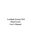
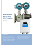
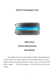
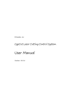
BCS100 Capacitive Height Controller User Manual Shanghai Friendess Electronic TechnologyCo.,Ltd www.fscut.com Ver3.22 BCS100 Capacitive Height Controller 2 Thank you for using our products! This Manual describes BCS100 capacitive height controller in details, including system features, operation, installation instructions etc. If you want to know more about CypCut laser cutting software that can improve the performance of height controller while using together, please refer to the help documents of the software. For any other information, please contact us directly. Please read the Manual carefully before using the controller and relevant devices, so that you can make better use of it in future. Along with continuous updating of product functions, there may be some differences between that you received and the Manual. We will apologize for any inconvenience. 3 BCS100 Capacitive Height Controller Contents Chapter 1 1 2 Chapter 2 1 2 3 Introduction to Product .............................................................................................. 5 Introduction .................................................................................................................... 5 Performance Description ................................................................................................ 5 Operating Instructions................................................................................................ 6 Description of Keys ......................................................................................................... 6 Functional Hierarchical Graph......................................................................................... 7 Main Interface................................................................................................................. 7 3.1 Hidden Functions of Main Interface ...................................................................... 8 4 Calibration Interface ....................................................................................................... 9 4.1 Servo Calibration.................................................................................................... 9 4.2 Capacitance Calibration ....................................................................................... 10 4.3 Self adjustment .................................................................................................... 12 5 Parameter Interface ...................................................................................................... 12 5.1 Technical Parameters ........................................................................................... 13 5.2 Speed Parameters ................................................................................................ 14 5.3 Origin Parameters ................................................................................................ 14 5.4 Jog Parameters..................................................................................................... 15 5.5 Mechanical Parameters ....................................................................................... 15 5.6 Network Settings ................................................................................................. 17 5.7 Alarm Settings ...................................................................................................... 18 5.8 Edge Settings ........................................................................................................ 19 6 Test Interface................................................................................................................. 19 7 Interface of Advanced Settings ..................................................................................... 20 7.1 Product Information ............................................................................................ 20 7.2 Alarm Information ............................................................................................... 21 7.3 Restart .................................................................................................................. 22 7.4 System Settings .................................................................................................... 22 7.5 Config file ............................................................................................................. 22 8 Oscilloscope .................................................................................................................. 23 Chapter 3 Installation Instructions ............................................................................................ 24 1 Introduction to Accessories .......................................................................................... 24 2 Installation Size (Unit: mm) ........................................................................................... 24 2.1 Preamplifier ......................................................................................................... 25 2.2 Master controller ................................................................................................. 26 3 Wiring Instructions........................................................................................................ 27 3.1 Interface Layout ................................................................................................... 27 3.2 Power Interface Instructions................................................................................ 27 3.3 Servo connection and setting .............................................................................. 28 3.4 Description of Input and Output Interface .......................................................... 37 3.5 Description of Sensor Interface ........................................................................... 37 4 Debugging Steps ........................................................................................................... 37 Chapter 4 Alarm process and FAQ ............................................................................................ 39 BCS100 Capacitive Height Controller 1 2 4 System alarm analysis ................................................................................................... 39 1.1 Z+/Z- limit enable ................................................................................................. 39 1.2 Out of Z range ...................................................................................................... 39 1.3 Z- limit continue enable ....................................................................................... 39 1.4 Z+ limit continue enable ...................................................................................... 39 1.5 Servo alarm .......................................................................................................... 39 1.6 Encoder moves abnormally ................................................................................. 39 1.7 Encoder no response ........................................................................................... 40 1.8 Encoder deviation large ....................................................................................... 40 1.9 Capacity is 0 ......................................................................................................... 40 1.10 Local capacity small ............................................................................................. 40 1.11 Follow deviation large .......................................................................................... 41 1.12 Sample capacity large .......................................................................................... 41 1.13 Expiration of time ................................................................................................ 41 1.14 Battery lost lock ................................................................................................... 41 1.15 Jog nearby board ................................................................................................. 41 FAQ ................................................................................................................................ 41 2.1 Obvious vibration and mechanical shock in the following movement ................ 41 2.2 The follower always hits the board during in following movement .................... 42 2.3 The following height is different from the actual height ..................................... 42 2.4 The follower cannot move up to the correct height ............................................ 43 2.5 “Validation error, failed ARM upgrading” when upgrading ................................. 43 2.6 Follower moves up without contacting the board during calibration ................. 43 5 BCS100 Capacitive Height Controller Chapter 1 Introduction to Product 1 Introduction BCS100 capacitive height controller (hereinafter referred to as BCS100) is a high-performance control device which usedclosed-loop control method. BCS100 also provides a unique Ethernet communication (TCP / IP protocol) interface, it can easily achieve many functions with CypCut software, such as automatic tracking of height, segmented piercing, progressive piercing, edge seek, leapfrog, arbitrary setting of lift-up height of cutting head.Its response rate is also improved greatly. Especially in servo control aspects, its running speed and accuracy should obviously be better than other similar products, owing to dual closed-loop algorithm of speed and position. 2 Performance Description Sampling rate: 1,000 times per second. Static measurement accuracy: 0.001 mm. Dynamic response accuracy: 0.05 mm. Following range: 0-25 mm. The signal will not decay with strong capacity of resisting when the length of signal transmission cable is up to 100m. Support network communications and U disk online upgrade. Adapt to any cutting head and nozzle. Support alarm while hitting the board and beyond the edge. Support edge detection and automatic inspection. Automatic calibration process, with fast and easy operations. Support leapfrog and segmented piecring. Support oscilloscope functions to detect the capacitance in real time. The comparison of new and old products are shown as below: Performance index BCS100 V2.0 BCS100 V3.0 MaxMoving Speed 400mm/s 999mm/s Max Acceleration 0.4G 2G Capacitance Mutation Restraint 5% 10% Min Inflexibility Requirement 5Hz 2Hz DA Resolution 12 bit 16 bit DA Zerodrift 16mv 3mv DA Response Time 5ms 0.01ms Positioning Accuracy 0.05mm 0.01mm BCS100 Capacitive Height Controller 6 Chapter 2 Operating Instructions 1 Description of Keys Keyboard Functional key Number key Decimal point Backspace key Function F1 F2 F3 F4 Achieve the functions prompted by the interface. 1 2 3 4 5 6 7 8 9 . 0 : Used for digital input, and mainly for parameter input 变速 SHF Arrow key : Used for switching cursor and inching follower, and the key of “SHF” can switch the jog speed. Control key 跟随关 SHUT 跟随快 FAST 跟随高 +0.1 停止 STOP 确定 ENT 跟随开 FOLLOW 跟随慢 SLOW 跟随低 -0.1 回原点 ORG 取消 ESC : <SHUT>: The cutting head will automatically rise to the stop position while shutting the follower. <FOLLOW>: Open the following function. <FAST> and <SLOW>: Used for adjusting the following gain level. <+0.1> and <-0.1>: Used for adjusting the following height. <STOP>: Immediately stop all movements. <ORG>: Immediately implement the movement to go back to the origin and correct mechanical coordinates. <ENT>: Confirm the current operation. <ESC>: Cancel the operation and go back. 7 2 BCS100 Capacitive Height Controller Functional Hierarchical Graph The functional hierarchy of BCS100 is as shown below: Servo calibrate Calibrate Capacitance calibrate Self adjust Technic Speed Origin Main Parameter Jog Mechanic Net Alarm Edge Test Version Alarm info Advanced Restart System set 3 Main Interface It will automatically enter<main interface>after the system is powered on and the initialization is completed, as shown below: Dynamic Error Follow level 1~9 Current State Follow height Z coordinate Current Capacity Jog Speed Function BCS100 Capacitive Height Controller 8 The displays on the main interface include: Current status: display the current motion state of the following system. The motion states are as follows: A. Stopped: Z-axis is in an idle state. B. Decel: There will be a very short transition state for slow stop after receiving a stop instruction in motion state. It will change into “stop” state after completely stopping. C. Moving: It is the movement of Z-axis while lifting up during processing. D. Follow: The follower follow the board while conduct punching and cutting operations. E. Origin: Go back to the mechanical origin of Z-axis. F. Jogging: Manually jog Z-axis. G: Lift up: It is the process to shut the follower off, and lift it to the stop position. Following gain level:The level of following gain ranges from 1 to 30. The large level is, the smaller average error is, the quicker follow acts, and the stronger slope move ability is. But if gain is too high, there may be self-oscillation. It is recommended to set this parameter by self adjustment. Following height:The actual following height can be adjusted with a step of 0.1mm after pressing the button<+0.1> and <-0.1>. The following mode can be changed through pressing <SHUT> and <FOLLOW>. After pressing “SHUT”, the axis will automatically raise to the stopping coordinates (it defaults to the position of Z= 0; the stopping coordinates can be modified after pressing<F2> to enter the parameter interface). In addition, in the Ethernet control mode, the following height is set by CypCut software. Dynamic error: In the following state, this value reflects the real-time error during following movement. Distance H between follower and board surface: Within the capacitance measurement range (calibration range), the distance between follower and board surface is “following height” plus “dynamic error”. When exceeding the measuring range, “set following height” plus “dynamic error” is identically equal to the calibration range. Current Z-axis coordinates: After homing to origin, a mechanical coordinate system is established at Z-axis. The coordinate will increase when moving down. Current capacitance value C: The principle of systematical sampling is to get the distance through measuring the capacitance between the follower and polar plate. The closer the follower is to the board, the greater the capacitance value is. The capacitance will change to Zero while the follower hits the board. Jog speed of Z-axis:<L> represents low jog speed and <H> represents high jog speed. The jog speed stalls can be switched through pressing the button <SHF>. You can press the buttons <↑> and <↓>to jog. 3.1 Key Hidden Functions of Main Interface Functions 9 <3> <4> <5> <6> <7> <9> <0> 4 BCS100 Capacitive Height Controller Set follow parameters. Real-time following error oscilloscope. Real-time monitor oscilloscope of capacitance. Capacitance-distance curve. Record the current capacitance. Start the follower of edge cutting. Set the current Z-axis coordinates to be 0. Calibration Interface In the main interface, press the key <F1> to enter<calibration interface>, as shown below: After BCS100 was installed and sued as first time, do servo calibration first. Then return origin, do capacitance calibration. At last, do self adjustment. At the next time, do capacitance calibration is enough. 4.1 Servo Calibration The purpose of servo calibration is to eliminate the zero drift of servo motor. Press the key <1> to enter the interface of<servo calibration>, as shown below: During servo calibration, the motor vibrates back and forth with small amplitude, so it is required to first jog the motor to the mid-travel, and thus prevent from exceeding the travel range while vibrating. And then press <ENT> to begin calibration. The system will return to the previous interface after completing the automatic BCS100 Capacitive Height Controller 10 calibration. 4.2 Capacitance Calibration The purpose of follower calibration is to measure the corresponding relationship of capacitance and position between the follower and board. Press <2> to enter the interface of<follower calibration>, as shown below. If no setting has been conducted before, press <F4> to set calibrated parameters. Parameter Description Calibration Distance It is required to record the capacitance data within the range for calibration, and the default is 25mm. When the travel of Z-axis is too short, users can appropriately reduce the value. Board Set the material of the following object. material Press <ENT> to save the parameters and return to the previous interface. Before calibration, first fog the follower and make it close to the board (larger than 1mm from the board), and keep the board still without vibrations. Then press <ENT> to begin calibration. The calibration process can be done automatically within ten seconds. Users can press the <Stop>button to forcibly terminate the calibration. After the calibration is complete, there are two standards, and four grades of “excellent”, “good”, “not good” and “poor” are respectively set for each standard. The automatic calibration steps are as below: 11 BCS100 Capacitive Height Controller (1). Head moves down slowly and checks if board is hit. (2).After head hits the board, moves up for 2mm, checking the stability. (3).Head moves down slowly and checks if board is hit for the second time. (4).If board is hit, head moves up for the calibrate range, checking the smoothness and the capacitance characteristic. If one of the steps is not executed, and there is alarm after calibration, hardware or connection problem should be considered. An easy way to check the problem is: touch the spray by metal and see if capacitance changes. If the change is low(in 200) or the capacitance is always 0, hardware or connection problem is proved. In addition, considered to safe and static electricity factor, touch the spray by hand when system is powered is not recommended. The meaning of calibration result is as below: Stability: It reflects the static characteristics of the capacitance. If the standard is not ideal after calibration, the reason may be due to the vibration of the board or strong external interference. Smoothness: It reflects the dynamic characteristics of the changes in capacitance during calibration. These two standards at least should be “medium”, or the system may not be able to be used normally. In relatively ideal conditions, the two standards should be “excellent” or “good”. Effective value:It‟s difference of capacity from 0.5mm nearby board to infinity. If the value is large, follow precision and stability is better. After pressing <ENT> to save the calibration results, capacitance-distance curve will be displayed. Normal curve should be smooth, as shown below: If the curve is not smooth with downs or glitches, the results are not ideal and re-calibration is required. If the results are still not ideal after repeated calibration, users should reexamine the hardware installation and wiring of the system. In addition, users can view the calibrated curve after pressing button<6> on the main interface. If calibrate failed, alarm is as shown below: Alarm Description Hit board over time When calibrating, if the cutting head moves down and check no board is hit in long time, there will be this alarm. How to check what happened? First, ensure the head is near the board before calibration (in about 5mm). Next, check if the hardware and connection are right. Last, try to do calibration again. If the head does not BCS100 Capacitive Height Controller 12 move when calibrating, maybe the resolution ratio of analog voltage output is not enough. You should try to modify the speed-voltage gain less. Leave board overtime Sample overtime Always hit board Capacity changes abnormally 4.3 Check if the hardware and connection are right. Do calibration again. Please refer to “Leave board overtime” alarm. Do calibration again. Take care jog near the board at about 1~5mm before calibration. Self adjustment Press <3>to enter the interface of<Self adjustment>, as shown below: Before adjustment, it should be confirmed as below: Servo calibration is done. Origin is done. Capacitance calibration is done. There is a board below the head to be followed. The course of adjustment is follow again and again to optimize the internal parameter. The optimization result is as shown below: Press <ENT> to save the parameters. The meaning is as shown below: Parameter Description Follow down gain lv 5 The larger it is, the faster head follows. Too large level will result in large deceleration. This parameter can be only set by self adjustment. And follow level parameter is also set at the time after adjustment. Parameter Interface On the main interface, press <F2> to enter <parameter interface>, as shown 13 BCS100 Capacitive Height Controller below: Users must correctly set the parameters above when using BCS100 for the first time. Especially, “mechanical parameters” should be set correctly, or the system cannot work normally. 5.1 Technical Parameters Press <1> to enter the interface of <technical parameters>, and the first page is as shown below: The descriptions of parameters are as shown below: Parameter Description Set Z rang. Immediately stop when exceeding the travel during running, and give an alarm of “Out of Z Rang”. Set the target location of the follower after completely processing the DockPosition program. Set a coordinate, and move to the coordinate through pressing<←> Mid Position and<→>on the main interface. Set the spacing distance between the follower and board during Punch height punching movement. When the cursor selects the parameter of “aligning position”,“stopping coordinate” or “Z-axis travel”, there will be one more menu for [F1]. And press [F1] to set the current parameters by jog mode. Press <ENT> for the following page, and continue to set process parameters. The second page is as shown below: Z-Rang BCS100 Capacitive Height Controller 14 These parameters are mainly used in I/O control mode. These parameters will not take effect in Ethernet control mode. The descriptions of the parameters are as shown below: Parameter Description IN1 following When input port 1 is effective, direct following mode is used, that mode is, punching-delay-following. Punching delay Delay time during punching. Progressive Speed when progressively follow to the cutting height. speed When dropping to the punching position, output port 4 will give a 200ms of effective signal. When dropping to the cutting height, output port 1 will give a constant effective signal. 5.2 Speed Parameters Press <2> to enter the interface of “speed parameters”, as shown below: The descriptions of parameters are as shown below: Parameter Description name Up/Down Speed of Follower: The recommended setting is that the ser Moving vo motor should run close to rated point, so as to improve efficiency a speed nd ensure stable running of system. Acceleration Set the acceleration of follower for following and moving. Maxfollow 5.3 The Max Following Speed: It depended on Acceleration and the type of the nozzle. The value increases with the increasing Acceleration, and becomeshigher with the higher capacity-sensitive nozzle. Origin Parameters Press <3> to enter the interface of <Origin parameters>, as shown below: 15 BCS100 Capacitive Height Controller The descriptions of parameters are as shown below: Parameter Description Whether to origin after power-on Whether to return to dock position Origin speed Return distance 5.4 Set whether to automatically reset after power-on, and set the option to be Yes after debugging. Set whether to go back to the set dock position after completing reset. Set the fast movement speed to go back to the origin. Set the return distance after touching the origin switch. This location is coordinate zero. Jog Parameters Press <4> to enter the interface of <jog parameters>, as shown below: The descriptions of parameters are as shown below: Parameter Description Jog speed low Set the speed of Gear L during jog movement. Jog speed high Set the speed of Gear H during jog movement. Determine whether or not to enable the soft limit while setting jog. If used, the soft limit should not jog to the position of negative Software limit coordinate or below the following height, so as to avoid hitting the limit or board during jog movement. Soft limit protection function only becomes effective on the main interface. Only the jog function on the interface of<test>is open-loop controlled. The jog function on the functional testing interface will not be affected when encoder signal is abnormal. 5.5 Mechanical Parameters Press <5> to enter the interface of <mechanical parameters>, and Page 1 is as shown below: BCS100 Capacitive Height Controller 16 Press <ENT>, Page 2 is as shown below: Press <ENT> again, Page 3 is as shown below: The descriptions of parameters are as shown below: Parameter Description Set the travel of the transmission mechanism per revolution, such as screw pitch (lead). In theory, the greater the screw lead, the Lead screw pitch faster the running of Z-axis, and it is recommended to use the ball screw with a lead of 5mm. Set the allowable upper limit of rotational speed of servo motor Max RPM(rotate according to the characteristics of motor and load. Generally, it speed per minute) does not exceed 4,500 rev / min. Set the actual rotational speed corresponding to each volt. The Speed-voltage speed should be consistent with the parameters in the driver, and gain the recommended value is 500 rev / min corresponding to each volt. Set the number of pulses fed back by the encoder of servo motor Pulses per round per revolution. The number should be consistent with the parameters in the driver. Direction of servo Set the rotation direction of servo. Direction of Set the direction of pulse feedback of encoder. encoder Servo type 0 represents the servo of Panasonic A5 、 Mitsubishi J3 series、 17 BCS100 Capacitive Height Controller Logic of limit input Logic of General input IO control mode 5.6 Schneider Lexium23D or Fuji A5. 1 represents the servo of Yaskawa Σ-V or Delta ASDA series. 2 represents the servo of Teco JSDEP series. The principles of zero-speed clamp, logic of input and output signals and system control parameters are different when the servos are different. Set the logic of limit input port (IN5~6) (0: normally opened / 1: normally closed). Set the logic of universal input port (IN1~4) (0: normally opened / 1: normally closed) If it is set to be 0, the follower will move down when IN1 is enabled, while the follower will shut when IN1 is disabled. If it is set to be 1, after IN1 become disabled, the follower can move up only after setting IN3 to be enabled. (The parameter is ignored when using network communication) Network Settings Press to enter the interface of <network settings>, as shown below: When using CypCutlaser cutting software of our company, lift up by arbitrary height, leapfrog, segmented punching; flying light path compensation and other advanced functions can be easily achieved through the network. See the manual for CypCut software for details. When not using CypCut software, please shut down the network, or start-up process will become slow. When using the network functions, it is recommended to directly connect PC and BCS100 by crossed wire. IP address of PC should be in the same network segment with BCS100 (10.1.1.xxx, which cannot be same to BCS100). The gateway should be set in the same network segment, and the last number should be 1, such as 10.1.1.1. As shown below: BCS100 Capacitive Height Controller 18 Note: When the computer is connected to other network equipments concurrently, such as IPG fiber laser (network connection mode), and each equipment should be set in different network segments. For example, the equipments can be respectively set to be 10.1.2.x and192.168.1.x. 2. After the IP of network card is reset, please disable-enable the network card again, so as to make the IP settings of the network card to take effect. 5.7 Alarm Settings Press <7> to enter the interface of <alarm settings>, as shown below: Parameter name Max follow deviation Description It is the maximum allowable following error of BCS100. After the cutting head is in place, the controller will give an alarm for too large following error if the following error exceeds the set alarm value due to the movement beyond the plate boundary or severe vibrations of board. 19 BCS100 Capacitive Height Controller Max follow delay Hit board delay Stop hit alarm enable Limit alarm 5.8 Set the filter time of following error alarm. The greater the value, the slower the response and the stronger the ability to filter out interference. When the follower hits the board and the duration reaches the time limit, the follower will automatically move up for protection and output alarm signal. This parameter indicates if hit board alarm is active when the follower is in stop state. It is safer when the value equals 1. And when you need to adjust the center of laser by stick adhesive tape, or when you do not want the controller always alarm in no plastic film, it is convenient to set it to 0. When it is set to be 1, upper and lower limit alarm function will be started. The follower will automatically move up when encountering upper / lower limit and then give an alarm signal. When it is set to be 0, alarm function is disabled. Edge Settings Press <8> to enter the interface of <edge settings>, as shown below: Parameter name Description Saturation speed The max speed to follow down after head cutting out of board to prevent deep drop damage. When check the H is lower than this parameter, the head start follow. Cut in check Cut out check Cut out delay Height 6 If it is checked that H position is larger than cut “cut out check” and last more than “cut out delay”. Through cut height: Set the Z position to locate to before following. Test Interface On the main interface, press <F3> to enter the interface of <functional test>, as shown below: BCS100 Capacitive Height Controller 20 Users can test whether the state of keys, input and output ports and the rotation direction of motor are correct. After completing the installation for the first time, users must enter the interface for switch jog to determine whether the rotation direction of motor and the director of encoder signal are correct. If the rotation direction of motor is incorrect, users need to modify the “servo direction” parameters in “mechanical parameters”, and then conduct open-loop jog to determine whether the direction of encoder signal is correct. If it is prompted that the direction of encoder is incorrect, users need to modify the “encoder direction” parameters in “mechanical parameters”. The input and output ports of the interface are defined as below: Input Definition Outpu Definition port t port IN1 Follow to cutting height OUT1 Signal for following to place IN2 Move to aligning coordinate OUT2 Stay to position signal IN3 Lift-up signal OUT3 Alarm output signal IN4 Stopping signal OUT4 Punching signal IN5 Negative limit OUT5 Servo clearing alarm (servo signal) IN6 Positive limit OUT6 Servo enabled (servo signal) IN7 Servo alarm (servo signal) OUT7 Zero speed clamp (servo signal) 7 Interface of Advanced Settings On the main interface, press <F4> to enter the interface of <advanced settings>, as shown below: 7.1 Product Information Press <1> to enter the interface of <product information>, as shown below: 21 BCS100 Capacitive Height Controller Users can view the following on this interface: Information Description ID number For example v3.0.3032 is program version number.“2D” represents being used for plane cutting. “3D” represents being used for 3D mechanical cutting. BCS100 global only serial number. Such as 201111180100 Expiration The remaining time for BCS100, such as 30 days or unlimited. Version Current Time BCS100 current internal date We will release a new version of the program regularly. The update step is shown as below: 1. Find a U disc, format it to FAT/FAT32 (we don't support NTFS format) 2. Copy the upgrade files to the root directory of the U disc, do not rename the files.(For BCS100V2.0, there is two files named <BCS.AFM> and<BCS.FFM>. For BCS100V3.0, there is only one file named <BCV3.AFM>) 3. Insert the U disc to BCS100's USB interface. 4. Reboot the BCS100 (Method 1:Power off then power on. Method 2: Use the„restart‟ function) 5. Wait until upgrade progress bar 100%finish, then the buzzer beep. 6. Remove the U disc. Check the software version. When the service time of BCS100 expires, alarm information (service time expires) will be displayed on the main interface, and key functions cannot be implemented, such as following. Users can press [F1] to register and enter <registration interface>, and then continue to use the height controller after inputting the correct registration code. 7.2 Alarm Information Press <2> to enter the interface of <alarm information>, as shown below: BCS100 Capacitive Height Controller 22 In this interface, the previous alarm events are displayed in a list. The system can record as many as 20 alarm events. Users can clear the alarm list after pressing <F1>. Users can refer the meaning of each alarm to Chapter 5. 7.3 Restart Users can press <3> to restart BCS controller. This operation is equal to that the system is powered down and then powered on. Users can first insert USB disk to BCS when they want to upgrade the program, and complete the upgrade with restart function, which can avoid the trouble to power down and then power on the system. 7.4 System Settings Users can press <4> for system settings, and then enter the interface of <system settings> after inputting the password of 61259023. Parameter Description Application 0: plane cutting applications. 1: 3D cutting application. Language User configuration 0: Chinese version. 1: English version. Parameter protect 7.5 Special customization function 0: Parameters are not encrypted. 1: Parameters are encrypted. Users need to enter the password if they want to modify the parameters. Password: 11111111 Config file Press <5> to enter config file interface, is as shown below: 23 BCS100 Capacitive Height Controller The function of configuration file includes: Copy parameter of specify machine to all same type machines. Make boot logo of BCS100. Back up BCS100‟s parameter. Make notice of: Use a USB disk with FAT/FAT32 format. The configuration file‟s format is xxx.CFG. When import file from USB disk, make sure there is only one .CFG file at the root directory of the disk. The file export to USB disk named EXPORT.CFG. If there is a file EXPORT.CFG in the USB disk before exporting. This file will be covered. 8 Oscilloscope Oscilloscope function is one of the unique functions of BCS100. Users can enter the interface of <capacitance oscilloscope> after pressing <5> on the main interface. The principle of the oscilloscope is to display capacitance value C in real time. It also displays the maximum value (MAX), minimum value (MIN), difference between the MAX and MIN (DIF) and average value (AVE) of the measured capacitance. As shown below: Please observe the changes of capacitance while keeping the cutting head and board stationary. The greater DIF value, the greater the interference, or the more unstable the capacitance is. Users can determine the interference size in reference with the values below: DIF value Interference size 0~10 None 10~20 Very little 20~30 Little 30~50 Average 50 以上 Large BCS100 Capacitive Height Controller 24 Chapter 3 Installation Instructions 1 Introduction to Accessories Capacitance control system is composed of BCS100 controller, preamplifier, laser cutting head and cable, as shown below: Accessory name Master controller Preamplifier Thermostable cable Sensor signal cable Servo drive cable Number 1 1 1 1 1 Standard type BCS100 BCL_AMP SPC-140(140mm) HC-15(15m) C15-2.5(2.5m) DB15 plug (pin) DB15 plug (jack) Manual 1 1 1 DB15M DB15F 2 Installation Size (Unit: mm) Optional type SPC-180(180mm) HC-15(20m) C15-1.5(1.5m), C15-4(4m) Preamplifier The appearance and installation size of preamplifier is as shown below: Appearance of amplifier 36 2.1 BCS100 Capacitive Height Controller 44 25 Φ3.5×4 39 31 Installation of amplifier BCS100 Capacitive Height Controller 2.2 26 Master controller The appearance and installation size of preamplifier is as shown below: Front view 236 225 BCS100 V3.0 HEIGHT CONTROL BCS100 V3.0 controller 145 156 >>>>>>>>>>>>>>>>>----------- 跟随关 SHUT 跟随快 FAST 跟随高 +0.1 停止 STOP 跟随开 FOLL OW 跟随慢 SLOW 跟随低 -0.1 回原点 ORG F1 1 2 3 F2 4 5 6 F3 7 8 9 F4 . 0 确定 ENT 变速 SHF 取消 ESC 4-Φ4.5 217 34 8 137 Top view Left view 27 3 3.1 BCS100 Capacitive Height Controller Wiring Instructions Interface Layout The detailed interface layout of BCS100 wiring terminal is as shown below: Dorsal view USB 8 Sensor 3.2 7 6 5 4 3 2 24V 0V FG 9 10 11 12 13 14 15 15 14 13 12 11 10 9 1 Input and output 1 2 3 4 5 Servo 6 7 8 Net Power Power Interface Instructions 24V 0V FG To machine main metal part The machine casing is the negative electrode of the measured capacitor. In order to ensure the steady operation of measured circuit, it is required to reliably connect “FG pin” of power interface to the machine casing (i.e., have good conduction with machine casing), and preamplifier casing also must have good conduction with machine casing. The specific indicator is that D.C. impedance is always less than 10 Ω, or the actual following effect may be poor. BCS100 Capacitive Height Controller 3.3 28 Servo connection and setting 8 7 6 5 4 3 2 1 15 14 13 12 11 10 9 Pin 1 2 3 4 5 6 7 8 9 10 11 12 13 14 15 Color Yellow Blue Black Orange Red Green Green-black Brown Yellow-black Blue-black Black-white Orange-black Red-black Purple Brown-black Signal name DA (with an analog output of -10~10V) 0S (Zero speed clamp) A+ (Encoder A+) B+ (Encoder B+) Z+ (Encoder Z+) SON (Servo on) CLR (Clear alarm) 24V (Power output) AGND (Analog ground) 0V (Power ground) (Encoder A-) (Encoder B-) Z- (Encoder Z-) ALM (Alarm signal) 0V (Power ground) 29 BCS100 Capacitive Height Controller Wiring diagram of Panasonic servo BCS100 servo interface Panasonic MINAS-A servo 50 pin interface shielded wire Pin DA AGND No. 1 9 A+ AB+ BZ+ Z- 3 11 4 12 5 13 21 22 48 49 23 24 OA+ OAOB+ OBOZ+ OZ- 24V 8 0S SON CLR 0V ALM 0V 2 6 7 10 14 15 7 26 29 31 36 37 41 COM+ ZEROSPD SRV-ON A-CLR ALMALM+ COM- No. PIN 14 SPR/TRQR 15 GND Corresponding to the wiring modes above, the servo parameters are set as follows: Panasonic A5 series: Parameter Recommended Description No. value Pr001 1 Control mode: It must be set speed mode. Pr002 3 Real-time automatic adjustment: The recommended setting is vertical axis mode. Pr003 17 Servo rigidity, the recommended range is from Grade 14 to Grade 20. Pr302 500 Input the gain of speed command. Pr315 1 Enable zero speed clamp function. BCS100 Capacitive Height Controller 30 Wiring diagram of Yaskawa servo BCS100 servo interface Pin DA AGND No. 1 9 A+ AB+ BZ+ Z- Yaskawa Σ-V servo 50 pin interface shielded wire No. 5 6 Pin V-REF SG 3 11 4 12 5 13 33 34 35 36 19 20 PAO /PAO PBO /PBO PCO /PCO 24V 8 0S SON CLR 0V ALM 0V 2 6 7 10 14 15 47 +24 VIN 41 /P-CON 40 /S-ON 44 /ALM-RST 32 ALM31 ALM+ 1 SG Yaskawa Σ-V series: Parameter Recommended No. value Pn000 00A0 Pn00B - Pn212 2500 Pn300 6.00 Pn501 Pn50A Pn50B 10000 8100 6548 Description Speed control with zero-position fixation function. Set to 0100 when using single-phase power. Number of pulses output by the encoder per revolution. The pulse parameter of corresponding BCS100 per revolution is 10,000. The speed gain of corresponding height controller is 500 r/v/min. Zero fixed value. Forward rotation is enabled. Reverse rotation is enabled. 31 BCS100 Capacitive Height Controller Wiring diagram of Delta servo BCS100 servo interface Pin No. DA 1 AGND 9 Delta ASD-A servo 50 pin interface shielded wire No. Pin 42 V-REF 44 GND A+ AB+ BZ+ Z- 3 11 4 12 5 13 21 22 25 23 50 24 OA /OA OB /OB OZ /OZ 24V 8 0S SON CLR 0V ALM 0V 2 6 7 10 14 15 11 10 9 33 45 28 27 COM+ DI2 DI1 SON DI5 ARST COMDO5+ ALRM DO5- Delta ASD-A series: Parameter Recommended No. value P1-01 0002 P1-38 P1-40 2000 5000 P2-10 P2-11 P2-12 101 105 114 P2-13 115 P2-14 P2-22 102 007 Description Control mode: It must be set to speed control mode. Set zero speed clamp value to the maximum. The speed gain of corresponding height controller is 500 r/v/min. Set DI1 to SON, normally opened. Set DI2 to CLAMP, normally opened. Set speed command to external analog control. Set speed command to external analog control. Set DI5 to ARST, normally opened. Set DO5 to ALRM, normal close. BCS100 Capacitive Height Controller 32 Wiring diagram of Teco servo Teco JSDEP servo 50 pin interface BCS100 servo interface shielded wire No. Pin 12 SIC 13 AG Pin DA AGND No. 1 9 A+ AB+ BZ+ Z- 3 11 4 12 5 13 21 PA 9 /PA 22 PB 10 /PB 23 PZ 13 /PZ 24V 8 0S SON CLR 0V ALM 0V 2 6 7 10 14 15 17 DICOM 15 DI-4 9 DI-1 Teco JSDEP series: Parameter Recommended No. value Cn001 1 Cn002.2 1 Cn005 2500 Cn026 4 Sn216 4000 24 IG 19 DO-2 Description Control mode: It must be set to speed control mode. Automatic gain. (Note: It is the parameter of the second figure of Cn002 ) Number of pulses output by the encoder per revolution. The number of pulses of corresponding BCS100 per revolution is 10,000 Rigidity. Level 4 is the default. Speed gain. The speed gain of corresponding BCS100 is 400. 33 BCS100 Capacitive Height Controller Wiring diagram of Mitsubishi MR-J30A servo BCS100 servo interface Mitsubishi MR-J30A servo shielded wire Pin No. No. Pin DA AGND 1 9 2 VC 28 LG A+ AB+ BZ+ Z- 3 11 4 12 5 13 4 5 6 7 8 9 LA LAR LB LBR LZ LZR 24V 8 0S SON CLR 0V ALM 0V 2 6 7 10 14 15 20 17 15 19 46 48 42 DICOM ST1 SON RES DOCOM ALM EMG Mitsubishi MR-J30Aseries: Parameter Recommended Description No. value PA01 2 Control mode: It must be set to speed control mode. PA15 10000 Number of pulses output by the encoder per revolution. The number of pulses of corresponding BCS100 per revolution is 10,000 PC12 5000 Speed gain. The speed gain of corresponding BCS100 is 500 r/v/min PC17 0 BCS100 Capacitive Height Controller 34 Wiring diagram of Schneider Lexium 23D BCS100 servo interface Schneider Lexium 23D shielded wire Pin DA AGND No. 1 9 A+ AB+ BZ+ Z- 3 11 4 12 5 13 21 22 25 23 50 24 OA /OA OB /OB OC /OC 24V 8 0S SON CLR 0V ALM 0V 2 6 7 10 14 15 11 34 9 33 45 28 27 COM+ DI3 SON ARST COMDO5+ DO5- Schneider Lexium 23D Parameter Recommended No. value P2-10 101 P2-11 0 P2-12 5 P2-13~P2-17 0 P1-38 400 P1-01 2 P1-40 5000 P1-46 2500 No. Pin 42 V-REF 44 GND Description Servo IN1 function: SON Servo IN2 function: Not used Servo IN2 function: ZClamp Servo IN4~IN8 function: Not used It‟s 40.0RPM, the zero compare value Control mode: It must be set to speed control mode. Speed gain. The speed gain of corresponding BCS100 is 500 r/v/min Number of pulses output by the encoder per revolution. The number of pulses of corresponding BCS100 per revolution is 10,000 35 BCS100 Capacitive Height Controller Wiring diagram of Fuji ALPHA5 servo BCS100 servo interface Pin DA AGND No. 1 9 Fuji ALPHA5 26-Pin interface Shielded wire No. 22 13 Pin VREF M5 A+ AB+ BZ+ Z- 3 11 4 12 5 13 9 10 11 12 23 24 FFA *FFA FFB *FFB FFZ *FFZ 24V 8 0S SON CLR 0V ALM 2 6 7 10 14 1 4 2 3 14 17 P24 CONT3 CONT1 CONT2 COMOUT OUT3 Fuji ALPHA5series: Parameter Recommended Description No. value PA-101 01 Control mode: It must be set to speed control mode. PA-108 2500 Number of pulses output by the encoder per revolution. The number of pulses of corresponding BCS100 per revolution is 10,000 PA-115 17 Servo rigidity, the recommended range is from Grade 14 to Grade 20. PA-303 02 Forward rotation is enabled. PA-331 6.0 The speed gain of corresponding height controller is 500 r/v/min. BCS100 Capacitive Height Controller 36 Wiring diagram of SANYO R servo BCS100 servo interface Pin DA AGND A+ AB+ BZ+ Z- 3 11 4 12 5 13 24V 8 0S SON CLR 0V ALM 2 6 7 10 14 Parameter No. SY08 Gr0.00 Gr8.25 Gr9.00 Gr9.01 Gr9.26 GrB.13 GrB.14 GrC.05 No. 1 9 Recomme nded value 01 00 5000 00 00 00 0 0 2500/8192 SANYO R 50-Pin interface Shielded wire No. 21 20 Pin V-REF SG 3 4 5 6 7 8 A0+ A0B0+ BOZO+ ZO- 49 50 36 37 15 24 46 OUT-PWR CONT-COM CONT2 CONT1 CONT8 OUT-COM OUT8 Description Speed control mode Auto tune Speed gain. The speed gain of corresponding BCS100 is 500 r/v/min Motor rotate CW enable Motor rotate CCW enable Shut down servo gain switch Number of pulses output by the encoder per revolution. The number of pulses of corresponding BCS100 per revolution is 10,000 37 3.4 BCS100 Capacitive Height Controller Description of Input and Output Interface 1 2 3 4 5 6 7 8 9 10 11 12 13 14 15 15-pin male input and output interface Pin Signal definition 1 24V (Power output) 2 IN8(General input) 3 OUT1 (Cutting in place) 4 OUT3 (Alarm) 5 IN1 (Cutting tracking) Pin 9 10 11 12 13 6 7 8 Signal definition IN7(General input) IN9(General input) OUT2 (Stay to position signal) OUT4 (Punching in place) IN2 (Move to aligning coordinate) IN4 (Stop) IN6 (Lower limit) IN3 (Quick lift up) 14 IN5 (Upper limit) 15 0V (Power ground) Notes: 1. Output ports (OUT1~OUT4) are all open drain output, and they are connected with the power ground for outputting. 2. Input ports (IN1~IN9) are all active low level input, and the input is enabled when the input ports are connected with the power ground. 3. When the cutting head punches to place, OUT4 will output a desired signal with a width of 200ms. When the cutting lead follows to the cutting height, OUT1 will output continuous desired signal. 3.5 Description of Sensor Interface 1 4 2 3 1:Connect 2:Connect 3:Connect 4:Connect with with with with pin 1 of the cable pin 2 of the cable pin 3 of the cable shield of the cable 4-pin signal transmission cable of sensor can be manufactured with 3-pin shielded cable and 2 4-pin air plugs. It is required to connect Pin, 1, 2 and 3 together, and connect Pin 4 to shielding layer during the manufacturing process. 4 Debugging Steps After the installation, users need to debug the controller as follows: Set servo parameters. See “servo parameters” in Chapter V for details. After powering on and completing the initialization, enter the parameter interface BCS100 Capacitive Height Controller 38 and set “mechanical parameters”. Go back to <main interface> to check whether the travel switch is enabled. If it is an optoelectronic switch, the interface will display “upper limit is enabled” when blocking the upper limit with shade; it will display “lower limit is enabled” when blocking the lower limit. Enter <test interface> to conduct open-loop jog, and check whether the rotation direction of motor is right. If the direction is wrong, please change the servo direction parameters. And then conduct open-loop jog again, please change the encoder direction parameters if the encoder signal is inverse (mechanical parameters). Enter <calibration interface>, and conduct “servo calibration” to eliminate the zero shift of servo. Return to the origin manually, and turn on the power-on reset function on the interface of <reset parameters>. Enter <calibration interface> and do “capacitance calibration” for the follower. Modify other parameters as required after completing the steps above. 39 BCS100 Capacitive Height Controller Chapter 4 Alarm process and FAQ 1 System alarm analysis 1.1 Z+/Z- limit enable When system checked Z+/Z- limit input is enabled, the alarm happens. The reason includes: Z+/Z- sensor detect something. Z+/Z- sensor is broken. Or it is used for long time, there is oil contamination and powder on the surface. The parameter of “Limit logic” can be set to normal open or normal close The wiring is not correct. 1.2 Out of Z range When Z moves large then range, which is a parameter of system, the alarm will be throw out. If it is wrong alarmed, take attention in the range parameter, if the system returned origin, and if the encoder feedback is correct. 1.3 Z- limit continue enable When system is returning origin, it moves back when z- sensor is enabled, but can‟t quit the z- sensor enable area, the alarm happens. Take attention if the sensor is broken. 1.4 Z+ limit continue enable When system is returning origin, it moves back to positive axis,but come to the z+ sensor enable area, the alarm happens. Take attention whether the Aligning coordinate or Dock coordinate is too large. 1.5 Servo alarm When system checked NO. 14 input ALM is enabled, which reflect the servo alarm status, the alarm is shown on the screen. The reason of servo alarm includes: The servo alarms. The “Servo Type” parameter is not correctly set. Wiring is not correct. Electrical system disturbs the wire. 1.6 Encoder moves abnormally When system keeps in stop status, the encoder feedback value changed, there will be this alarm. The reason lead to the alarm includes: The axis vibrates by outside force. Wiring wrong, the zero speed signal does no effect. BCS100 Capacitive Height Controller 40 Servo rigidity is very low. The encoder wire is disturbed. The shield is needed, and should be connect to the ground. Add some wire magnet ring is better. 1.7 Encoder no response The system try to move, send out speed command as voltage, but the encoder feedback value does not change at all. The alarm happens. The reason includes: Wring error. Servo type is wrong. Servo must have speed control mode. Servo parameter is not correctly set. It should be switched to speed control mode. 1.8 Encoder deviation large When thedifference between destination position and feedback position is too large, the alarm happens. It reflects the servo can‟t follow the speed command correctly. The reason includes: Encoder feedback direction is wrong. The relative parameter should be modified. Wiring error or disturb make the encoder feedback wrong. The mechanic is stuck, the really position can‟t follow the destination position. 1.9 Capacity is 0 When system can‟t check the capacity of the spray, the capacity value is shown as 0 on the screen. The following situation may cause the alarm: The spray touched the board below. There is water in cutting head. The local capacity of the cutting head is large, which is out of the check range of the preamplifier. The preamplifier is broken. Connection is not fixed. In the internal of cutting head, the positive of capacity (spray) is short circle with the negative of capacity (the shell of machine). 1.10 Local capacity small When local capacity changes less, the alarm happens. The reason includes: Connection or some part is changed or moved. You can do calibration again. Laser shoots on the spray, the temperature gets very high is short time. Man‟s hands can‟t stay on the pray. Blow leads to the change of distance of positive pole (spray) and negative pole (shell of the machine). Connection is not fixed. The parameter of calibration range is low can also lead the alarm. In 2D mode 15mm is recommended. And 10mm is recommended in 3D mode. 41 BCS100 Capacitive Height Controller One of the reason is the cutting fire and electronic affects the capacity sensor when the boardmaterial is stainless steel. If there is plastic film on the surface of steel, remove the film first. Check if the machine is connect to the ground well. The following height should be large than 0.5 mm. Improve the blowing pressure. 1.11 Follow deviation large When system check the H height (the distance between spray and board) changes large in short time in follow state, the alarm happens. The relative parameter is interpreted in Chapter 2.5.5. The alarm reason includes: Cut out of the board. There is nothing to follow below. Board is vibrating heavily. 1.12 Sample capacity large When sampled capacity is larger than the largest capacity in calibration, the alarm happens. The reason includes: The spray touched the board below. There is water in cutting head. Connection is not fixed. In the internal of cutting head, the positive of capacity (spray) is short circle with the negative of capacity (the shell of machine). 1.13 Expiration of time There is no more time permitted to use this system. 1.14 Battery lost lock When unpacked the battery of the unregistered controller, the alarm happens. User can remove the alarm by registering the controller. 1.15 2 2.1 Jog nearby board When jogging the follower near the board, the alarm happens. FAQ Obvious vibration and mechanical shock in the following movement Amplifier casing or controller FG pin are poorly connected to the machine casing. Machine casing is the negative electrode of the measured capacitor. When the conductivity of amplifier casing and machine casing is poor, the AC impedance between the positive and negative electrodes of the capacitor is large. Thus, the load of measured circuit varies, which may lead to larger measurement error. If good mechanical connection cannot be achieved, users can add a wide wire(copper material is better) between amplifier metal casings to reduce AC impedance. The AC impedance of single-point connection is greater than that of good mechanical connection. It is BCS100 Capacitive Height Controller 42 required to make the AC impedance less than 10 ohms. Too large servo rigidity Mechanical shock and obvious vibration may be caused during the movement due to too large servo rigidity. For example, it is recommended that the servo rigidity of Panasonic MINAS A5 series should not be above Level 19. Too large following speed level Vibration may be caused during the movement due to too large following speed level. Level 3 to 7 are recommended. Poor follower calibration When the data stability and smoothness of capacitance and position stored in BCS100 is poor, vibration will be caused during the following movement. Please do follower capacitance calibration again, until the stability and smoothness becomes excellent or good. If there is a large interference at the field, users can appropriately reduce the parameter of “servo gain coefficient”. 2.2 The follower always hits the board during in following movement Too small calibration range or too large Z-axis speed The smaller the calibration range, the smaller the deceleration distance of following movement. If Z-axis speed is too large and it is not reduced to 0 when the follower flows to place, overshoot will be unavoidable. The greater the Z-axis speed is, the greater the overshoot is. When Z-axis speed is greater than 100mm/s, it is recommended to set the calibration range to be 15mm. When Z-axis speed is greater than 250mm/s, it is recommended to set the calibration range to be 20 to 25mm. Too small servo rigidity Servo response may lag behind the control signals of controllers due to too small servo rigidity, and thus the follower will hit the board. For example, it is recommended that the rigidity of Panasonic MINAS A5 series should not be below Level 13. Capacitance calibration The follower will hit the board when there is a large deviation between the capacitance stored in BCS100 and actual measured capacitance. For example, the nozzle temperature increases a lot or the connection is not stable. Users need to first find the reason, and then calibrate capacitance again after solving the problem. No preheating Please preheat the amplifier for 2 to 5 minutes, and then operate BCS100 controller after the sampling capacitance in the amplifier becomes stable. The locking nut of ceramic part is not connected tightly. The locking nut of ceramic part is not connected tightly, which may lead to instable detecting capacitance. 2.3 The following height is different from the actual height No preheating Please preheat the preamplifier for 2 to 5 minutes, and then operate BCS100 controller. The sampling capacitance in the preamplifier may changes with the changes 43 BCS100 Capacitive Height Controller in temperature. Please preheat the amplifier for 2 to 5 minutes, and then operate BCS100 controller after the sampling capacitance in the amplifier becomes stable. Calibration problem The phenomenon above often appears if the follower capacitance is not calibrated again after replacing the nozzle. Nozzle temperature increases abnormally (above 100oC) because the laser scatter to the nozzle or the blowing is abnormal, and thus the capacitance of cutting head changes. The follower does not hit the board in intelligent calibration, and the actual following height is higher than the setting height. Please do calibration after closing the intelligent check option. 2.4 The follower cannot move up to the correct height If the follower cannot move up or the lift-up height is incorrect, users need to first observe and determine whether Z-axis coordinates are normal. If Z-axis coordinates get less obviously, it is required to first return to the origin, press repeatedly “FOLLOW” and “SHUT”, and then obverse whether Z-axis coordinates are consistent with each other after following to the board. If Z-axis coordinates continue to decrease, there may be a problem in the position feedback of the system. The reason may be that: servo motor or ball screw and coupling slide against each other, resulting in coordinate offset. 2.5 “Validation error, failed ARM upgrading” when upgrading Upgrade file may be infected by computer virus. 2.6 Follower moves up without contacting the board during calibration Please check the follow material is set to “metal” or “nonmetal”