1
MN05006002Z-EN
Electrical Installation
Electrical Installation
Potential conditions between the components
The entire SWD topology operates with a common device
supply voltage. The field bus and the SWD topology are electrically isolated from one another.
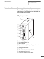
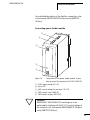
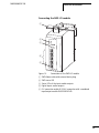
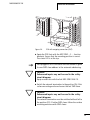
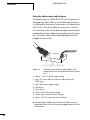
SWD gateway connection
g
f
e
d
c
b
a
h
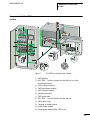
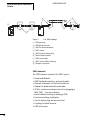
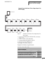
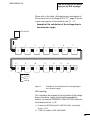
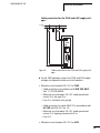
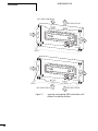
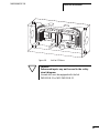
Figure 8:
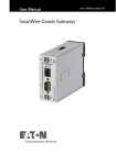
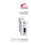
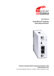
SWD gateway
a POW: Supply voltage 24 V DC
b Field bus interface
c Diagnosis interface, only for diagnostic purposes in case of
service
d Config. pushbutton actuator
e Status LEDs
f AUX: control voltage for contactors 24 V DC
g SWD network output (SWD OUT)
h DIP switch for setting the field bus address
47