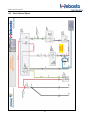
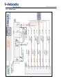
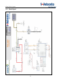
1
™ O-Zone-Tech II INSTALLATION MANUAL Ford Crown Victoria O-Zone Tech IITM System CONTENTS 1. INTRODUCTION ................................................................................................................................................. 5 1.1. 1.2. 1.3. 1.4. 1.5. Scope ........................................................................................................................................................... 5 Applicability of Manual ................................................................................................................................. 5 Meaning of Warnings, Cautions and Notes .................................................................................................. 5 Safety ........................................................................................................................................................... 5 Legal Provisions for Installation ..................................................................................................................... 5 2. PARTS LIST ......................................................................................................................................................... 6 3. SYSTEM OVERVIEW .......................................................................................................................................... 7 3.1. System Modes .............................................................................................................................................. 7 3.1.1. Idle Reduction Mode ............................................................................................................................. 7 3.1.2. Keyless Mode ........................................................................................................................................ 8 3.1.3. Anti-theft Mode (Optional) .................................................................................................................... 8 3.2. Software....................................................................................................................................................... 8 4. HARDWARE INSTALLATION ............................................................................................................................. 9 4.1. 4.2. 4.3. 4.4. 4.5. 4.6. 4.7. 4.8. 4.9. 4.10. 4.11. 4.12. 4.13. 4.14. 4.15. 4.16. 4.17. 5. Layout .......................................................................................................................................................... 9 Preliminary Information .............................................................................................................................. 10 Ignition Switch Connection......................................................................................................................... 13 Module Mounting ...................................................................................................................................... 14 Ground Connection .................................................................................................................................... 15 Brake Signal Connection............................................................................................................................. 15 Keyless Switch Wiring ................................................................................................................................. 16 Temperature Sensor (Outside Temperature) ................................................................................................ 17 Webasto Heater Connection....................................................................................................................... 19 Temperature Sensor (Inside Temperature) ............................................................................................... 21 Wiring Feed to Engine Compartment ...................................................................................................... 22 Park Signal Connection ........................................................................................................................... 22 Hood Switch ........................................................................................................................................... 23 RPM Signal.............................................................................................................................................. 24 Anti-theft Mode ...................................................................................................................................... 25 Radio / Computer Connection................................................................................................................. 26 Emergency Lights Connection ................................................................................................................. 26 SOFTWARE....................................................................................................................................................... 27 5.1. Software Compatibility ............................................................................................................................... 27 5.2. Software Installation ................................................................................................................................... 28 5.3. Navigation Menu ........................................................................................................................................ 29 5.3.1. Configuration ...................................................................................................................................... 29 5.3.2. Connect .............................................................................................................................................. 29 5.3.3. Analyze IDLE ....................................................................................................................................... 30 5.3.4. Download ........................................................................................................................................... 31 5.3.5. Full Version ......................................................................................................................................... 31 5.4. Window Explanation .................................................................................................................................. 31 5.4.1. Vehicle information ............................................................................................................................. 32 5.4.2. Error Status ......................................................................................................................................... 32 3 O-Zone-Tech-II™ System 5.4.3. 5.4.4. 5.4.5. 5.4.6. 5.4.7. 5.4.8. 5.4.9. 5.4.10. 6. Version ................................................................................................................................................ 32 Reading All .......................................................................................................................................... 32 Status Tray Fields ................................................................................................................................. 33 Keyless Mode Duration........................................................................................................................ 33 Main Outputs ...................................................................................................................................... 33 Auxiliary Outputs ................................................................................................................................. 34 Inputs Configuration ........................................................................................................................... 34 Start Engine Conditions ................................................................................................................... 35 LED SCENARIOS ............................................................................................................................................... 36 6.1. Module....................................................................................................................................................... 36 6.1.1. Green LED: .......................................................................................................................................... 36 6.1.2. Red LED:.............................................................................................................................................. 36 6.2. Switch ........................................................................................................................................................ 36 7. FINAL INSPECTION (CHECKLIST) ..................................................................................................................... 37 8. INITIAL START-UP ............................................................................................................................................ 38 8.1. Start-up: ..................................................................................................................................................... 38 8.1.1. Idle Reduction Mode ........................................................................................................................... 38 8.1.2. Keyless Mode ...................................................................................................................................... 38 8.1.3. Anti-theft Mode (Optional) .................................................................................................................. 39 9. TECHNICAL DATA ............................................................................................................................................ 40 9.1. 9.2. 10. Technical: ................................................................................................................................................... 40 Mechanical: ................................................................................................................................................ 40 O-ZONE-TECH II™CONNECTIONS OVERVIEW ........................................................................................... 41 10.1. 11. Connection Description........................................................................................................................... 42 WIRING DIAGRAMS ..................................................................................................................................... 43 11.1. 11.2. 11.3. 11.4. 11.5. 11.6. Complete ................................................................................................................................................ 43 Ignition Signal ......................................................................................................................................... 44 Park / Neutral Signal................................................................................................................................ 45 RPM Signal.............................................................................................................................................. 46 Brake Signal ............................................................................................................................................ 47 Heater Connections ................................................................................................................................ 48 12. TROUBLESHOOTING .................................................................................................................................... 49 13. LIMITED WARRANTY ................................................................................................................................... 57 4 O-Zone Tech IITM System 1. INTRODUCTION 1.1. Scope These non-binding installation instructions are intended to support authorized Webasto trained distributors, dealers and personnel in the installation of the O-Zone-Tech II™ System. 1.2. Applicability of Manual These non-binding installation instructions apply to the vehicles listed on the front cover of this installation manual unless technical modifications on the vehicle influence the installation, excluding all liability claims. Depending on the version and equipment in the vehicle, changes may be required to the installation work set out in these installation instructions. In any event, the directives in the “Installation Manual” of the O-Zone-Tech II™ system must be followed. Acknowledged engineering conventions must be observed for the installation work. CAUTION Location of the O-Zone-Tech II™ module, wiring and control devices are important for proper operation. Failure to comply with the installation instructions provided may result in poor operation or damage to the module and/or to the vehicle or vehicle components. 1.3. Meaning of Warnings, Cautions and Notes WARNING This heading is used to highlight that non-compliance with instructions or procedures may cause injuries or lethal accidents to personnel. CAUTION This heading is used to highlight that non-compliance with instructions or procedures may cause damage to equipment. NOTE This heading is used to highlight and draw specific attention to information. CAUTION Non-compliance with the installation instructions and information contained therein will void the warranty. The same applies for repairs performed by unskilled personnel and repairs using not original spare parts. 1.4. Safety All relevant state and provincial regulations if any, governing the installation and use of non idling devices must be observed! The general safety regulations for the prevention of accidents and the relevant operating safety instructions must be observed at all times. 1.5. Legal Provisions for Installation Vehicle operation must not be impaired due to any O-Zone–Tech IITM components. All power circuits must be fused with appropriate fuse or circuit breaker. 5 O-Zone-Tech-II™ System 2. PARTS LIST Vehicle Make Ford Model Crown Victoria Included in box Item O-Zone-Tech-IITM P/N 1 2 3 4 OZWB-00-1000-B ASY-KITOZWB-HARCV ASY-KITOZWB-ICV LCN-250-3200Y Year 2005 - 2011 Webasto Kit Number 5010293A Description Fuel saver & CO2 reducer O-Zone-Tech-II module & bracket Kit includes: - OZWB-00-1000 (O-Zone-Tech II module) Bracket kit include: -ZM-SUP-OZTC-ALU (Aluminum one piece bracket) -VIS08-91772A194 (Phillips Screw Pan, #8-32x1/2", Stainless) -VIS08-91831A009 (Hex Locknut, Nylon, #8-32, Stainless) O-Zone-Tech-II C1, C2 & C3 harnesses for Crown Victoria with housing for C6 and C11. Kit includes: -C1 Harness (ASY-CBLOZTC-C1-CV) -C2 Harness (ASY-CBLOZWB-C2-CV) -C3 Harness (ASY-CBLOZWB-C3-CV) -CON-WPF2C (Housing for C6 and C11) O-Zone-Tech-II installation kit for Crown Victoria Kit includes: -LCN-350-2000Y (High temperature loom 3/8'') - 315-709 (Grommet ½'') - 315-733 (Grommet 11/16”) -S-2154FY (Tie rap) -PWMS-H25-MO (Tie-rap holder, push mount) -11612 (Push pin retainer) -CON-BUTSTR14-16 (Butt splice gage 14 - 16) -CON-BUTSTR18-22 (Butt splice gage 18 - 22) -CON-BUTSTR12-10 (Butt splice gage 10 - 12) -CON-BUT16-14A12-10 (Butt splice gage 14/16 to 10/12) -766245C (Mini Fuse ATO 10A) -CDR-1 (Heat shrink) -RLY-60A14DCSD28-1C (Relay) -VCF4-1002 (Relay support) -CT-REL1210 (Crimp for relay contact gage 10-12) -CT-REL1614 (Crimp for relay contact gage 14-16) (High temperature loom 1/4'' 6 Qty 1 1 1 2 2 1 1 1 1 2 1 2' 1 1 30 2 1 2 4 1 2 1 2' 1 1 2 3 20' O-Zone Tech IITM System Item 5 6 O-Zone-Tech IITM P/N ASY-SWIHS ASY-KITVIS-HSCV 7 8 9 ZM-SUP-OZTC-HS ASY-CBL335-01 SWI-PBMOMSPDT-LEDR 10 CD-INSTALL OZWB 11 12 13 14 15 LBL-OZTC-W-ENG LBL-OZTC-W-HS-ENG MANUAL-OZWB USER MANUAL-OZWB INST MANUAL-OZWB CHK Description Hood switch for O-Zone-Tech-II (Switch with connector & magnet) Hood switch hardware kit for Crown Victoria Kit includes: -VIS25-658-067 (FLAT WASHER STAINLESS 1/4'', 1'' 1/4) -VIS25-HN-2037 (Hex lock nut, 1/4-20, Stainless HN-2037) -VIS25-92240A540 (Hex Screw, 1/4-20 x 3/4, Stainless) -VIS04-91772A110 (Phillips screw, #4-40x1/2", Stainless) -VIS04-92470A110 (Phillips screw, self tap, #4x1/2", Stainless) -VIS04 -91831A005 (Hex Nylon-insert locknut #4-40, Stainless, 1/4"x9/64") Hood switch bracket External temperature sensor with connector and 12" of cable Keyless mode switch O-Zone-Tech-II configuration program Installation CD, Firmware V 2.4.72 Label for sun guard. Label for hood. User manual for O-Zone-Tech-II Installation manual for O-Zone-Tech-II Checklist for O-Zone-Tech-II installation verification Qty 1 1 1 1 1 2 2 2 1 1 1 1 1 1 1 1 1 3. SYSTEM OVERVIEW The O-Zone-Tech IITM idle reduction module together with the Webasto heater is an eco-friendly automotive fuel saving and CO2 reduction system. This system will keep the vehicles inside temperature at a comfortable level while reducing unnecessary idling and will monitor the battery voltage. Whenever battery voltage drops below pre set value it will start the vehicle (maximum two attempts). Before starting the vehicle the module will apply ignition to the vehicle for a 2 second period. If during the start engine doesn’t start within 5 seconds, the module will wait 10 seconds before repeating startup for the second time. If the vehicle doesn’t start after the second attempt the module resets and waits for user input. 3.1. System Modes System consists of the three modes: 3.1.1. Idle Reduction Mode To put module in this mode the vehicle key must be in the RUN position and vehicle engine running, emergency lights OFF, vehicle transmission in the PARK position, and the vehicle hood closed. If the module detects RPM<900 for 5 minutes (default setting) it will shut down vehicle engine. The LED on the keyless switch will flash 200ms every second during forced engine shut down. During forced engine shut down, module will provide power to the computer and/or radio, wipers and windows and if battery voltage drops below the pre set value 12.1V (default setting), the module will start vehicle engine for programmed charge time of 15 minutes (default setting) to keep battery at the charged level. The module will monitor inside and outside temperatures and based on programmed values in sections of Conditions and Air Conditioner (programmable parameters) it will activate the Webasto heater or vehicle A/C to keep user at a comfortable level. Moving transmission from PARK position, opening the hood, turning on the emergency lights, or turning the vehicle key to the START position will turn off this mode and vehicle will resume normal operation. 7 O-Zone-Tech-II™ System 3.1.2. Keyless Mode To activate this mode the vehicle key must be removed from the cylinder, emergency lights OFF, vehicle transmission in the PARK position, the vehicle hood closed and keyless switch must be pressed for 2 seconds. The LED in the keyless switch will illuminate during keyless mode operation. The module will monitor inside and outside temperatures and based on programmed values in sections of Conditions and Air Conditioner (programmable parameters) it will activate the Webasto heater or vehicle A/C to keep user at a comfortable level. If battery voltage drops below the pre set value 12.1V (default setting), the module will start vehicle engine for programmed charge time of 15 minutes (default setting) to keep the battery at the charged level. Pushing the Keyless Switch for 2 seconds, pressing the brake pedal, moving the transmission from the PARK position, opening the hood, turning the vehicles key to the START / RUN position, or turning the emergency lights on will turn this mode off. 3.1.3. Anti-theft Mode (Optional) To activate this mode, connectors C9 and C10 must be connected on the O-Zone-Tech II harness. Before this mode is activated the vehicle engine must be running, emergency lights turned ON, transmission in the PARK position and the vehicle hood closed. Moving the vehicle key from RUN position (key removed from the cylinder) will activate this mode. The LED in the keyless switch will illuminate during anti-theft mode operation. In this mode all systems are powered and engine is running. Turning OFF the emergency lights, pressing the brake pedal, opening the hood, or the vehicle key in the START/RUN position will turn off this mode. 3.2. Software The O-Zone-Tech II™ software supplied with the module is required to program the operating parameters of the module. This includes the following: Keyless Mode Duration Idling Time Outside temperature for Webasto Heater activation Outside temperature for engine off Inside temperature for air conditioning Outside temperature for air conditioning Battery voltage level for engine startup Battery charging duration The software also provides the ability to visualize, in real time, the status of the signals that are connected to the module such as: Battery voltage, inside temperature, outside temperature and RPM. The configuration file created by the software can be saved on a computer for future usage or consultation. As an added feature, an integrated data (idling time) upload function can be used to export stored information from the module to an EXCEL file format, providing easier visualization of fuel saved (calculated by the software) per vehicle. For procedure refer to the SOFTWARE section under Analyze IDLE in this manual. 8 O-Zone Tech IITM System 4. HARDWARE INSTALLATION 4.1. Layout RPM Signal Hood Switch Park Signal Brake Signal Module Keyless Mode Switch Temperature Sensor (Interior) Temperature Senor (External) 9 O-Zone-Tech-II™ System 4.2. Preliminary Information - Disconnect the vehicle battery. - Remove the lower dash panel (remove the left screw under park release handle with a 7mm nut driver; on the right side, remove push pin). - Remove the metal bracket located under the lower dash panel (five, 8mm screws). Remove steering wheel lower panel (3 bolts, 5.5mm socket). - - Remove the fuse panel with bracket (2 bolts, 11mm). 10 O-Zone Tech IITM System - Remove the skid plate on the driver door. - Remove the black clip around the hood opening handle and the kick panel from the driver side (panel on the bottom by the emergency brake). - Remove the skid plate on the bottom rear driver side door. - Remove dash board panel as shown. 11 O-Zone-Tech-II™ System - Remove dash board panel located to the left side of the steering wheel as shown. - Remove the vehicle HVAC control panel. - Remove bottom seat. Push seat toward back of the vehicle and lift to remove. Remove back seat; for seat back you must remove two 18mm nuts (left and right) used to secure seat belts. - - Remove the left panel inside the trunk (one turn pin and three push pins) 12 O-Zone Tech IITM System 4.3. Ignition Switch Connection - Disconnect connector from the vehicle ignition switch. - Use “T” harness provided in the kit and connect in line between ignition switch and vehicle harness. - The twelve position blue connector of the “T” harness connect to the module (shown as A on the picture). - Connect the 2 pin connector from the “T” harness to the 2 pin mate on the harness from connector C2 (shown as B on the picture). NOTE “T” harness for model year 2005-2006 will have different color and gauge wires but this will not affect the installation. 13 B A O-Zone-Tech-II™ System 4.4. - Module Mounting Remove the blue / white connector by the brake pedal (to access the bolt used to secure module bracket). Remove the 10mm black bolt and re-use later to secure the bracket. - If using anti-theft, connect C9 and C10 connectors at this time. - Before securing module with the bracket to the vehicle, connect C2 and C3 connector harnesses to the module. Secure the module with the 10mm black screw removed earlier. Re-install blue/white connector back to its original location. Use zip tie to secure bracket to the second point. - BRACKET MAY BE DIFFERENT THAN SHOWN 14 O-Zone Tech IITM System 4.5. Ground Connection - Route module ground wire (C2-11, black), brake signal input (C2-16, light green/red) and gray cable (for external temperature sensor) behind the fuse box to the bottom of the kick panel (by the emergency brake pedal). - Remove ground connection (8mm bolt) from vehicle (as shown in picture). Connect O-Zone-Tech II ground wire with O-ring terminal to the vehicle ground and re-secure the bolt (make sure the bolt is well secured). - 4.6. - - - Brake Signal Connection Disconnect the grey 13 position connector (under kick panel). Locate light green/red wire from pin 5 (vehicle brake signal). Cut the wire. Connect light green / red wire from the harness (C2-16) to the brake wire from pin 5 using provided butt splice and shrink tubing. Reconnect connector to its original location. 15 O-Zone-Tech-II™ System 4.7. Keyless Switch Wiring - Route wire behind the junction box and through the hole behind the dash panel that was previously removed. - Drill a 16 mm hole in the panel to install keyless switch as shown in picture. Snap the switch into the dash panel. - - Connect the O-Zone-Tech II™ harness to the switch. Reconnect Gas/brake pedal position switch before replacing. L(+)1 = red L(-)1 = black C = black NO = white 16 O-Zone Tech IITM System 4.8. Temperature Sensor (Outside Temperature) - Route temperature sensor cable towards the trunk under the original plastic used for wiring harness protection. - Loom the wire as it comes outside original plastic wiring protector. - Pass loomed wire through original hole behind back seat. (driver’s side) - Secure cable to the existing vehicle harness in the trunk. 17 O-Zone-Tech-II™ System - Make a small hole on the insulation to feed cable outside the vehicle. Push cable harness through the hole. Seal hole using silicone. WARNING Whenever drilling any hole, make sure to inspect the back side of the location to prevent any unnecessary damage to components. CAUTION Always use safety goggles when using power tools! - - Push cable terminals, provided in the kit, into the connector housing. Terminal Positions: A=red B=black Connect the external temperature sensor provided in the kit to the cable harness. 18 O-Zone Tech IITM System Route the cable towards the center of the rear bumper. Secure cable using cable zip ties. - 4.9. - - Webasto Heater Connection Remove green wire from K3 relay pin 86 (Webasto heater harness) Remove brown wire from K3 relay pin 85 (Webasto heater harness) Remove green wire from K2 relay pin 87a and place terminal into relay K3 pin 86. Remove brown wire from relay K2 pin 85 Cut and discard the small brown wire that was connecting relays K2 and K3 (close to terminal of the relay K2) Place brown wire terminal from relay K2 into relay K3 pin 85. Discard the relay K2 Remove 2A fuse from the fuse holder (Webasto heater harness) Remove 25A fuse from the fuse holder (Webasto heater harness) and replace with 10A fuse (provided in the OZone-Tech II kit) NOTE Relays K1 and K2 are not used. - Secure fuse holder and relay to the vehicle using push pins provided in the kit. 19 O-Zone-Tech-II™ System - Drill the hole in the bulkhead (passenger side) Use grommet 11/16” through bulkhead for heater wire harness (on signal and HVAC control). - Route and secure Webasto heater harness toward the vehicle HVAC control. - Locate brown / white wire coming from the pin 1 on HVAC connector. Cut the wire Connect Webasto heater harness (black and red wires) to brown/white wire as shown on the picture. - - - Route black connector from the Webasto heater harness (on signal) toward the O-Zone-Tech II Module and connect to the mating C8 connector. Secure wiring harness. 20 O-Zone Tech IITM System 4.10. Temperature Sensor (Inside Temperature) - Drill two holes on the panel as shown in the picture (make sure the holes pass through the second wall). WARNING Whenever drilling any hole, make sure to inspect the back side of the location to prevent any unnecessary damage to components. CAUTION Always use safety goggles when using power tools! - Secure temperature sensor to the dash panel using the two inner holes and zip ties. - Place the dash panel back to its original location. 21 O-Zone-Tech-II™ System 4.11. Wiring Feed to Engine Compartment - Drill a hole and use grommet to protect wire harness. Feed harness through the grommet to the engine compartment and protect with looming. WARNING Whenever drilling any hole, make sure to inspect the back side of the location to prevent any unnecessary damage to components. CAUTION Always use safety goggles when using power tools! 4.12. Park Signal Connection - Disconnect connector from location as shown. Pull back the loom from the vehicle wiring harness coming from the vehicle to the connector. - Identify brown / pink wire from pin 1 Cut the wire. Connect blue wire from the O-Zone-Tech II™ harness to the brown / pink wire (Pin 1) connector side using butt splice then use heat shrink tube to insulate. - Connect blue / black wire from the O-Zone-Tech II™ harness to the brown / pink wire vehicle side using butt splice then insulate using heat shrink tube. Caution The vehicle will not start if wires are reversed! - 22 O-Zone Tech IITM System - Re-install the harness loom back over the harness. Use electrical tape to secure loom at the all ends. Re-install connector to its original location. 4.13. Hood Switch - Mount the hood sensor with bracket using the hole shown in the picture. - Put connector housing to hood switch terminals. A=light green/violet B=gray/black Connect hood sensor harness to the O-Zone-Tech II™ wire harness connector. - - Apply a small amount of grease to the top of the hood sensor. Close the hood so the grease will mark sensor location beneath the hood as seen in the picture. 23 O-Zone-Tech-II™ System - Position the magnet center to the left of the spot left by the grease. Adjust magnet position so it will not touch hood switch when hood is closed 4.14. RPM Signal - Locate injector #5 used to obtain the RPM signal. - Disconnect the injector connector. Identify brown / black wire on the connector. - Remove tape from harness and cut the brown / black wire. Use thermostat housing as a reference 24 O-Zone Tech IITM System - - - Route the tan / black wire from the O-Zone-Tech II™ harness to this location. Connect the tan / black wire to the brown / black wire using butt splice then use heat shrink tubing to insulate. Re-install loom back over the wiring harness and secure end with electrical tape. Re-install connector. Secure O-Zone-Tech II™ harness using zip ties to the vehicle harness. Make sure to leave harness loose between frame and engine connection for engine movement. 4.15. Anti-theft Mode - Connect connectors C9 and C10 in the O-Zone-Tech II™ harness C2. 25 O-Zone-Tech-II™ System 4.16. Radio / Computer Connection Depending on the aftermarket equipment installed onboard the vehicle, the power source must be identified and a relay installed to ensure it is properly powered during all O-Zone-Tech-II system modes. Refer to the standard relay pin out chart below for proper connections. Auxiliary Equipment Original AUX. switched power source 12V IN Jumper Between Pin 86 & 87 *Fused Pin 8 NOTE This relay connection is only necessary if the auxiliary equipment is powered through the ignition side of the vehicles electrical system. If connected directly to the B+, this step is NOT necessary. *Actual fuse rating will vary depending on the auxiliary equipment being connected. Please refer to the manufacturers recommended fuse rating prior to powering the circuit. 4.17. Emergency Lights Connection Connect the pink wire gauge C2-18 of the O-Zone-Tech IITM to a 12V signal (when activated) from emergency lights system. 26 O-Zone Tech IITM System 5. SOFTWARE IMPORTANT NOTICE: Proceed with software installation before connecting the module to a USB port. 5.1. - Software Compatibility Windows 2000 SP4 Windows XP Pro 32 or 64 bits Windows Vista Pro 32 or 64 bits Windows 7 32 or 64 bits Windows 8 32 or 64 bits Insert the CD into the CD-ROM drive of the computer. The CD should start automatically; choose “execute Ozonetech II.exe”. If the installation menu does not start, go on the CD drive and click on “Ozonetech.exe”, follow installation procedure in both cases. When the software installation is completed, connect the module to the computer using a USB cable (the module must be powered and supplied with an IGNITION signal). Once the module has been detected (green LED should flash 1 time every second), allow a few seconds for windows drivers to configure. - - - Once « DRIVERS » are installed, start the O-Zone-Tech II™ configuration program and make sure the module is properly powered (battery power and ignition signal). Press the « Connect » tab to establish communication with the module. The connection status (bottom left) of the program should change to « Connected » (see Fig. 1, down left window). Signal values like RPM (If engine is running), battery voltage or any activated inputs should be displayed in the software. If it doesn’t work, go to the menu bar; select the « Ports » drop down menu (see fig. 2) under the « Configuration » tab to set the communication port required. If you can’t see port highlighted try to disconnect and reconnect the USB cable using a different USB port; verify computer port settings and USB cable integrity. Once connected, the program will ask to upload module data onto the computer. Click « OK » to synchronize the module with the software. You are now able to set all the required working parameters for your vehicle. 27 O-Zone-Tech-II™ System 5.2. Software Installation O-Zone-Tech IITM Software Main Programming Window (Webasto Version) Fig. 1 28 O-Zone Tech IITM System 5.3. Navigation Menu 5.3.1. Configuration The « Configuration » menu is used to select which USB port you want to use for communication. To choose your USB port: - Be sure that the O-Zone-Tech II module is connected via USB cable. You can directly choose the port in the “Ports” menu or, if you have more than one choice, click on “Search port” menu to let the software find it automatically. The used port is mark with a “”. Fig. 2 5.3.2. Connect The « Connect » tab from the top menu is used to initiate communication with the module. When you connect, this window will appear: Click “OK” if you want to download parameter from the O-Zone-TechTM module to your computer. Click “CANCEL” if you want to cancel the download operation and keep the settings that you already have downloaded. Annuler = cancel Fig. 3 29 O-Zone-Tech-II™ System 5.3.3. Analyze IDLE The « Analyze IDLE » selection tab is used to access the files generated by the modules internal timers. Click this tab will open the following window: A Serial Number B C D Fig. 4 E A. The “File” menu is used to open an “idl” file, which is specialized file used by this software to keep counter information. The “Quit” menu is used to close the acquire windows and go back in the main menu. B. The “Acquire” button is used to read all counter information in the O-Zone-Tech IITM module. NOTE Click on “Acquire” create an “idl” file in the folder showed on “E”. The file name follows the vehicle serial number if not previously created. IMPORTANT Pressing this button will also reset the module counters in the module (Normal, total, stop and running counters). C. The “Export” button will allow user to export the counter values to an excel file. D. Serial number should correspond to the serial number of the O-Zone-Tech-IITM module installed in the vehicle. There is a unique number for each module. E. This is the file location of the file being viewed. 30 O-Zone Tech IITM System Serial Number Fig. 5 VEHICLE: DATE: NORMAL: Vehicle number corresponding to the serial number of the O-Zone-TechTM module. Date of the acquisition (data downloaded) from the module. Counts the idling time programmed in the firmware. This is the time required to idle when all requirements are met before the engine is shut down. Counts the vehicles total idling time. This is the total time that engine will idle below 900 RPM. TOTAL: +DELAY: (Not Applicable) Counts the time as soon as the engine is shut down by the module after all requirements have STOP: been met. Any engine RPM will stop this counter. This is the timer that’s considered “true idling savings time”. Counts the engine run time as soon as any engine RPM is recognized. This is the total run time of RUNNING: the vehicles engine by the user module. 5.3.4. Download The « Download » tab is used to download or upload parameters to or from the O-Zone-Tech-IITM module. - If you choose “Download to PC” all information in your O-Zone-Tech IITM module will be sent to the computer and the main screen will be refreshed. - If you choose “Upload to module” all information in your “O-Zone-Tech-IITM programming parameter” software will be transmitted to the O-Zone-Tech IITM module. 5.3.5. Full Version The « Full version » tab is for manufacturer use only. No additional user functionality is available. 5.4. Window Explanation For the following window explanations refer to Fig.1 on page 28. 31 O-Zone-Tech-II™ System 5.4.1. Vehicle information Serial Number: Module serial number. This number is unique for each module. Mode: Idle Reduction mode, Keyless Mode and Anti-theft Mode are 3 possible operation modes for the O-Zone-Tech-IITM module. The LED will turn green when the corresponding mode is activated. Reset module to Idle reduction mode where ever you are within the control stage. Reset: 5.4.2. Error Status Error Status: The virtual « Error status » LED will change from grey to red when the module fails to start the engine two consecutive times (programmable parameter by manufacturer). 5.4.3. Version Hardware (Firmware) : 2.4.72 Hardware: Indicates the firmware version programmed in the module. Software: Indicates O-Zone-Tech IITM computer software version. Software : 2.4.72 5.4.4. Version: Used to identify hardware (module firmware) and software revision level. Reading All Reading All: Idle times: - RPM: - Outside Temp. (°F): Real time display in days, hours, minutes, and seconds of the four times counters. « E » button (top right corner) will reset all times counters (Normal, Total, Stop and Running). « R » button will reset the associated times counter. Real time RPM engine displayed. Note: Estimated from the tachometer signal pulses. Real time display of outside temperature (F°). - Inside Temp. (°F): Real time display of inside temperature (F°). - Battery (V): Display voltage of the vehicle battery (V). 32 O-Zone Tech IITM System 5.4.5. Status Tray Fields USB: Port: Configuration: Stage: - Idle Control: - Charging: - Monitoring: Start High Temp Mode - Anti-theft Total time: File name: 5.4.6. USB port status (connected or disconnected). Virtual communication port number identification. Virtual communication port configuration. Current system operating status. The system is in engine idling control mode. Following a low battery voltage detection, the system will restart the engine for the charging time period. Following engine shutdown by the module, the system monitors the battery voltage. The system is restarting engine. Start engine as soon as the passenger compartment temperature exceeds programmed range set (if programmed). Let engine run when emergency lights are activated and key is removed from the barrel. Idling time counter displaying. Name of the configuration file being used (idl extension file). Keyless Mode Duration (HH:MM): Used to program the duration of the keyless mode in hour (HH) and minutes (MM). Maximum value is 96:59. Elapsed time: Displays the elapsed time from the beginning of the keyless mode (HH:MM:SS). 5.4.7. Main Outputs RELAY: Display: Connector C1: Relay output number Virtual LED will turn green if the corresponding output is activated Pin number of the corresponding output on the harness, connector C1 33 O-Zone-Tech-II™ System 5.4.8. Auxiliary Outputs OUT1-: Negative (GND) Output #1 (200mA) powered Radio-Computer through relay. OUT2-: Negative (GND) Output #2, not used. OUT3+: Positive (+12V) Output #3 (500mA) that controls the LED in the Keyless mode switch. OUT4+: Positive (+12V) Output #4 (500mA) that controls the Webasto heater ON signal. Conditions: If outside temperature is below this programmed value, the Webasto heater will be activated. (Max = 50F, min = -148F) NOTE All auxiliary outputs are on C3 harness. Virtual LED will turn from grey to green when the output is “ON”. 5.4.9. Inputs Configuration Stop Engine Conditions Idling (RPM): Under this value, module considers that the engine is idling (default is programmed at 900 RPM). Any higher RPM value will deactivate the idle reduction mode from the O-Zone-Tech IITM module and will reset the Idling time counter. Idling Time: Maximum duration in minutes and seconds that the vehicle will idle before stopping. RPM and outside temperature conditions must be considered. Maximum = 59 minutes and 59 seconds (59:59). Outside Temperature: If outside temperature is below this value (programmable, min = 14F), the idle reduction mode is canceled and the Idling time counter is reset. Digital Inputs Display: Virtual LED of the corresponding input will turn green if it is activated. NOTE For “HOOD” input (INP1+), the virtual LED will be green if the vehicle hood is open. For ANTI-THEFT input (INP7+), the virtual LED will be green if the vehicle emergency lights are activated and if connector C9 and C10 are connected together ANTI-THEFT mode is activated. 34 O-Zone Tech IITM System 5.4.10. Start Engine Conditions Air Conditioner The “Enable” checkbox is to allow the O-Zone-Tech IITM module to start and stop the vehicle to control the vehicle air conditioner. Start: The O-Zone-Tech IITM module will start the engine if the vehicle inside temperature is over 81F (programmable value) AND if the outside temperature is over 63F (programmable value). Stop: When the module have started engine due to high inside temperature, it will stop the engine if temperature goes back down below 67F (programmable value). Cooling ON: Virtual LED will turn green if conditions are met to control the air conditioner and engine has been started by the module. The HVAC knobs must be manually preset to cooling car when the module will start engine. Enable: Battery Battery Voltage (V): Low battery voltage limit value where module will start engine for battery charging time (programmable value). Maximum programmable voltage value = 13.2V and minimum = 0.0V, do not exceed 12,3V and do not program under 11,7V can cause no starting engine. Charging time (min.): Period of engine running to recharge the battery after low voltage detected. Maximum = 255 minutes, minimum = 1 minute. Charging: Virtual LED will turn green if conditions are met to recharge the battery. 35 O-Zone-Tech-II™ System 6. LED SCENARIOS 6.1. Module 6.1.1. Green LED: Status Steady on for 2 seconds Flashing 200mS every 2 seconds Flashing 200mS every 1 second Flashing 200mS every 500 milliseconds Flashing 200mS every 4 seconds Flashing 200mS every 5 seconds 6.1.2. Red LED: Status Steady on 6.2. Description The module was in reset The module is in the idling control mode with key at ignition position but engine never started. The module is in the idling control mode and has shut off engine to reduce idling. The module is in keyless or anti-theft mode. Module off (no mode activated) with computer connected. The module is in sleep mode (lowest current consummation). Description Downloading new main software, if error occurs: stays in steady on (illuminated) and waiting for new download. Switch Status Flashing 200mS every 1 seconds Steady on (illuminated) Description In idle mode, module has shut off engine after idling time delay lapsed. Anti-theft or Keyless mode activated. 36 O-Zone Tech IITM System 7. FINAL INSPECTION (CHECKLIST) Use the following check list to complete final inspection. Hood □ □ □ □ □ □ □ Injector wire connection crimped, soldered and heat shrink tube used. Injector wire covered in loom and re-secured. Injector connector re-connected. Hood switch and magnet installed (hood magnet properly aligned). Hood switch wire harness covered in loom and secured. Connector on the hood switch connected to the harness. Park / Neutral signal wires connected; blue to brown / pink connector side and blue / black to brown / pink vehicle side, crimped, soldered and heat shrink tube used. Park / Neutral wires covered in loom and secured. Connector C139 back in its original place. Hole in bulkhead sealed with silicone (O-Zone-Tech II harness). Webasto heater harness modified, 2A fuse removed and 25A replaced with 10A. Webasto heater harness connected to the vehicle battery, fuse holder, relay and harness secured. Hole in bulkhead sealed with silicone (Webasto harness). Battery connected and post is tightened. Label (O-Zone-Tech II hood label) adhered in visible place under the hood. □ □ □ □ □ □ □ □ Interior □ O-Zone-Tech IITM module with bracket installed and secured. □ Inside temperature sensor mounted, wire loomed and secured. □ Brake position switch re-installed. □ T harness locked to the ignition switch and vehicle ignition switch harness. □ O-Zone-Tech IITM wiring harness connectors C1, C2, C3 connected to the module. □ Connector C9 and C10 connected on harness if Anti-theft Mode used. □ Brake signal wire connected, connection crimped, soldered and heat shrink tube used. □ Connector C211 in place. □ Ground wire connected. □ External temperature sensor wire routed to the trunk. □ Radio – Computer, emergency lights signal connected. □ Keyless switch wiring harness covered in loom and secured. □ Keyless switch installed and connected. □ Webasto heater harness (on/off signal and vehicle HVAC power) secured. □ Webasto heater harness connected to the vehicle HVAC. □ Webasto heater harness (on / off signal) connected to the O-Zone-Tech II harness, connector C8. □ Label (O-Zone-Tech II user label) adhered in visible place on the sun visor. □ Verify all moving parts can move freely after all harnesses have been secured. Correct if needed. Trunk □ External temperature wire harness covered in loom and secured. □ External temperature sensor routed through the original grommet in the left side of the body. □ Grommet sealed. Rear Bumper □ Temperature sensor connected and mounted, wire harness is secure. Software and Programming Parameters □ All parameters entered and saved in the module programming. Vehicle □ Reinstall carpet, trim, bezels removed during installation. 37 O-Zone-Tech-II™ System 8. INITIAL START-UP 8.1. - - Start-up: Computer connected to the module and Webasto program is open (press connect button on the top tool bar, status should read “connected” in lower left corner. May have to configure the port number in the tool bar (refer to the SOFTWARE section in this manual). Close the hood. Turn the key to the ON position and verify the LED on the module flashes once every 2 seconds. Once connected with the module, you should see the Inside Temperature, Outside Temperature, Battery voltage and RPM displayed on the software screen. The green light should be ON of the Radio-Computer, PARK, RELAY 1 and Idle Reduction and the RPM should display 0. Before starting the vehicle, make sure the digital inputs of the software are responding correctly. You should see the green light of: 8.1.1. PARK when the vehicle is in the PARK or NEUTRAL. BRAKE when the brakes are applied. HOOD when the hood is open. EMERGENCY SIGNAL when the emergency system is activated. ANTI-THEFT if C9 and C10 connectors are connected and the emergency system is activated. KEYLESS SWITCH when switch is pressed and hold for 2 seconds. Idle Reduction Mode How to activate this mode you should refer to FUNCTIONAL DESCRIPTION section in this manual. Within 5 minute of engine idling the green indicator light will be on for the Idle Reduction, RELAY 1, RadioComputer and PARK After 5 minute delay the engine will stop and additional green indication lights will be on for the RELAY 3, RELAY 4, WEBASTO Heater (only if outside temperature is below set value in Auxiliary Outputs under Conditions) and Keyless LED should blink. If battery voltage is below the set value in Start Engine Conditions section under Battery, the green indication light will turn off for Keyless LED, WEBASTO Heater (only if was on after 5 min delay) and RELAY 1, RELAY 2, RELAY 3, RELAY 4. The green indication light should turn on for Charging. If Enable under Air Conditioner section was checked and inside temperature is above set value in Air Conditioner section the green indication light will turn off for Keyless LED, WEBASTO Heater, RELAY 1, RELAY 2, RELAY 3 and RELAY 4. The green indication light should turn on for Cooling ON. 8.1.2. Keyless Mode How to activate this mode you should refer to FUNCTIONAL DESCRIPTION section in this manual. After pressing the switch for 2 seconds the green indicator light will turn on for the Keyless Mode, KEYLESS SWITCH (only when pressed), Radio-Computer, PARK, Keyless LED (steady), WEBASTO Heater (only if outside temperature is below set value in Auxiliary Outputs under Conditions). If battery voltage is below the set value in Start Engine Conditions section under Battery, the green indicator light will turn on for RELAY 1, RELAY 2, RELAY 3, and RELAY 4. The green indicator light will turn off for Keyless LED, WEBASTO Heater (only if it was activated). 38 O-Zone Tech IITM System If Enable under Air Conditioner section was checked and inside temperature is above set value in Air Conditioner section the green indication light will turn on for RELAY 1, RELAY 2, RELAY 3 and RELAY 4. The green indication light should turn on for Cooling ON. The green indication light will turn off for Keyless LED. 8.1.3. Anti-theft Mode (Optional) How to activate this mode you should refer to FUNCTIONAL DESCRIPTION section in this manual. After activating emergency lights and removing key from the barrel, the green indicator light will be on for the Antitheft Mode, RELAY 1, RELAY 2, RELAY 3, RELAY 4, Radio-Computer, Keyless LED (steady), PARK, EMERGENCY SIGNAL and ANTI-THEFT NOTE Make sure to set vehicle HVAC controls to on position for the fan speed and AC (summer time) any time vehicle is shut down, otherwise heating and cooling of the interior vehicle will not work properly. Vehicle air blow direction could be set to desired position. 39 O-Zone-Tech-II™ System 9. TECHNICAL DATA 9.1. Technical: Voltage input: Operating temperature: Electrical consumption: Constant power per output: 9.2. 10 to 18Vdc (optional: 10 to 28Vdc) -40°F to 167°F (-40°C to 75°C) 15mA 175mA 4mA 25A maximum 25A maximum 500mA 200mA Before engine stop: After engine stop: Without Ignition signal: 4 Relays (N.C.): (N.O.): 2 positive outputs: 2 negative outputs: Mechanical: Dimensions: Weight: 5.625˝ X 3.25˝ X 1.15˝ (142.9mm X 82.6mm X 29.2mm) 0.6 lbs (0.268 Kg) 40 O-Zone Tech IITM System 10. O-ZONE-TECH II™CONNECTIONS OVERVIEW Function Connection Signal Identification Description C1.1, C1.7 Bypass relays power source C2.1, C2.2 OZTII power inputs Power source USB Module communication C2.14 Inputs Outputs USB 2.0 connector N/C C2.3 to C2.6 Temperature sensors C2.7, C2.8 Park and Neutral C2.9 Tachometer C2.10 Ignition C2.13 Keyless mode C2.15 to C2.20, C3.2, C3.4 C3.3, C3.5 C3.6, C3.8 C2.11, C2.12 C3.7 Ignition switch battery and accessory signals. (C1.1 = Battery input #2, C1.7 = Battery input #1) O-Zone-Tech II™ module power inputs. (C2.1 = Negative (GND) signal, C2.2 = 12Vdc) O-Zone-Tech II™ to PC communication port N/C (reserved) Temperature sensor input signals. Internal temperature sensor = Optional External temperature sensor = Standard Analog inputs for Park and Neutral transmission signals. If no valid signal is available, a limit switch must be installed to detect transmission lever position. Both inputs can be used to monitor auxiliary battery voltage. Tachometer input signal (Must be connected to a fuel injector or an ignition coil signal) Ignition input signal (1A fuse protection required). Positive outputs Negative outputs Keyless mode activation input. A negative signal generated by a momentary switch is required to activate this mode. These inputs are normally used to prevent engine deactivation. Can be programmed to start the engine. Programmable signal activation (positive or negative signal). 500mA positive outputs 200mA negative outputs Negative outputs 200mA negative outputs N/C N/C (reserved output) Programmable inputs (0 to 7) 41 O-Zone-Tech-II™ System 10.1. Connection Description Connector USB C1 C2 C3 Pin 1 2 3 4 5 6 7 8 9 10 11 12 1 2 3 4 5 6 7 8 9 10 11 12 13 14 15 16 17 18 19 20 1 2 3 4 5 6 7 8 Wire Color lt. green / violet white / lt. blue dark green white / lt. blue not used gray / yellow lt. green / violet gray/yellow violet / orange white / violet violet / orange white / violet black lt. green / violet black red black red not used not used tan / black violet / orange not used not used white not used not used lt. green / red not used pink blue gray / black not used not used black pink red not used not used green Description USB comm. link between O-Zone-Tech II™ and Computer Battery input#2 On ignition connector Relay #4 (N.C.) Ignition or Accessory (Key Side) Starter (N.O.) On start signal Relay #4 (COM) Ignition or Accessory (Away from Key) Relay #3 (N.C.) Ignition or Accessory Battery input #1 On ignition connector Relay #3 (COM) Ignition or Accessory Relay #1 (COM) Ignition or Accessory Relay #2 (N.C.) Ignition or Accessory Relay #1 (N.C.) Ignition or Accessory Relay #2 (COM) Ignition or Accessory System Ground System 12Vdc battery feed Temperature sensor #2 (Internal), ground signal Temperature sensor #2 (Internal), positive signal Temperature sensor #1 (External), ground signal Temperature sensor #1 (External), positive signal (Key Side) (Away from Key) (Away from Key) (Key Side) (Key Side) (Away from Key) Tachometer signal input (RPM) Ignition signal Keyless mode switch input INP5 – Brake signal input INP3 – Emergency signal input INP0 – Park/Neutral signal input INP1 – Hood switch signal input Output #4 – Heater activation (positive output) INP7 – Anti-theft signal input, emergency light’s signal Output #3 – Keyless switch LED (positive output) Output #1 – Relay control for Laptop, radio or other (negative output) 42 O-Zone Tech IITM System 11. WIRING DIAGRAMS 11.1. Complete 43 O-Zone-Tech-II™ System 11.2. Ignition Signal 44 O-Zone Tech IITM System 11.3. Park / Neutral Signal 45 O-Zone-Tech-II™ System 11.4. RPM Signal 46 O-Zone Tech IITM System 11.5. Brake Signal 47 O-Zone-Tech-II™ System 11.6. Heater Connections 48 O-Zone Tech IITM System 12. TROUBLESHOOTING Before proceeding through the troubleshooting steps, please verify the following C2 connector statements are true: Constant +12V at connector C2 between pins 1 and 2. With ignition on +12V at connector C2 between pins 1 and 10. COMPUTER Problem - Unable to connect to the computer IDLE REDUCTION MODE Problem - Module doesn’t stop engine. Possible Cause - No ignition signal, power or ground. Possible Solution - Put key at ignition position. (The green LED output from the module must flash once every second) if not, check if +12V ignition signal is present on C2 position 10 and check the wiring. Verify power and ground on connector C2 between pin 1 and 2. Check and correct wiring. If it doesn’t resolve issue go to the next step. - Wrong communication port selection. - Check port number selection in configuration command bar menu, click under “search port” and read port you are connected to. Go back in configuration command and select the corresponding port. If it doesn’t resolve issue go to the next step. - Faulty FTDI driver installation. - Check if the FTDI drivers are installed properly (In Windows, click Start menu, configuration panel, system, device manager, COM portmust be displayed « USB serial port (COMx), If not installed properly check with qualified IT person. If it doesn’t resolve issue go to the next step. - Software compatibility - Make sure to review the software compatibility section 5.1prior to installing software. Possible Cause - Idling time not elapsed Possible Solution - Be sure idling time counter is elapsed (default value = 5 minutes) - Emergency lights ON - Emergency lights must be off and 0V on connector C2 pin 18. - No RPM signal. - Verify injector #5 (Tan/Black wire) connections. (See section 4.14), If it doesn’t resolve issue go to the next step. - RPM signal too high - Run engine five minutes to be sure engine idling under 900RPM, if not check vehicle engine. - No PARK signal detected. - Verify in park position you should have zero volt on connector C2 pin 19, if not verify the 49 O-Zone-Tech-II™ System IDLE REDUCTION MODE Problem Possible Cause - - - - Engine does not restart after forced engine stop. Engine does not restart after forced engine stop when inside temperature is too high Possible Solution connection with the vehicle. External temperature sensor settings Hood switch - Verify in drive position you should have +12 volts on connector C2 pin 19, if not, replace the module. If you have +12V go to the next step. - Make sure you have correct reading, if not, check wiring and if necessary repair. If didn’t resolved issue replace the external temperature sensor. - If you have good reading, verify if external temperature is higher at least 4°F then outside temperature setting. If it doesn’t resolve issue go to the next step. - Verify if hood is closed. - Check +12V on the hood connector if not present, check 5A fuse located in T harness and replace if necessary. - Check if +12V present on connector C2 pin 20 when hood is closed. If not present, check wiring connection and hood switch, repair or replace if necessary. If doesn’t resolve issue go to the next step. - Inside temperature setup - If enable box under air conditioning setup is checked make sure inside temperature is higher than inside temperature setup for vehicle/air conditioner start. If it doesn’t resolve issue go to the next step. - Battery voltage setup higher than vehicle voltage - Programmed value has to be lower than vehicle battery voltage displaying, fix accordingly. If it doesn’t resolve issue go to the next step. - Vehicle alternator faulty Battery voltage set to low level - Check alternator and replace if necessary. If this doesn’t resolve issue replace the module. Program battery voltage in setup to higher value (ex: Vehicle 13.6V, set value 13.2V). If this doesn’t resolve issue go to the next step. - - - Hood open - - External or internal temperature sensor - - 50 Close the hood. If doesn’t resolve issue start car manually and repeat idle reduction test. If still not working properly replace the module. Make sure you have correct reading, if not, check wiring and if necessary repair. If didn’t resolved issue replace the corresponding sensor. If you have good reading, verify if external and internal temperature is higher than outside and O-Zone Tech IITM System IDLE REDUCTION MODE Problem Possible Cause - Vehicle doesn’t start manually - Wiring - Vehicle is not cooling - - Engine stops even if emergency lights are ON - Vehicle HVAC knobs not set properly Wiring - Webasto Heater not activating in forced engine shut down mode. - - - Engine stops even if vehicle transmission is engaged. External temperature sensor Connector C8 Possible Solution inside temperature setting (make sure outside temperature is higher than 63°F, below this temperature it will not work). If it doesn’t resolve issue replace the module. - Bad connection on start wire, check T harness and repair if necessary. If doesn’t resolve issue replace the module. - Make sure knobs temperature setting is at low setting, fan is ON and the AC selector is ON. - Verify if there is +12V on connector C2 pin 18, if not, repair as necessary. If doesn’t resolve issue replace the module. - Make sure you have correct reading, if not, check wiring and connector if necessary repair. If didn’t resolved issue replace the corresponding sensor. - If you have good reading, verify if external temperature is lower than set value (ex: outside temperature 40°F, set value has to be higher than 40°F for the heater to come on, it will never start if outside temperature is greater than 50°F). If doesn’t resolve issue go to the next step. - Check connector C8 and make sure wire colors match at the connecting point, repair if necessary. If +12V present go to the heater trouble shooting provided in the heater kit. - Check if +12V on connector C8 (black wire coming from the module). If no +12V, check on connector C3 pin 3. If +12V present correct the wiring and if not replace the module. Reference heater troubleshooting provided in the kit. Verify in park position you should have zero volt on connector C2 pin 19, if not verify the connection with the vehicle. - Heater malfunction - - Park signal - - - Engine stops even if hood is open. - Hood open - 51 Verify in drive position you should have +12 volts on connector C2 pin 19, if not, replace the module. Verify if hood is closed. - Check +12V on the hood connector if not present, check 5A fuse located in T harness and replace if necessary. - Check if +12V present on connector C2 pin 20 when hood is closed. If not present, check wiring connection and hood switch, repair or replace if O-Zone-Tech-II™ System IDLE REDUCTION MODE Problem - - - Windows not working running in idle mode Wipers are not working running in idle mode Radio/computer is not working KEYLESS MODE Problem - Keyless mode does not activate. Possible Cause Possible Solution necessary. If doesn’t resolve issue replace the module. - Wiring - Check the T harness and repair. - Wiring - Check the T harness and repair. - Connector or wiring - Check on connector C3 pin 8 if there is a ground signal, if present check radio/computer relay circuit. If no ground on pin 8 replace the module. Possible Cause - Hood open Possible Solution - Verify if hood is closed. - Check +12V on the hood connector if not present, check 5A fuse located in T harness and replace if necessary. - Check if +12V present on connector C2 pin 20 when hood is closed. If not present, check wiring connection and hood switch, repair or replace if necessary. If doesn’t resolve issue go to the next step. - Press the key for a minimum of 2 seconds. If doesn’t resolve go to the next step. - Remove key from the barrel. If doesn’t resolve go to the next step. - Verify time settings of Keyless mode duration, must not be zero. If doesn’t resolve go to the next step Refer to general section “Keyless switch not functional”. If doesn’t resolve go to the next step - Key press period too short - Ignition key present - Software settings to zero Keyless switch - - Brake signal - Program setting, keyless mode duration time is set to low. Brake signal - - Keyless mode deactivating to soon. - - Keyless mode not deactivate when - 52 - Verify brake switch installation and/or confirm there is nothing interfering with brake pedal switch, brake pedal can’t be pressed during this test (at this time, no +12V signal on connector C2 pin 16). If it doesn’t resolve issue replace module. Change setting to a longer duration of time. Verify brake switch installation and/or confirm there is nothing interfering with brake pedal O-Zone Tech IITM System KEYLESS MODE Problem pressing the brake pedal. Possible Cause Possible Solution switch. - - - Keyless mode not deactivate when opening the hood. Engine will not start when inside temperature is too high. - - Hood switch - External or internal temperature sensor - Check +12V on the hood connector if not present, check 5A fuse located in T harness and replace if necessary. - Check if +12V present on connector C2 pin 20 when hood is closed. If not present, check wiring connection and hood switch, repair or replace if necessary. If this doesn’t resolve issue, replace the module. Make sure you have correct reading, if not, check wiring and if necessary repair. If didn’t resolved issue replace the corresponding sensor. - - - Vehicle is not cooling - - Vehicle is not heating. - - Vehicle HVAC knobs not set properly External temperature sensor Connector C8 53 Press the brake pedal and check if +12V signal is on connector C2 pin 16. If signal is not present verify car wiring, fuse etc. If signal is present change the module. Verify if hood is closed. - If you have good reading, verify if external and internal temperature is higher than outside and inside temperature setting (make sure outside temperature is higher than 63°F, below this temperature it will not work). If it doesn’t resolve issue replace the module. Make sure knobs temperature setting is at low setting, fan is ON and the AC selector is ON. Make sure you have correct reading, if not, check wiring and connector if necessary repair. If didn’t resolved issue replace the corresponding sensor. - If you have good reading, verify if external temperature is lower than set value (ex: outside temperature 40°F, set value has to be higher than 40°F for the heater to come on, it will never start if outside temperature is greater than 50°F). If doesn’t resolve issue go to the next step. - Check connector C8 and make sure wire colors match at the connecting point, repair if necessary. If +12V present go to the heater trouble shooting provided in the heater kit. - Check if +12V on connector C8 (black wire coming from the module). If no +12V, check on connector C3 pin 3. If +12V present correct the wiring and if not replace the module. O-Zone-Tech-II™ System KEYLESS MODE Problem - Keyless switch not illuminated Possible Cause - Heater malfunction - Possible Solution - Refer to heater trouble shooting provided in the kit. - Check for +12V between pin L (and) 1 (red wire) and L (-) 1 (black wire), if you have +12V change Switch. If there is no +12V go to the next step. Wiring - Check if you have +12V on connector C3 pin 5 if you don’t, replace the module otherwise repair wiring. Program Voltage level at appropriate level (recommended 12.1V) and charge the battery if necessary. - Module start engine as soon as keyless switch is pressed - Battery voltage - - Keyless mode does not deactivate when I press on the brake pedal. - Brake signal. - Verify brake switch installation and/or confirm there is nothing interfering with brake pedal switch. - Press the brake pedal and check if +12V signal is on connector C2 pin 16. If signal is not present verify car wiring, fuse etc. If signal is present change the module. Check on connector C3 pin 8 if there is a ground signal, if present check radio/computer relay circuit. If no ground on pin 8 replace the module. - Radio/computer is not working. - Connector or wiring - 54 O-Zone Tech IITM System ANTI-THEFT MODE Problem - Engine can’t keep idling when key is removed from barrel - The engine will not shut down when brake pedal is pressed. Possible Cause - Wiring harnesses Possible Solution - Verify complete harness (connectors, connection pins and correct if necessary) - No Anti-Theft signal - Verify if the pink terminal connectors C9 and C10, connector C3 pin 4 and connector C2 pin 18 are connected. If it doesn’t resolve issue go to the next step. - No activated emergency signal present (emergency lights must be ON) - Verify if there is +12V on connector C3 pin 4 and connector C2 pin 18. If it doesn’t resolve issue go to the next step. - Hood open - Verify if hood is properly closed and/or hood switch integrity. Check hood switch fuse. +12V signal must be present on connector C2 pin 20 when hood is closed. If it doesn’t resolve issue go to the next step. - Brake pedal - - Brake pedal - Verify brake switch installation and/or confirm there is nothing interfering with brake pedal switch, brake pedal can’t be pressed during this test (at this time, no +12V signal on connector C2 pin 16). If it doesn’t resolve issue replace the module. Verify brake switch installation and/or confirm there is nothing interfering with brake pedal switch. - GENERAL Problem - Can’t start vehicle. - - Vehicle inside temperature always high (no cooling) Vehicle inside temperature always cold when forced shut down (no heating) Possible Cause - Wiring harness Press the brake pedal and check if +12V signal is on connector C2 pin 16. If signal is present change the module. If signal is not present verify car wiring, fuse etc. Possible Solution - Verify complete harness, connectors, connection pins and correct if necessary. - Diode in the harness - Check diode connections and correct if necessary. - Vehicle HVAC knobs not set properly Check the diode integrity and replace if necessary. Make sure knobs temperature setting is at low setting, fan is ON and the AC selector is ON. Vehicle HVAC knobs not set properly Make sure knobs temperature setting is at high setting, fan is ON and the AC selector is OFF. If doesn’t resolve issue refer to problem section named: “Webasto Heater not activating in forced engine shut down mode” for further troubleshooting. - 55 O-Zone-Tech-II™ System GENERAL Problem - Battery voltage always low - Keyless switch not illuminated Possible Cause - Vehicle battery Possible Solution - Test the battery and replace if necessary. If doesn’t resolve issue go to the next step. - Vehicle alternator - Test the alternator and replace if necessary. If doesn’t resolve issue go to the next step. - Battery voltage setting too low - Change the battery setting. If doesn’t resolve issue go to the next step. - Charging time too short - - Wiring - Change the charging time setting (minimum 15 minutes). If doesn’t resolve issue change the module. Check for +12V between pin L (and) 1 (red wire) and L (-) 1 (black wire), if you have +12V change Switch. If there is no +12V go to the next step. - - Keyless switch not functional - Keyless switch stuck - - Wiring - 56 Check if you have +12V on connector C3 pin 5 if you don’t, replace the module otherwise repair wiring. Disconnect the switch and check continuity between pin 1 and 3, then press the key without release do continuity test between 1 and 2. If switch not working properly during continuity check replace the switch. If the switch is ok go to the next step. Put manually ground on connector C2 pin 13 and check if keyless function is activated if yes repair the wiring else go to problem “Keyless mode does not activate” for further troubleshooting. O-Zone Tech IITM System 13. LIMITED WARRANTY Webasto Product North America, Inc. (hereinafter referred to as Webasto) warrants the O-Zone-Tech-II™ system against defects in material and workmanship for two (2) years effective at the time of installation. The intent of the Webasto Non-Transferrable warranty is to protect the original end-user from such defects and provide free repair and replacement of defective parts in the manner provided herein. During the warranty period the exclusive remedy will be for Webasto, at their discretion, to repair or replace those parts which are demonstrated to be defective in material or workmanship. While warranty is provided to the “original end-user”, it is to be administered and serviced by Webasto Product personnel or through an authorized Webasto distributor in accordance with the Webasto warranty policy or contractual agreement between Webasto and a second party. Information concerning all warranties may be obtained by calling (800) 860-7866. Limitations: Webasto specifically excludes and limits warranty from the following: - Damage to product in transit. All claims must be filed with carrier. - Improper installation, which is not in accordance with valid, supplied installation instructions. - Deterioration due to normal wear, corrosion, abuse, damage, accident, improper storage or operation. - Modification of product by alteration, use of non-genuine parts or repair by unauthorized personnel. - Economic loss for expenses related to travel, vehicle disability, personal injury or other incidental or consequential damages arising from any breach of this expressed warranty. Owner’s Responsibilities: - Improper or incorrectly performed maintenance or repair voids this warranty. A Warranty Registration Card is included with the sale of each system. It is the owner’s responsibility to complete this card and return it to Webasto for registration. THIS WARRANTY IS NON-TRANSFERABLE. IMPLIED WARRANTIES INCLUDING THAT OF MERCHANTABILITY AND FITNESS FOR A PARTICULAR PURPOSE ARE EXPRESSLY LIMITED TO THE DURATION OF THIS WARRANTY. WEBASTO DISCLAIMS ANY LIABILITY FOR SPECIAL, INCIDENTAL OR CONSEQUENTIAL DAMAGES. THE LIMITATION AND EXCLUSIONS VARY AMONG STATES AND CANADIAN PROVINCES AND MAY NOT APPLY TO YOU. YOU MAY ALSO HAVE OTHER RIGHTS WHICH VARY AMONG STATES AND CANADIAN PROVINCES. 57 O-Zone-Tech-II™ System NOTES: 58 O-Zone Tech IITM System NOTES: 59 Org. 11/22/11 Rev. V1.0 P/N: MANUAL-OZWB INST Webasto Product N.A., Inc. 15083 North Road Fenton, MI 48430 USA Phone: 810-593-6000 Fax: 810-593-6001 Email: [email protected] Internet: http://www.webasto.us http://www.techwebasto.com